
Recommended
More Related Content
What's hot
What's hot (20)
Similar to 526134944-Electical-Drawing-Volvo-TWD1240.pdf
Similar to 526134944-Electical-Drawing-Volvo-TWD1240.pdf (20)
Recently uploaded
Recently uploaded (20)
526134944-Electical-Drawing-Volvo-TWD1240.pdf
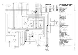
- 1. 66 Group 23 EDC III Electrical system Cable colors BL = Blue P = Pink LBL = Lightblue R = Red BN = Brown SB = Black LBN = Lightbrown VO = Violet GN = Green W = White GR = Gray Y = Yellow OR = Orange TAD1240–42GE, TAD124142VE (24 V system voltage, 2-pin) 1. RPM potentiometer 2. 1500/1800 contact 3. Starter contact 4. Idle contact 5. Stop contact 6. Diagnostics 7. Low oil pressure alarm 8. High coolant temperature alarm 9. Indicator, engine running 10. Overspeed alarm 11. Voltage after key 12. Battery, negative 13. Battery, positive 14. Nyckelbrytare 15. J1587 (bus) 16. J1939 CAN (bus) 17. Battery, negative 18. Battery, positive 19. Voltage after key 20. Connector 21. Programming connector 22. Diode 23. Monitor, water in fuel 24. Relay socket 25. Main relay 26. Monitor, fuel pressure 27. Monitor, coolant level 28. Stop 29. Programming plug 30. Connector 2 (red) 31. Connector 1 (black) 32. Control unit, EDC III (ECU) 33. Unit injector 34. Coolant temperature sensor 35. Sensor, charge air temperature/ pressure 36. Preheat function (NOT available for Genset application) 37. Camshaft (RPM) sensor 38. Flywheel (RPM) sensor 39. Generator 40. Starter motor 41. Sensor, oil temperature/pressure 42. Battery (24 V)
- 2. 67 Group 23 EDC III Electrical system Cable colors BL = Blue P = Pink LBL = Lightblue R = Red BN = Brown SB = Black LBN = Lightbrown VO = Violet GN = Green W = White GR = Gray Y = Yellow OR = Orange TWD1240VE (24 V system voltage, 2-pin) 1. RPM potentiometer 2. Droop contact 3. Starter contact 4. Idle contact 5. Preheating contact 6. Stop contact 7. Diagnostics 8. Low oil pressure alarm 9. High coolant temperature alarm 10. Low coolant level alarm 11. Preheating indicator 12. Voltage after key 13. Battery, negative 14. System to (key) 15. Battery, positive 16. J1587 (bus) 17. J1939 CAN (bus) 18. Battery, negative 19. Battery, positive 20. Voltage after key 21. Connector 22. Programming connector 23. Diode 24. Stop button 25. Monitor, water in fuel 26. Relay, socket 27. Relay 28. Programming plug 29. Monitor, fuel pressure 30. Monitor, coolant level 31. Connector 2 (red) 32. Connector 1 (black) 33. Control unit EDCIII (ECU) 34. Unit injectors (Cyl. 1–6) 35. Coolant temperature sensor 36. Sensor, Charge air temperature/ pressure 37. Preheating 38. Relay, preheating 39. Camshaft (RPM) sensor 40. Flywheel (RPM) sensor 41. Generator 42. Starter motor 43. Sensor, oil temperature/ pressure 44. Battery (24 V)
- 3. 68 Group 23 EDC III Electrical system Cable colors BL = Blue P = Pink LBL = Lightblue R = Red BN = Brown SB = Black LBN = Lightbrown VO = Violet GN = Green W = White GR = Gray Y = Yellow OR = Orange Wiring diagram, Control Interface Unit (CIU) 1. Key breaker operating power (15+) 2. RPM potentiometer 3. Tachometer code 14 4. Oil pressure, instrument 5. Oil temperature, instrument 6. Coolant temperature, instrument 7. Instrument illumination 8. Idle contact, two-position (Genset) 9. 1500/1800 contact, two-position (Genset) 10. Starter contact, non-locking 11. Stop contact, non-locking 12. Diagnosis contact, non-locking 13. Alarm, low oil pressure 14. Alarm, high oil temperature 15. Alarm, high coolant temperature 16. Alarm, coolant level 17. Fuel alarm 18. Diagnostic lamp 19. Overspeed indicator (Genset) 20. Operation indicator (Genset) 21. Preheating indicator (Versatile) 22. Preheating contact, non-locking (Versatile) 23. 8-pin Deutsch connection pin 24. Regulator (contact), two-position 25. Charge indicator 26. Termination 120 W 27. 8-pin Deutsch connection sleeve 28. Control Interface Unit (CIU)
- 4. 69 Group 23 EDC III Electrical system Cable colors BL = Blue P = Pink LBL = Lightblue R = Red BN = Brown SB = Black LBN = Lightbrown VO = Violet GN = Green W = White GR = Gray Y = Yellow OR = Orange Wiring diagram, Control Interface Unit (CIU) – Power pack 1. Activating operating power, contact (15+) 2. RPM potentiometer 3. Tachometer code 14 4. Oil pressure, instrument 5. Coolant temperature, instrument 6. Instrument illumination 7. Starter contact, non-locking 8. Stop contact, non-locking 9. Diagnosis contact, non-locking 10. Charge indicator 11. Alarm, high oil temperature 12. Alarm, high coolant temperature 13. Alarm, coolant level 14. Fuel alarm 15. Diagonotic lamp 16. Preheating indicator 17. 8-pin Deutsch connection pin 18. 8-pin Deutsch connection sleeve 19. Horn total alarm 20. Preheating contact, non-locking function (option) 21. 42-pin connector 22. Termination 120 W 23. Extra outlet for 24 V and stop 24. Control Interface Unit (CIU)
- 5. 70 Group 23 EDC III Index Index A About the Service Manual ...................................... 5 C Certifiedengines .................................................... 5 Check/fault detection of components .................... 49 Component description, sensors and monitors ...... 14 Componentdiagramandlocation .......................... 18 Control Interface Unit (CIU) ................................... 16 Controlmodule(EMS) ........................................... 16 Controlmodule(EMS),replacement ...................... 23 D Designandoperation ............................................ 12 Diagnostic function affects the engine .................. 27 Diagnostic function ............................................... 27 E Electrical system .................................................. 62 Electrical system, overview .................................. 63 Electronic fault detection....................................... 46 Erasing error codes ............................................... 28 F Fault codes EDC III .............................................. 29 Fault detection of cables and connectors .............. 47 Fault detection ...................................................... 26 Functionality check of lines and connectors.......... 46 Functionality check ............................................... 25 G General .................................................................. 8 Generalinformation ................................................ 5 General ................................................................. 46 Generator .............................................................. 17 I Important about the electrical system ................... 62 Introduction ............................................................ 2 L Limit values .......................................................... 19 Limit values, control unit (ECU) TAD1240-42GE ..................................................... 19 Limit values, control unit (ECU) TWD1240VE ......................................................... 20 Limp-homevalues ................................................. 21 Location of engine plates ....................................... 8 Lock nuts ................................................................ 7 O Our common responsibility..................................... 6 P PC diagnostics program ........................................ 25 R Reading out error codes ........................................ 27 Repairinstructions ................................................. 6 Repairinstructions ................................................ 22 S Safety information .................................................. 2 Sealants ................................................................ 7 Spareparts ............................................................ 5 Special tools .......................................................... 9 Splicing of electrical cable for cable glove............. 48 Start with booster batteries ................................... 24 Startermotor ......................................................... 17 Strength classes .................................................... 7 Symptoms and possible causes ........................... 26 System description EDC III................................... 12 T Technical data ...................................................... 10 The role of diagnostic function .............................. 27 Tighteningtorques ................................................. 6 Torque-angletightening ........................................... 7 U Unit injectors ......................................................... 17 W When working with EDC III.................................... 22 Wiring diagram TAD1240-42GE/VE ..................... 66 Wiring diagram TWD1240VE ................................ 67 Wiring diagram, Control Interface Unit (CIU) - Power pack ........................................................... 69 Wiring diagram, Control Interface Unit (CIU) .......... 68