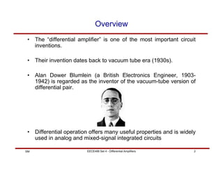
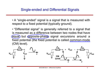
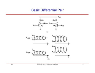
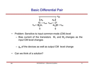
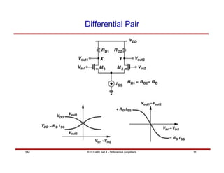
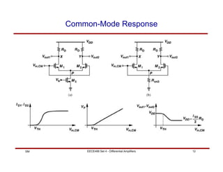
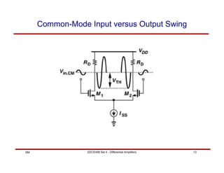
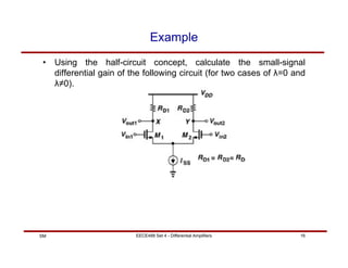
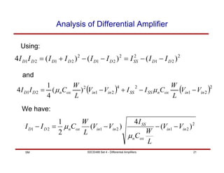
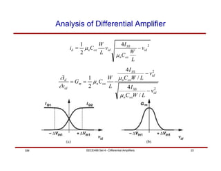
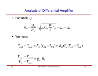
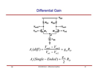
This document discusses differential amplifiers, which measure the difference between two input signals and offer advantages like noise immunity. It describes the basic differential pair circuit and how loading it with resistors can improve linearity and differential gain. The document also covers analyzing differential amplifiers, including their differential and common-mode gains, as well as more advanced topics like using MOS loads and the Gilbert cell configuration.

![EECE488 Set 4 - Differential Amplifiers 35
SM
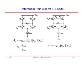
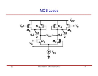
MOS Loads
Av ≈ gm1[(gm3ro3ro1 ) || (gm5ro5ro7 )]](https://image.slidesharecdn.com/5-220216171428/85/5-differential-amplifier-35-320.jpg)