ZX75US-5
Sample Parts &Service Manual — Technical Preview
This is a sample preview — full manual available at reliable-store.com
2.
117W-1-1
SECTION 1
GENERAL IMFORMATION
—CONTENTS—
Group1 Precautions for Disassembly
and Assembly
Precautions for Disassembly and
Assembly.............................................. W1-1-1
Group 2 Tightening
Tightening Torque Specification.............. W1-2-1
Torque Chart .......................................... W1-2-2
Piping Joint ............................................ W1-2-5
3.
GENERAL INFORMATION /Precautions for Disassembly and Assembly
W1-1-1
PRECAUTIONS FOR DISASSEMBLY AND
ASSEMBLY
Preparations for Disassembly
• Clean the Machine
Thoroughly wash the machine before bringing it into
the shop. Bringing a dirty machine into the shop may
cause machine components to be contaminated
during disassembling/assembling, resulting in
damage to machine components, as well as
decreased efficiency in service work.
• Inspect the Machine
Be sure to thoroughly understand all disassem-
bling/assembling procedures beforehand, to help
avoid incorrect disassembling of components as well
as personal injury.
Check and record the items listed below to prevent
problems from occurring in the future.
• The machine model, machine serial number, and
hour meter reading.
• Reason for disassembly (symptoms, failed parts,
and causes).
• Clogging of filters and oil, water or air leaks, if any.
• Capacities and condition of lubricants.
• Loose or damaged parts.
• Prepare and Clean Tools and Disassembly Area
Prepare the necessary tools to be used and the area
for disassembling work.
Precautions for Disassembly and Assembly
• Precautions for Disassembly
• To prevent dirt from entering the hydraulic system,
cap or plug the removed pipes.
• Before disassembling, clean the exterior of the
components and place them on a clean work
bench.
• Before disassembling, drain gear oil from the
reduction gear.
• Be sure to provide appropriate containers for
fluids.
• Use matching marks for easier reassembling.
• Be sure to use the specified tools, when
instructed.
• If a part or component cannot be removed after
removing its securing nuts and bolts, do not
attempt to remove forcibly. Find the cause(s), then
take the appropriate measures.
• Orderly arrange disassembled parts. Mark and
tag them as necessary.
• Store common parts, such as bolts and nuts with
reference to where they are to be used and in a
manner that will prevent loss.
• Inspect the contact or sliding surfaces of
disassembled parts for abnormal wear, sticking,
or other damage.
• Measure and record the degree of wear and
clearances.
• Precautions for Assembly
• Be sure to clean all parts and inspect them for any
damage. If any damage is found, repair or replace
it.
• Dirt or debris on the contact or sliding surfaces
may shorten the service life of the machine. Take
care not to contaminate any contact or sliding
surfaces.
• Be sure to replace O-rings, backup rings, and oil
seals with new ones once they are disassembled.
Apply a film of grease before installing.
• Be sure that liquid-gasket-applied surfaces are
clean and dry.
• If an anti-corrosive agent has been used on a new
part, be sure to thoroughly clean the part.
• Utilize matching marks when assembling.
• Be sure to use the designated tools to assemble
bearings, bushings and oil seals.
• Keep a record of the number of tools used for
disassembly/assembly. After assembling is
complete, count the tools, so as to make sure that
no tools are missing.
4.
GENERAL INFORMATION /Precautions for Disassembly and Assembly
W1-1-2
Bleeding Air from Hydraulic System
When hydraulic oil is drained, the suction filter or the
suction lines are replaced, or the removal and install
ation of the pump, swing motor, travel motor or
cylinder is done, bleed air from the hydraulic system
in the following procedures:
• Bleeding Air from Hydraulic Pump
IMPORTANT: If the engine is started with air
trapped in the hydraulic pump
housing, damage to the pump may
result. Be sure to bleed air before
starting the engine.
• Remove the air bleeding plug from the top of the
pump and fill the pump housing with hydraulic oil.
• After the pump housing is filled with hydraulic oil,
temporarily tighten the plug. Then, start the
engine and run at slow idle speed.
• Slightly loosen the plug to bleed air from the pump
housing until hydraulic oil oozes out.
• After bleeding all the air, securely tighten the plug.
• Bleeding Air from Travel Motor / Swing Motor
• With the drain plug / hose on travel motor / swing
motor removed, fill the motor case with hydraulic
oil.
• Bleeding Air from Hydraulic Circuit
• After refilling hydraulic oil, start the engine. While
operating each cylinder, swing motor and travel
motor evenly, operate the machine under light
loads for 10 to 15 minutes. Slowly start each
operation (never fully stroke the cylinders during
initial operation stage). As the pilot oil circuit has
an air bleed device, air trapped in the pilot oil
circuit will be bled while performing the above
operation for approx. 5 minutes.
• Reposition the front attachment to check hydraulic
oil level.
• Stop the engine. Recheck hydraulic oil level.
Replenish oil as necessary.
M104-07-021
5.
GENERAL INFORMATION /Precautions for Disassembly and Assembly
W1-1-3
Floating Seal Precautions
1. In general, always replace the floating seal with a
new one.
If the floating seal is to be reused, follow these
procedures:
(1) Keep seal rings together as a matched set with
seal ring faces together. Insert a piece of
cardboard to protect surfaces.
(2) Check seal ring face (A) for scuffing, scoring,
corrosion, deformation or uneven wear.
(3) Check O-ring (B) for tears, breaks, deformation
or hardening.
2. If incorrectly assembled, oil leakage or damage
will occur. Be sure to do the following, to prevent
trouble.
(1) Clean the floating seal and seal mounting
bores with cleaning solvent.
Use a wire brush to remove mud, rust or dirt.
After cleaning, thoroughly dry parts with
compressed air.
(2) Clean the floating seal and seal mounting
bores, as dust on them tends to enter the
floating seal when installing it.
(3) Check that the O-ring is not twisted, and that it
is installed correctly on the seal ring.
(4) After installing the floating seal, check that seal
ring surface (A) is parallel with mating face (C)
by measuring the distances (A) and (C) at point
(a) and (b), as illustrated. If these distances
differ, correct the O-ring seating.
W105-03-05-019
W105-03-05-020
W110-03-05-004
A
B
Incorrect
Correct
aҐb
b b
a
a
a=b
A
B
Correct Incorrect
C
GENERAL INFORMATION /Tightening Torque
W1-2-2
TORQUE CHART
CAUTION: Use tools appropriate for the
work to be done. Makeshift tools and
procedures can create safety hazards. For
loosening and tightening nuts and bolts, use
the correct tools. Avoid bodily injury caused
by slipping wrenches.
Bolt Types
Tighten nuts or bolts correctly to torque specifications.
Four kinds of bolts, hexagon bolts T, H, M and socket
bolts, each made of different material, are used.
Make sure to employ the correct bolts and tighten
them to specification when assembling the machine
or components.
SA-040
W162-01-01-001
Specified Tightening Torque Chart
T Bolt, Socket Bolt H Bolt M Bolt
Bolt
Dia.
Wrench
Size
Hexagon
Wrench
Size N⋅m (kgf⋅m) (lbf⋅ft) N⋅m (kgf⋅m) (lbf⋅ft) N⋅m (kgf⋅m) (lbf⋅ft)
M 8 13 6 29.5 (3) (22) 19.5 (2) (14.5) 9.8 (1) (7.2)
M 10 17 8 64 (6.5) (47) 49 (5) (36) 19.5 (2)) (14.5)
M 12 19 10 108 (11) (80) 88 (9) (65) 34 (3.5) (25.5)
M 14 22 12 175 (18) (130) 137 (14) (101) 54 (5.5) (40)
M 16 24 14 265 (27) (195) 205 (21) (152) 78 (8) (58)
M 18 27 14 390 (40) (290) 295 (30) (220) 118 (12) (87)
M 20 30 17 540 (55) (400) 390 (40) (290) 167 (17) (123)
M 22 32 17 740 (75) (540) 540 (55) (400) 215 (22) (159)
M 24 36 19 930 (95) (690) 690 (70) (505) 275 (28) (205)
M 27 41 19 1370 (140) (1010) 1030 (105) (760) 390 (40) (290)
M 30 46 22 1910 (195) (1410) 1420 (145) (1050) 540 (55) (400)
M 33 50 24 2550 (260) (1880) 1910 (195) (1410) 740 (75) (540)
M 36 55 27 3140 (320) (2310) 2400 (245) (1770) 930 (95) (690)
Socket Bolt
Hexagon M Bolt
Hexagon H Bolt
Hexagon T Bolt
9.
GENERAL INFORMATION /Tightening Torque
W1-2-5
PIPING JOINT
Pipe Thread Connection/Union Joint Tightening
Torque Specifications
Union Joint
Metal sealing faces (4) and (5) of adaptor (1) and
hose (2) fit together to seal pressure oil. Union joints
are used to join small-diameter lines.
IMPORTANT: (1) Do not over-tighten union nut (3).
Excessive force will be applied to
metal sealing surfaces (4) and (5),
possibly cracking adaptor (1). Be
sure to tighten union nut (3) to
specifications.
(2) Scratches or other damage to
sealing surfaces (4) or (5) will
cause oil leakage at the joint.
Take care not to damage them
when connecting /disconnecting.
O-Ring Seal Joint
O-ring (6) seats against the end face of adaptor (7) to
seal pressure oil.
IMPORTANT: (1) Be sure to replace O-ring (6) with
a new one when reconnecting.
(2) Before tightening union nut (9),
confirm that O-ring (6) is seated
correctly in O-ring groove (8).
Tightening union nut (9) with O-
ring (6) displaced will damage O-
ring (6), resulting in oil leakage.
(3) Take care not to damage O-ring
groove (8) or sealing face (10).
Damage to O-ring (6) will cause
oil leakage.
(4) If union nut (9) is found to be
loose, causing oil leakage, do not
tighten it to stop the leak. Instead,
replace O-ring (6) with a new one,
then tighten union nut (9) after
confirming that O-ring (6) is
securely seated in place.
M202-07-051
W105-01-01-017
Tightening Torque
Wrench Size
mm N⋅m (kgf⋅m) (Ibf⋅ft)
19
22
27
32
36
41
50
29
39
93
137
175
205
255
(3.0)
(4.0)
(9.5)
(14)
(18)
(21)
(26)
(22)
(29)
(69)
(101)
(130)
(152)
(188)
M104-07-033
Tightening Torque
Wrench Size
mm N⋅m (kgf⋅m) (Ibf⋅ft)
27
32
36
41, 46
93
137
175
205
(9.5)
(14)
(18)
(21)
(69)
(101)
(130)
(152)
Female Union Joint
Male Union Joint
30° or 37°
30° or 37°
7
Joint Body
6 9
1
8
4
10
3 5 2
10.
GENERAL INFORMATION /Tightening Torque
W1-2-7
Connecting Hose
CAUTION:
(1) When replacing hoses, be sure to use
only genuine Hitachi service parts. Using
hoses other than genuine Hitachi hoses
may cause oil leakage, hose rupture or
separation of fitting, possibly resulting in
a fire on the machine.
(2) Do not install hoses kinked. Application
of high oil pressure, vibration, or an
impact to a kinked hose may result in oil
leakage, hose rupture or separation of
fitting. Utilize print marks on hoses when
installing hoses to prevent hose from
being installed kinked.
(3) If hoses rub against each other, wear to
the hoses will result, leading to hose
rupture. Take necessary measures to
protect hoses from rubbing against each
other.
Take care that hoses do not come into
contact with moving parts or sharp
objects.
W105-01-01-011
W105-01-01-012
W105-01-01-013
W105-01-01-014
RIGHT
WRONG
Rubbing Against
Each Other
RIGHT
WRONG
RIGHT
WRONG
Rubbing
Clamp Clamp
WRONG
Rubbing
Clamp
RIGHT
11.
117W-2-1
SECTION 2
UPPERSTRUCTURE
—CONTENTS—
Group 1Cab
Windowpane Dimensions ......................... W2-1-1
Group 2 Pump Device
Remove and Install
Pump Device .......................................... W2-2-1
Pump Device Line Connection.................. W2-2-3
Disassemble Main Pump.......................... W2-2-4
Assemble Main Pump............................. W2-2-10
Maintenance Standards.......................... W2-2-13
Disassemble Regulator .......................... W2-2-14
Assemble Regulator ............................... W2-2-20
Disassemble and Assemble
4-Unit Pump ......................................... W2-2-27
Disassemble Fan Drive Pump ................ W2-2-28
Assemble Fan Drive Pump ..................... W2-2-32
Maintenance Standards.......................... W2-2-34
Disassemble Regulator .......................... W2-2-36
Assemble Regulator ............................... W2-2-40
Disassemble and Assemble Compressor
Drive Pump ⋅ Pilot Pump....................... W2-2-42
Disassemble and Assemble Transmission
Oil Cooling Pump.................................. W2-2-44
Group 3 Control Valve
Remove and Install
Control Valve .......................................... W2-3-1
Pilot Line Port Location ............................ W2-3-3
Main Hydraulic Line Port Location ............ W2-3-4
Disassemble and Assemble
Control Valve .......................................... W2-3-5
Group 4 Swing Device
Remove and Install Swing Device............. W2-4-1
Disassemble Swing Device....................... W2-4-2
Assemble Swing Device ........................... W2-4-6
Disassemble Swing Motor ...................... W2-4-12
Assemble Swing Motor ........................... W2-4-14
Maintenance Standard............................ W2-4-16
Disassemble and Assemble
Relief Block .......................................... W2-4-17
Group 5 Pilot Valve
Remove and Install Front/Swing
Pilot Valve............................................... W2-5-1
Remove and Install Travel and Bucket
Open/Close Pilot Valves ......................... W2-5-3
Pilot Valve Ports ....................................... W2-5-5
Disassemble and Assemble
Pilot Valve............................................... W2-5-6
Group 6 Pilot Shut-Off Valve
Remove and Install
Shut-Off Valve .......................................... W2-6-1
Disassemble Pilot Shut-Off Valve ............. W2-6-2
Assemble Pilot Shut-Off Valve .................. W2-6-4
12.
UPPERSTRUCTURE / PumpDevice
W2-2-1
REMOVE AND INSTALL PUMP DEVICE
CAUTION: Escaping fluid under pressure
can penetrate the skin and eyes, causing
serious injury. Avoid this hazard by relieving
pressure before disconnecting hydraulic or
other lines.
Hydraulic oil may be hot just after operation.
Hot hydraulic oil may spout, possibly causing
severe burns. Be sure to wait for oil to cool
before starting work.
Do not quickly loosen the cap on the hydrau-
lic oil tank. The cap may fly off due to internal
pressure. Always turn the cap slowly to re-
lease any remaining pressure before remov-
ing it.
Preparation:
1. Stop the engine. Move all control levers to release
the pressure remaining in the system. Slowly turn
the cap on the hydraulic oil tank approximately 30
degrees counter-clockwise to release any
remaining pressure.
2. Close all hydraulic line stop valves.
13.
UPPERSTRUCTURE / PumpDevice
W2-2-2
Removal
1. Disconnect all wire harness ends and hydraulic
line ends from the pump.
CAUTION: Pump Device Weight:
298 kg (657 Ib)
Approximate Quadruple Pump Weight: 100 kg
(220 Ib)
2. Remove the pump mounting bolts to remove the
pumps.
: 36 mm
: 690 N⋅m (70 kgf⋅m, 507 lbf⋅ft)
: 30 mm
: 390 N⋅m (40 kgf⋅m, 290 lbf⋅ft)
Installation
NOTE: Refar to the Removal section for wrench
size and tightening torque.
1. Install the pumps using the mounting bolts.
2. Connect all wire harness ends and hydraulic line
ends to the pump.
3. Bleed the air from the pump. (Refer to W1-1-2)
IMPORTANT: Prevent pump seizure from
occurring. Be sure to perform
running-in operation after installing
the pumps.
Pump Running-In Operation Procedure:
1. Run the engine at slow idle for 20 minutes.
Check for oil leaks during the engine idling
operation.
2. Increase the engine speed to the maximum
speed. Slowly operate the boom from stroke
end to stroke end repeatedly for 20 minutes.
T117-02-01-001
M117-07-118
Mounting Bolt
Air Bleed Position Air Bleed Position
UPPERSTRUCTURE / PumpDevice
W2-2-7
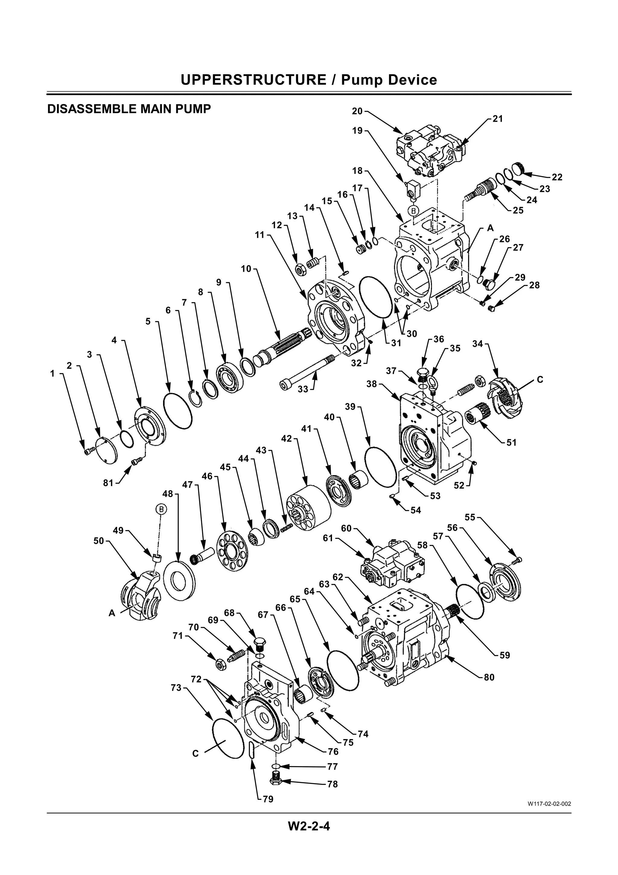
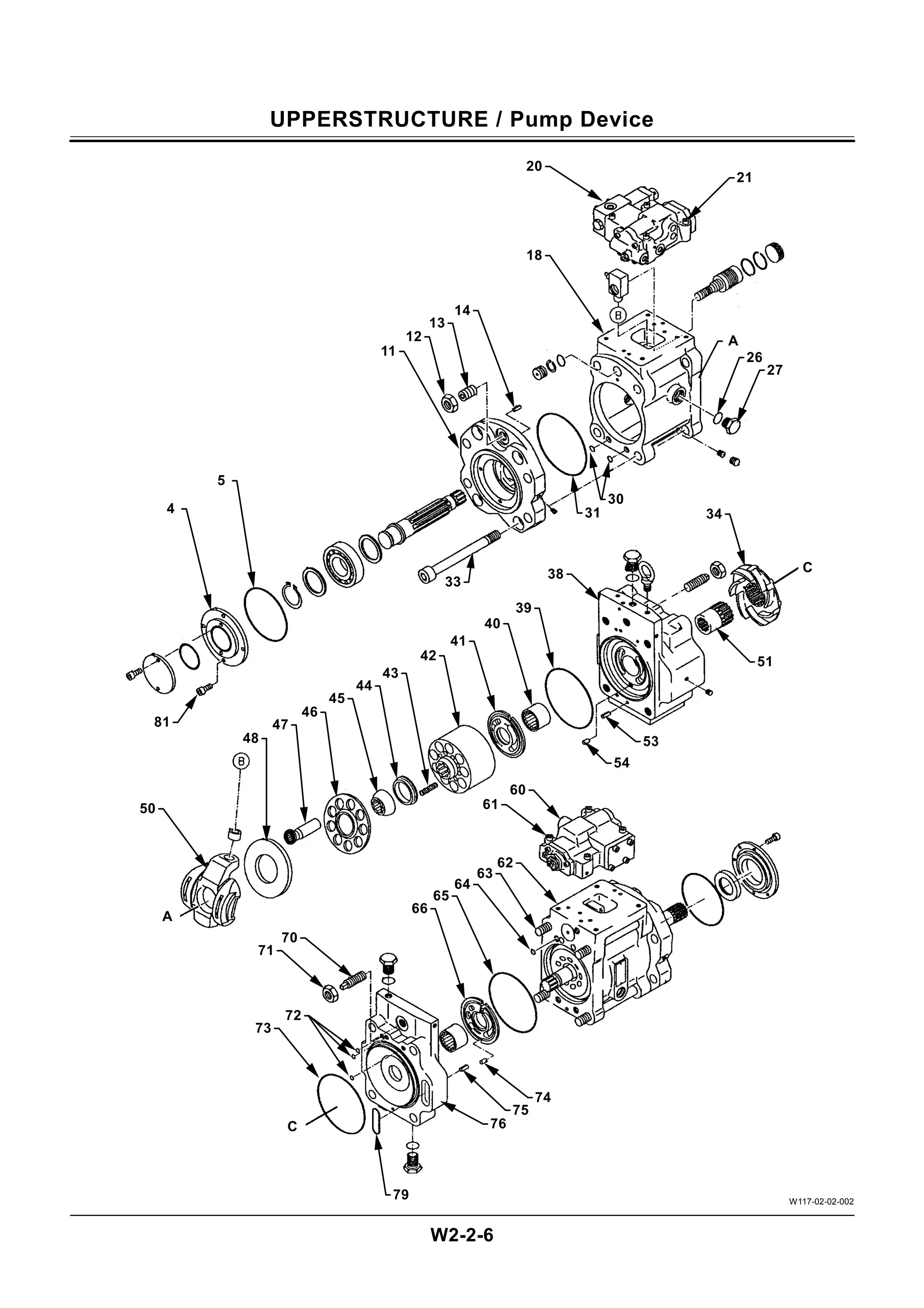
Disassemble Main Pump
IMPORTANT: Do not attempt to remove nut (12),
adjusting screw (13), nut (71), and
adjusting screw (70). Leave them as
installed. The set flow rate may be
altered.
1. Remove plugs (27) (2 used) and O-rings (26) (2
used) to drain hydraulic oil from the pump.
: 36 mm
2. Remove socket bolts (21) (4 used) and (61) (4
used) to remove regulators (20) and (60),
respectively.
: 6 mm
3. Turn the pump over (on the regulator mounting
side). Remove socket bolts (33) (4 used) and (63)
(4 used).
: 17 mm
4. Separate housing (18), valve cover (38), cover
(76), and housing (62) assemblies. Be sure to
remove O-rings (39), (65), (64), (72), (73), and
(79) and spring pins (53) and (75) when
separating these assemblies.
NOTE: Take care not to drop valve plates (41) and
(66) while separating these assemblies.
5. Remove booster (34), coupling (51), valve plate
(41) and pin (54) from valve cover (38).
NOTE: Do not remove needle bearing (40) unless
required.
6. Remove cylinder block (42), springs (43) (9 used),
spacer (44), spherical bushing (45), retainer (46),
and plungers (47) (9 used) from housing (18).
7. Remove socket bolts (81) (4 used) to remove
cover (4) and O-ring (5).
: 6 mm
8. Tap on cover (11) using a plastic hammer to
remove it. Remove O-rings (30) (2 used) and (31),
and spring pin (14) as well.
9. Remove swash plate (50) and shoe plate (48)
from housing (18).
GENERAL INFORMATION /Tightening Torque
W1-2-3
IMPORTANT: (1) Apply lubricant (i. e. white zinc B
dissolved into spindle oil) to nuts
and bolts to stabilize their friction
coefficients.
(2) Torque tolerance is ±
±
±
±10 %.
(3) Be sure to use bolts of correct
length. Bolts that are too long
cannot be tightened, as the bolt
tip comes into contact with the
bottom of the bolt hole. Bolts that
are too short cannot develop
sufficient tightening force.
(4) The torques given in the chart
are for general use only.
Do not use these torques if a
different torque is given for a
specific application.
(5) Make sure that the nut and bolt
threads are clean before
installing. Remove dirt or
corrosion, if any.
Bolt Tightening Order
When tightening two or more bolts, tighten them
alternately, as shown, to ensure even tightening.
W105-01-01-003
Tighten from center
and diagonally
Tighten diagonally
Equally tighten upper
and lower alternately
14
7
6
1
4
9
12
6
4
2
5
3
1
2,3
1,4
11
10
3
2
5
8
13
19.
GENERAL INFORMATION /Tightening Torque
W1-2-4
Service Recommendations for Split Flange
IMPORTANT: (1) Be sure to clean and inspect
sealing surfaces. Scratches /
roughness cause leaks and seal
wear. Unevenness causes seal
extrusion. If defects cannot be
removed, replace the component.
(2) Be sure to use only specified O-
rings. Inspect O-rings for any
damage. Take care not to file O-
ring surfaces. When installing an
O-ring into a groove, use grease
to hold it in place.
(3) Loosely assemble split flange
halves. Make sure that the split is
centrally located and
perpendicular to the port. Hand-
tighten the bolts to hold the parts
in place. Take care not to pinch
the O-ring.
(4) Tighten bolts alternately and
diagonally, as shown, to ensure
even tightening.
(5) Do not use air wrenches. Using
an air wrench often causes
tightening of one bolt fully before
tighten the others, resulting in
damage to O-rings or uneven
tightening of bolts.
Nut and Bolt Lockings
• Lock Plate
IMPORTANT: Do not reuse lock plates. Do not try
to bend the same point twice.
• Cotter Pin
IMPORTANT: Do not reuse cotter pins. Match the
holes in the bolt and nut while
tightening, not while loosening.
• Lock Wire
IMPORTANT: Apply wire to bolts in the bolt-
tightening direction, not in the bolt-
loosening direction.
W105-01-01-015
W105-01-01-016
W105-01-01-008
W105-01-01-009
W105-01-01-010
WRONG
WRONG
WRONG
RIGHT
RIGHT
Bend along edge sharply
Do not bend it round
Bend along edge sharply
RIGHT
Tighten
Loosen WRONG
WRONG
RIGHT
RIGHT
RIGHT
20.
GENERAL INFORMATION /Tightening Torque
W1-2-6
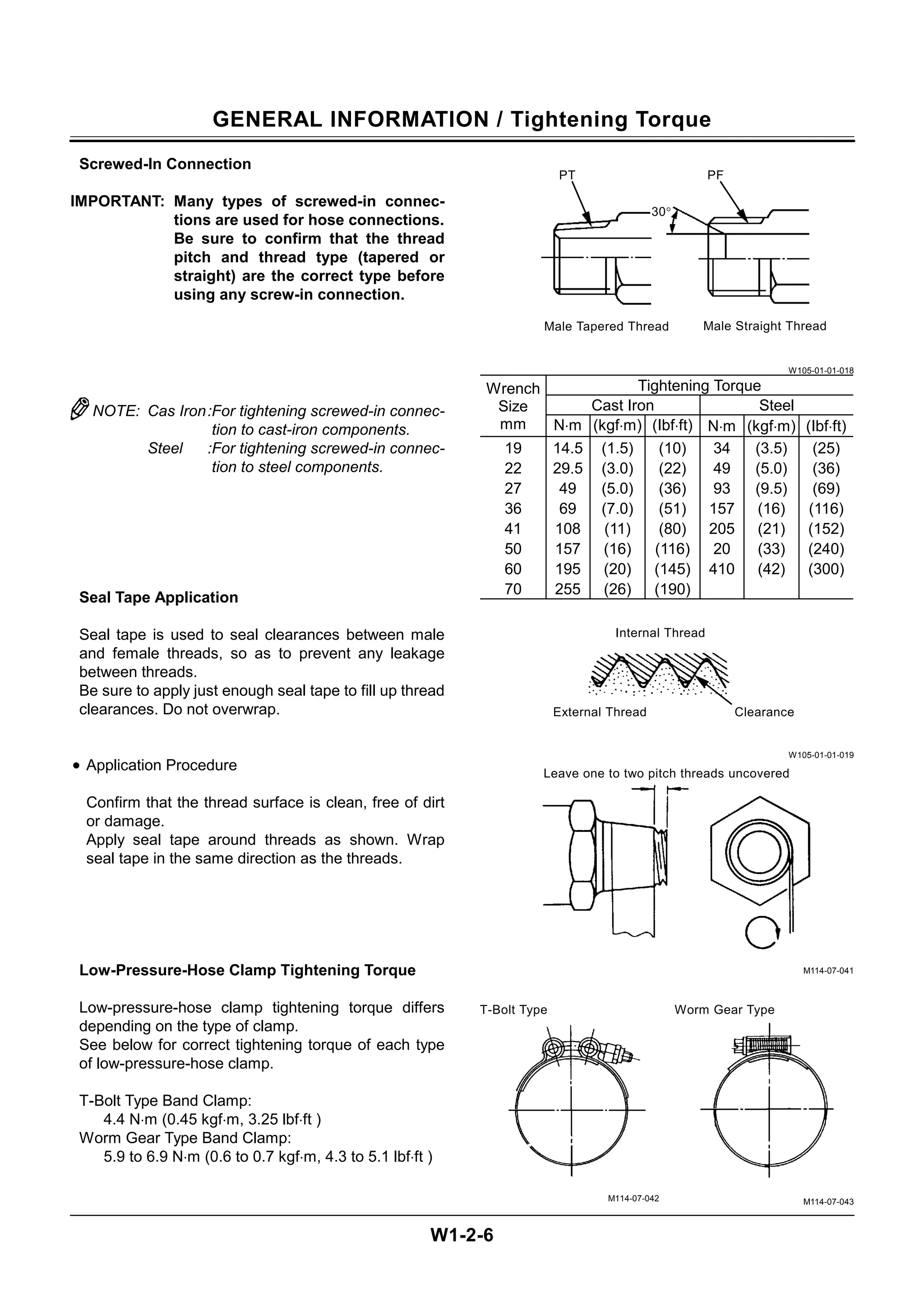
Screwed-In Connection
IMPORTANT: Many types of screwed-in connec-
tions are used for hose connections.
Be sure to confirm that the thread
pitch and thread type (tapered or
straight) are the correct type before
using any screw-in connection.
NOTE: Cas Iron:For tightening screwed-in connec-
tion to cast-iron components.
Steel :For tightening screwed-in connec-
tion to steel components.
Seal Tape Application
Seal tape is used to seal clearances between male
and female threads, so as to prevent any leakage
between threads.
Be sure to apply just enough seal tape to fill up thread
clearances. Do not overwrap.
• Application Procedure
Confirm that the thread surface is clean, free of dirt
or damage.
Apply seal tape around threads as shown. Wrap
seal tape in the same direction as the threads.
Low-Pressure-Hose Clamp Tightening Torque
Low-pressure-hose clamp tightening torque differs
depending on the type of clamp.
See below for correct tightening torque of each type
of low-pressure-hose clamp.
T-Bolt Type Band Clamp:
4.4 N⋅m (0.45 kgf⋅m, 3.25 lbf⋅ft )
Worm Gear Type Band Clamp:
5.9 to 6.9 N⋅m (0.6 to 0.7 kgf⋅m, 4.3 to 5.1 lbf⋅ft )
W105-01-01-018
Tightening Torque
Cast Iron Steel
Wrench
Size
mm N⋅m (kgf⋅m) (Ibf⋅ft) N⋅m (kgf⋅m) (Ibf⋅ft)
19
22
27
36
41
50
60
70
14.5
29.5
49
69
108
157
195
255
(1.5)
(3.0)
(5.0)
(7.0)
(11)
(16)
(20)
(26)
(10)
(22)
(36)
(51)
(80)
(116)
(145)
(190)
34
49
93
157
205
20
410
(3.5)
(5.0)
(9.5)
(16)
(21)
(33)
(42)
(25)
(36)
(69)
(116)
(152)
(240)
(300)
W105-01-01-019
M114-07-041
T-Bolt Type
M114-07-042
Worm Gear Type
M114-07-043
Male Straight Thread
Male Tapered Thread
Clearance
External Thread
Internal Thread
Leave one to two pitch threads uncovered
PT
30°
PF
117W-2-2
Group 7 SolenoidValve
Remove and Install
Solenoid Valve........................................ W2-7-1
Disassemble and Assemble
Fan Motor Solenoid Valve....................... W2-7-2
Disassemble and Assemble Horsepower
Reducing Solenoid Valve ........................ W2-7-3
Disassemble and Assemble
EHC Valve .............................................. W2-7-4
Disassemble and Assemble
Swing Stop Solenoid Valve ..................... W2-7-5
Disassemble and Assemble Travel Mode Shift
Solenoid Valve........................................ W2-7-6
Group 8 Fan Drive Motor
Remove and Install
Fan Drive Motor...................................... W2-8-1
Disassemble Fan Drive Motor .................. W2-8-4
Assemble Fan Drive Motor ....................... W2-8-6
Maintenance Standards............................ W2-8-8
Group 9 Compressor Drive Motor
Remove and Install
Compressor Drive Motor......................... W2-9-1
Disassemble and Assemble
Compressor Drive Motor......................... W2-9-4
Group 10 Air Conditioner
Work After Component
Replacement ........................................ W2-10-1
Add Compressor Oil ............................... W2-10-1
Charge Air Conditioner with
Refrigerant ........................................... W2-10-2
23.
UPPERSTRUCTURE / Cab
W2-1-1
WINDOWPANEDIMENSIONS
Material : JIS R 3211 or equivalent
NOTE: 1 mm=0.03937 in Unit:mm
W117-02-01-001
W117-02-01-003
W117-02-01-002
W117-02-01-004
2
3
4
5
7
6
1
1679+2.0
−0
1378±1.5
Laminated glass
Color : Transparent
Thickness : 10 mm
Chamfer all fringe Corners.
1
4-R91
Tempered glass
Color : Bronze
Thickness : 6 mm
Chamfer all fringe Corners.
2
4-R61
1369±1.5
917±1.0
1256±1.5
Tempered glass
Color : Bronze
Thickness : 5 mm
Chamfer all fringe
Corners.
3
4-R61
433±1.0
769±1.0
24.
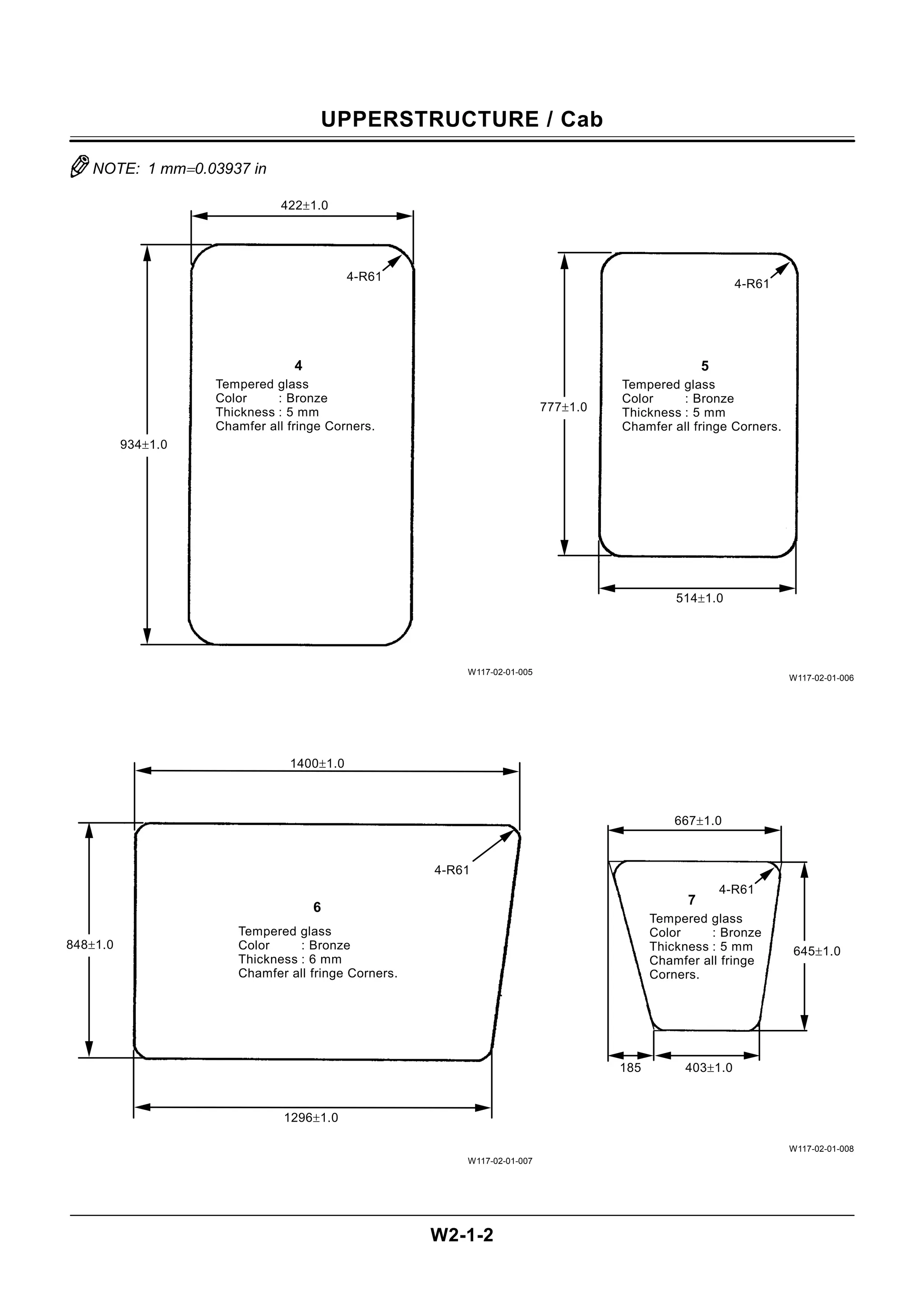
UPPERSTRUCTURE / Cab
W2-1-2
NOTE:1 mm=0.03937 in
W117-02-01-005
W117-02-01-007
W117-02-01-006
W117-02-01-008
Tempered glass
Color : Bronze
Thickness : 6 mm
Chamfer all fringe Corners.
6
4-R61
848±1.0
1296±1.0
1400±1.0
Tempered glass
Color : Bronze
Thickness : 5 mm
Chamfer all fringe
Corners.
7
4-R61
645±1.0
185 403±1.0
667±1.0
Tempered glass
Color : Bronze
Thickness : 5 mm
Chamfer all fringe Corners.
5
4-R61
514±1.0
777±1.0
Tempered glass
Color : Bronze
Thickness : 5 mm
Chamfer all fringe Corners.
4
4-R61
934±1.0
422±1.0
25.
UPPERSTRUCTURE / PumpDevice
W2-2-3
PUMP DEVICE LINE CONNECTION
T117-02-01-001
1 - Main Pump 3 (Transmission Side)
Main Pump 4 (Tip Side)
3 - Main Pump 1 (Transmission Side)
Main Pump 2 (Tip Side)
5 - Suction Line 6 - Delivery Line
2 - Main Pump 5 (Transmission Side)
Main Pump 6 (Tip Side)
4 - Quadruple Pump
T117-02-01-004
Psv - Pump Servo Assist Pressure (From the pilot pump) Pf - Horsepower Reducing Control Pressure
(Horsepower Reducing Solenoid Valve)
Pi - Flow Rate Control Pressure
(Switch Valves 1 and 2, Pressure Reducing Valve)
Pz -Horsepower Increasing Control Pressure
(EHC Valve)
6
6
5
1
6
2
3
5
4
5
Pi Pf
Psv Pz
Pi
Psv
Pz
Get the completemanual
Get the complete manual including full parts diagrams, torque specs &
troubleshooting. Download now from reliable-store.com
Download full official manual — reliable-store.com