4.5
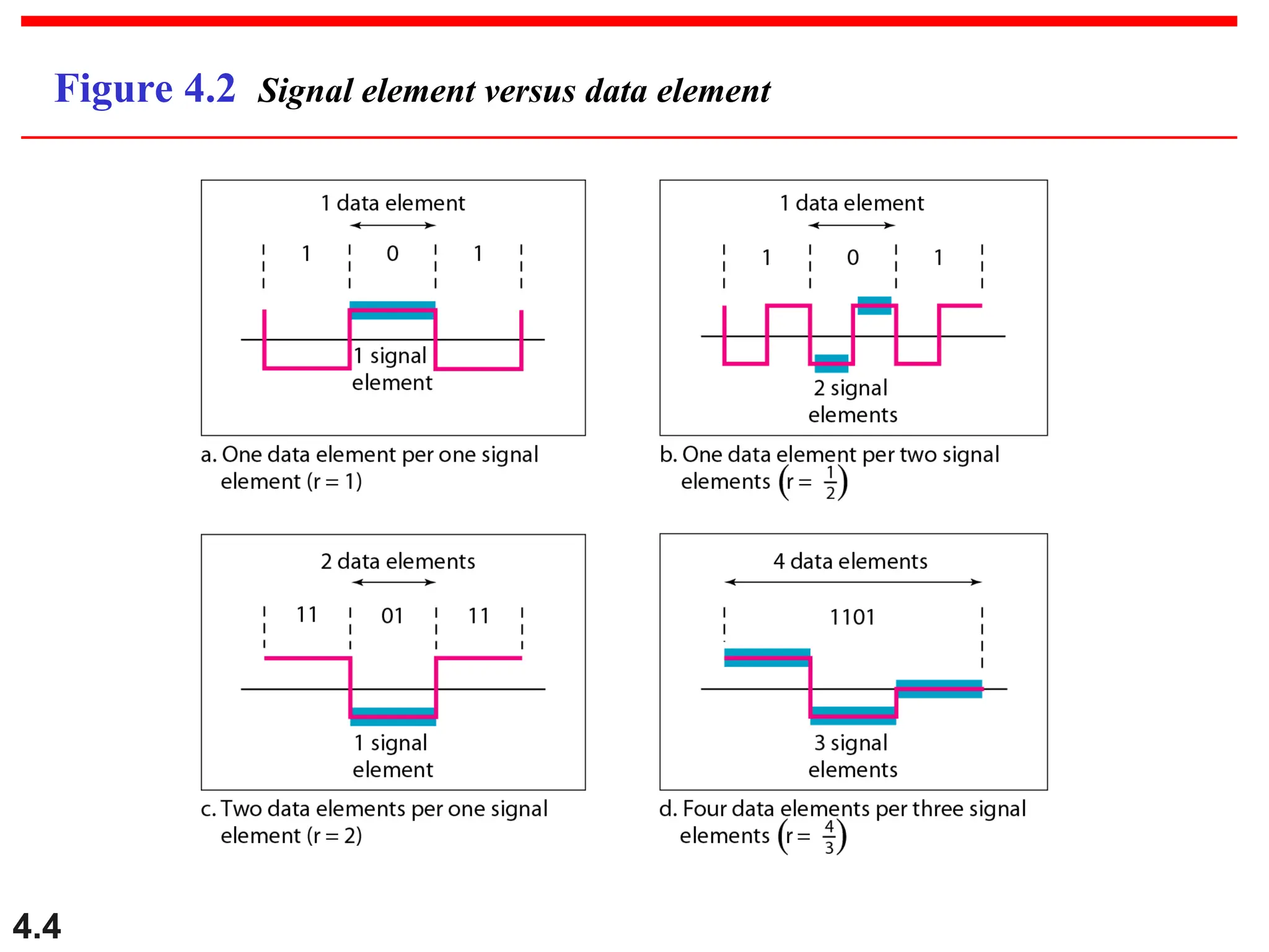
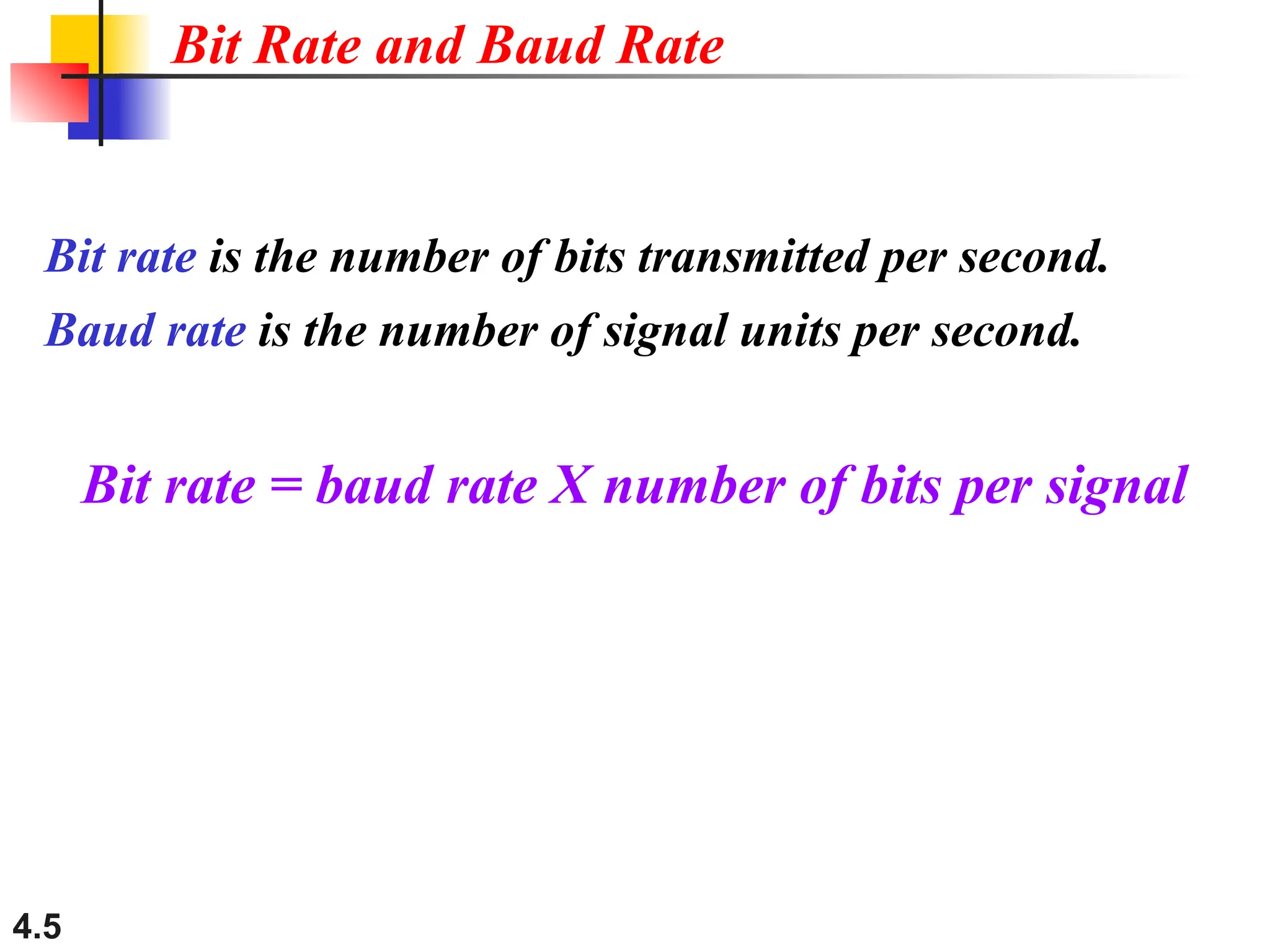
Bit rate isthe number of bits transmitted per second.
Baud rate is the number of signal units per second.
Bit rate = baud rate X number of bits per signal
Bit Rate and Baud Rate
6.
4.6
A signal iscarrying four bits in each signal element. If
1000 signal elements are sent per second, find the bit rate
and baud rate.
Solution:
Baud rate = No. of signal elements/sec
= 1000 baud/sec
Bit rate = Baud rate X No. of bits per signal elements
= 1000 X 4= 4000 bps
Example 1
7.
4.7
The bit rateof a signal is 3000. If each signal elements
carries 6 bits, what is the baud rate?
Solution:
Bit rate = Baud rate X No. of bits per signal elements
Baud rate = No. of bits per signal elements/bit rate
= 3000 /6 = 500 baud/sec
Example 1
4.9
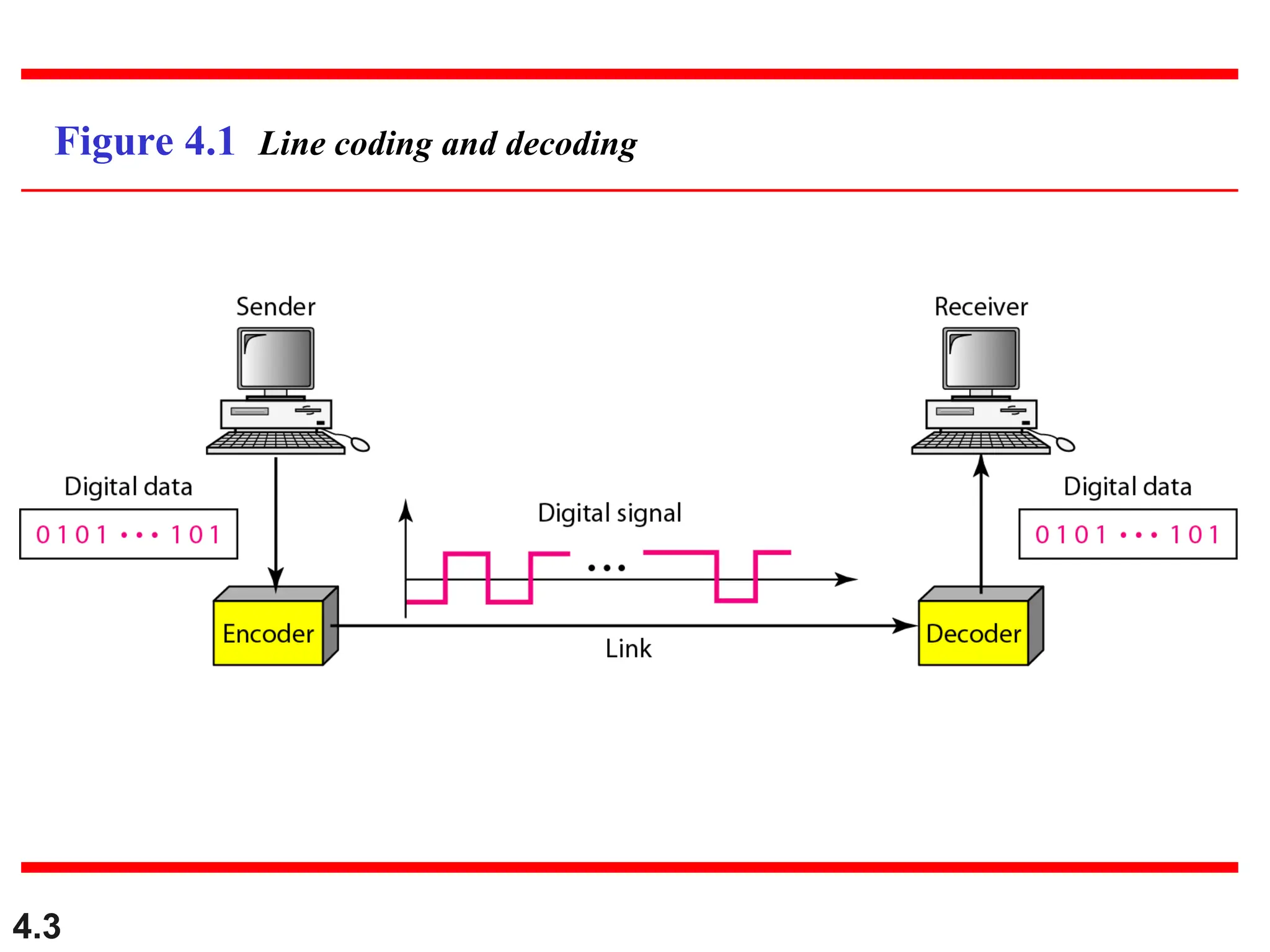
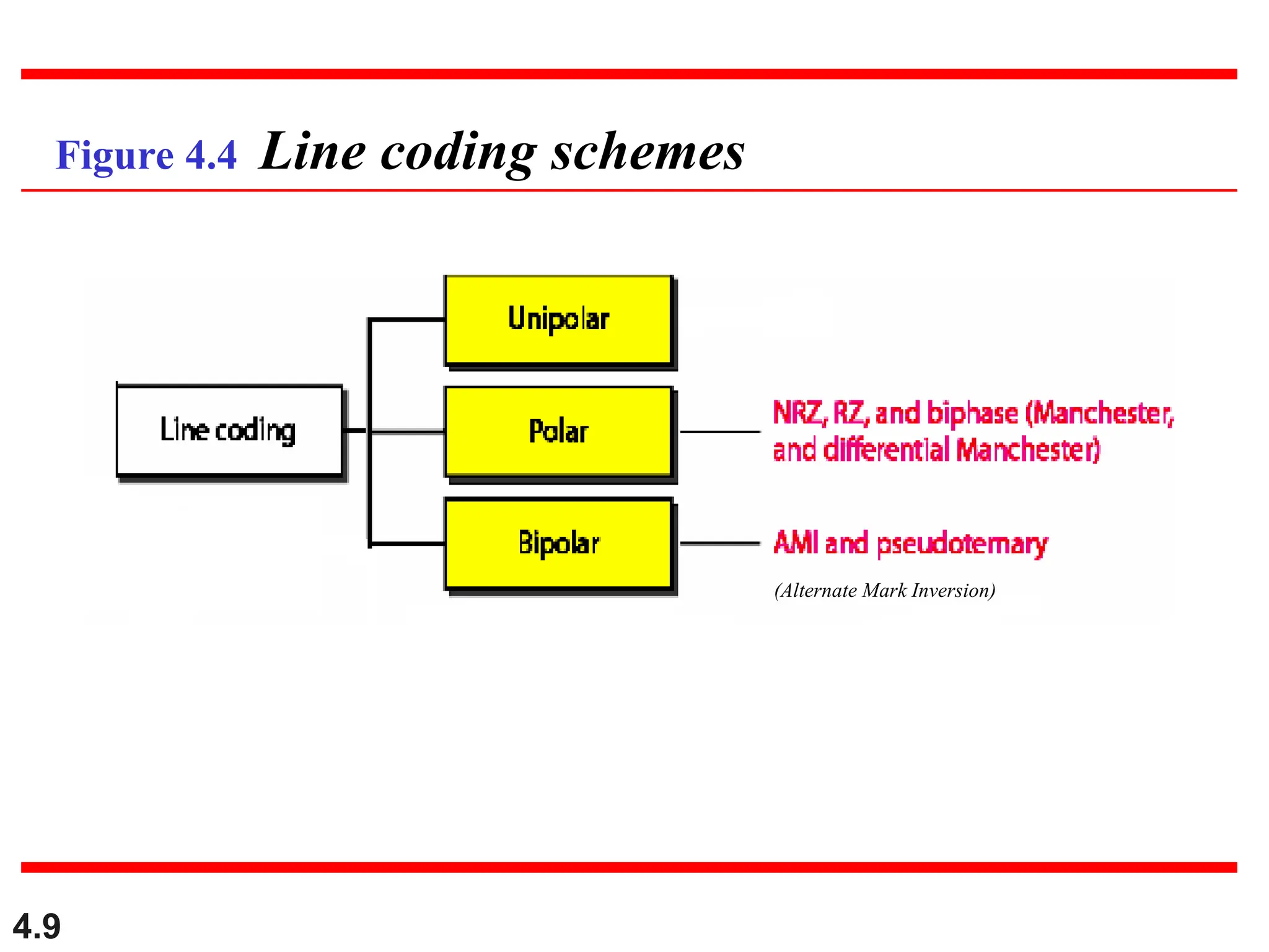
Figure 4.4 Linecoding schemes
(alternate mark inversion)
(Alternate Mark Inversion)
10.
4.10
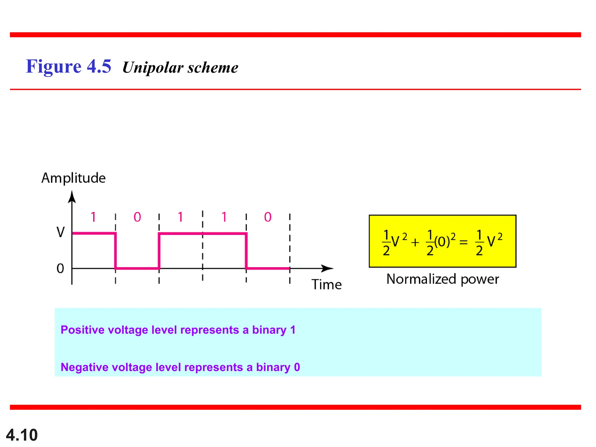
Figure 4.5 Unipolarscheme
Positive voltage level represents a binary 1
Negative voltage level represents a binary 0
11.
4.11
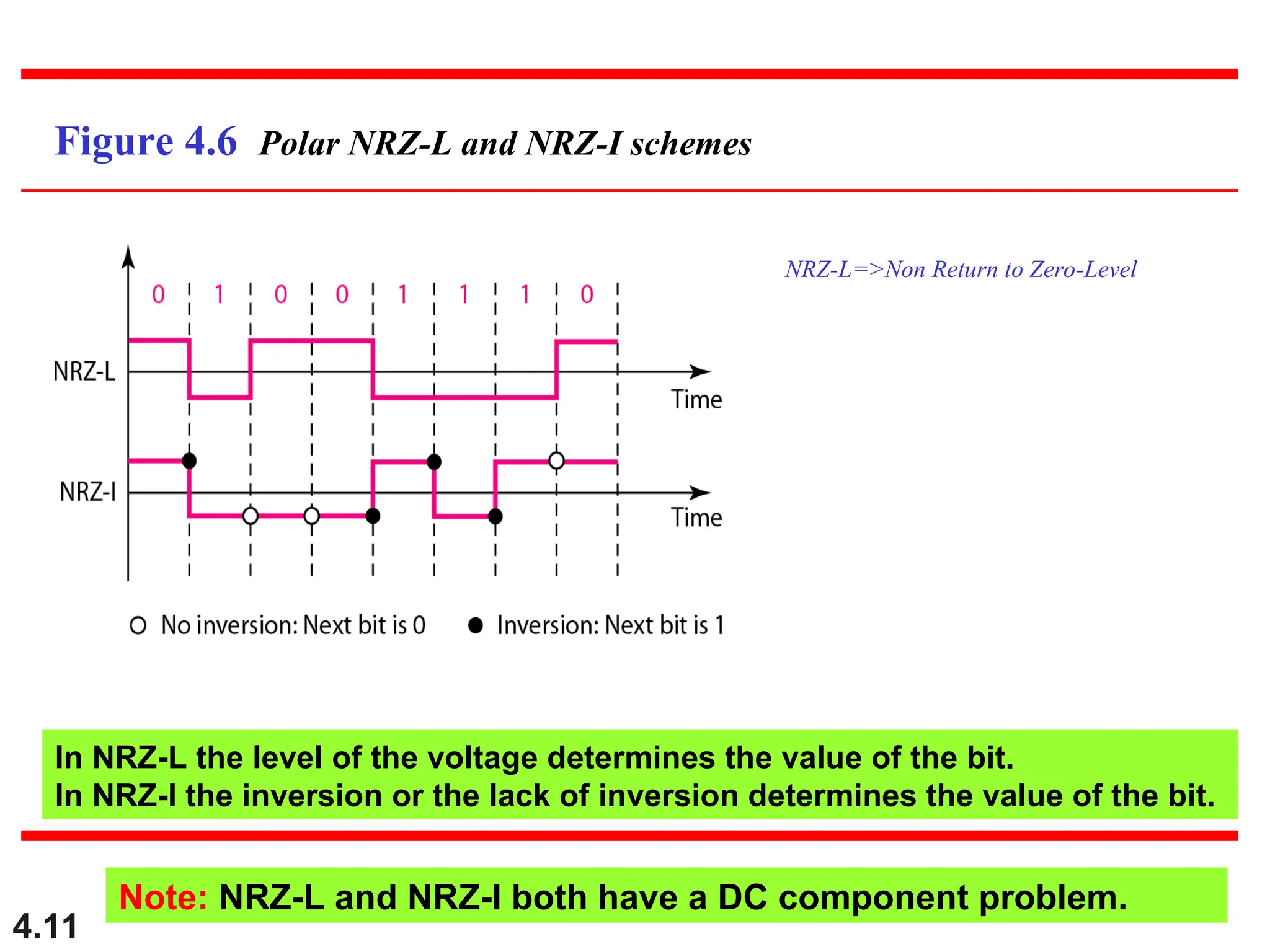
Figure 4.6 PolarNRZ-L and NRZ-I schemes
In NRZ-L the level of the voltage determines the value of the bit.
In NRZ-I the inversion or the lack of inversion determines the value of the bit.
Note: NRZ-L and NRZ-I both have a DC component problem.
NRZ-L=>Non Return to Zero-Level
4.13
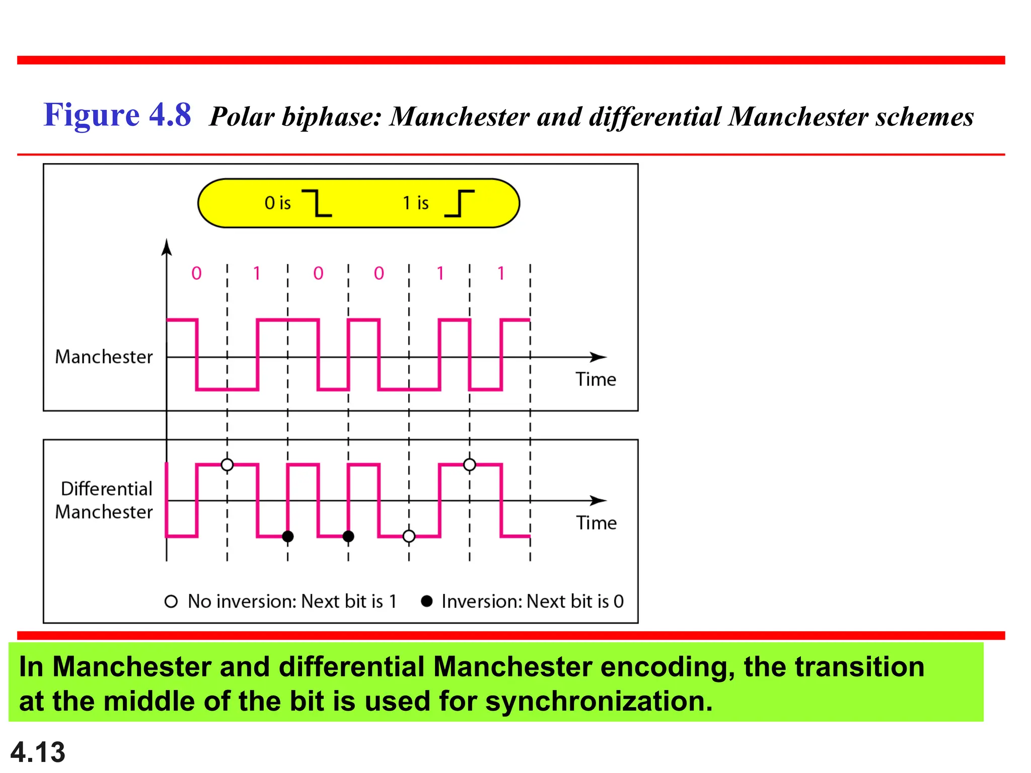
Figure 4.8 Polarbiphase: Manchester and differential Manchester schemes
In Manchester and differential Manchester encoding, the transition
at the middle of the bit is used for synchronization.
14.
4.14
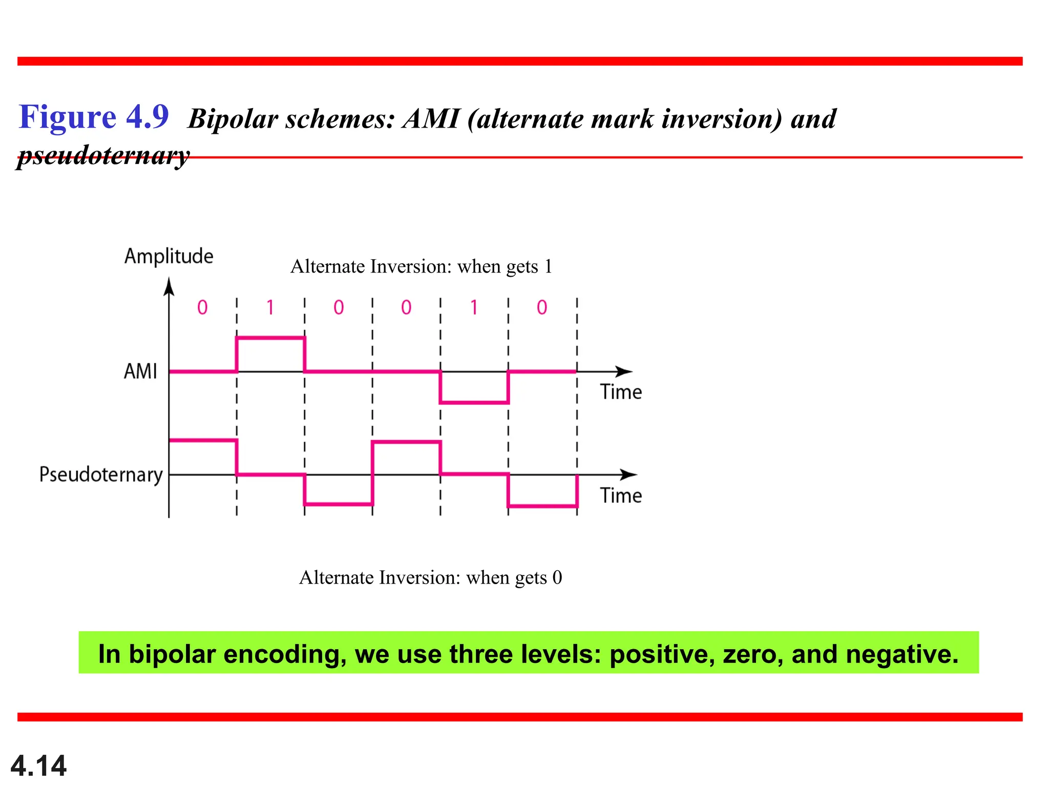
Figure 4.9 Bipolarschemes: AMI (alternate mark inversion) and
pseudoternary
Alternate Inversion: when gets 1
Alternate Inversion: when gets 0
In bipolar encoding, we use three levels: positive, zero, and negative.
4.20
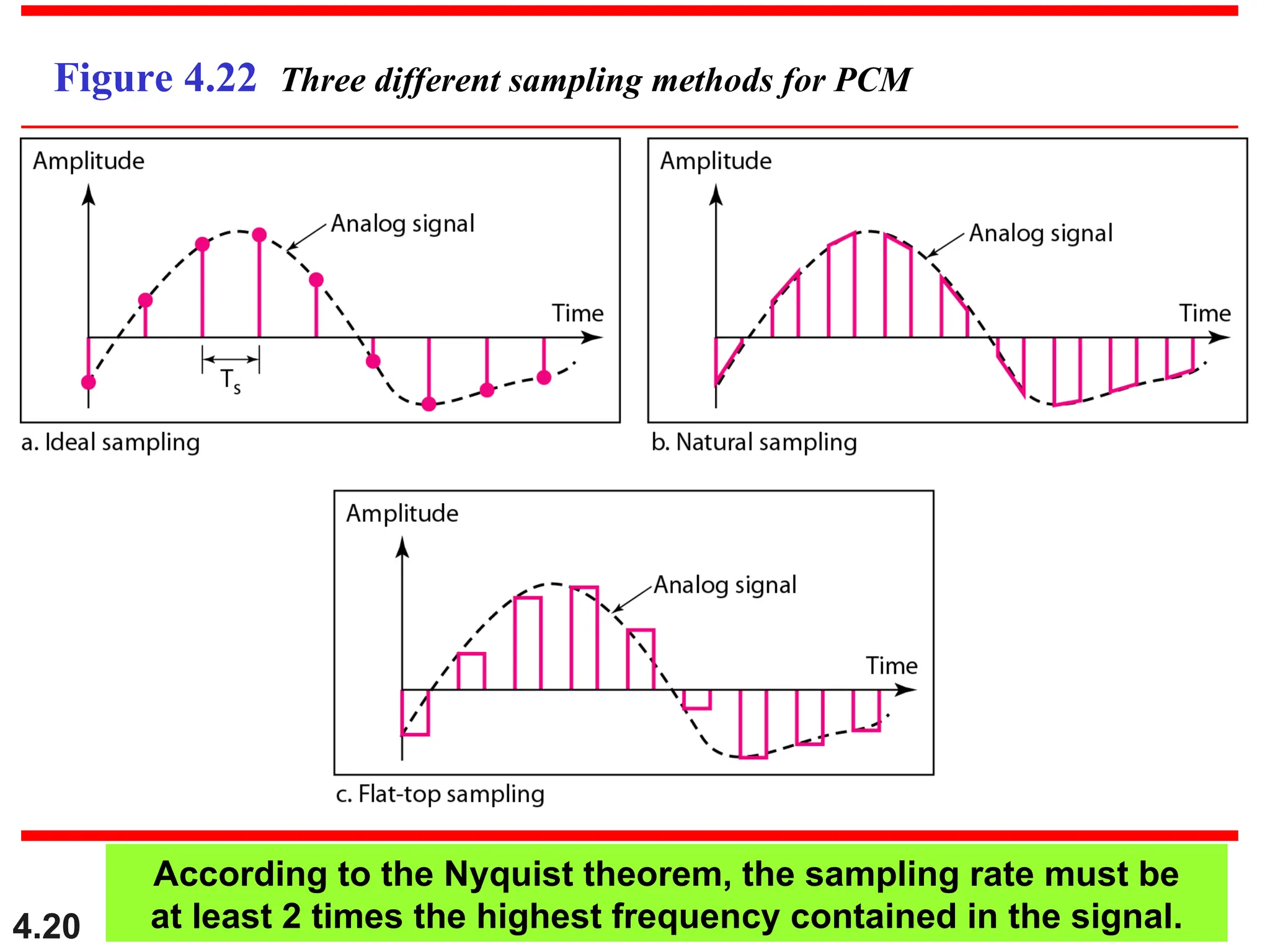
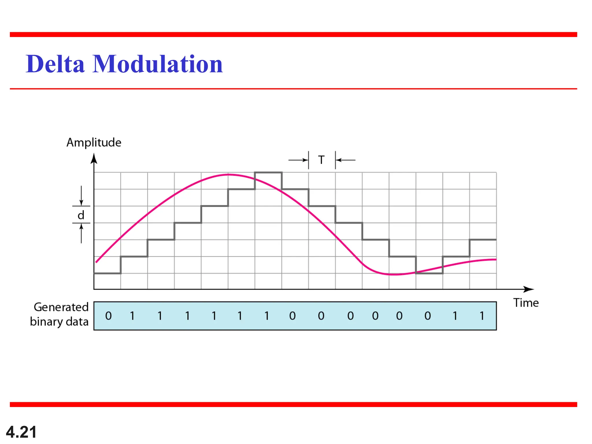
Figure 4.22 Threedifferent sampling methods for PCM
According to the Nyquist theorem, the sampling rate must be
at least 2 times the highest frequency contained in the signal.
4.23
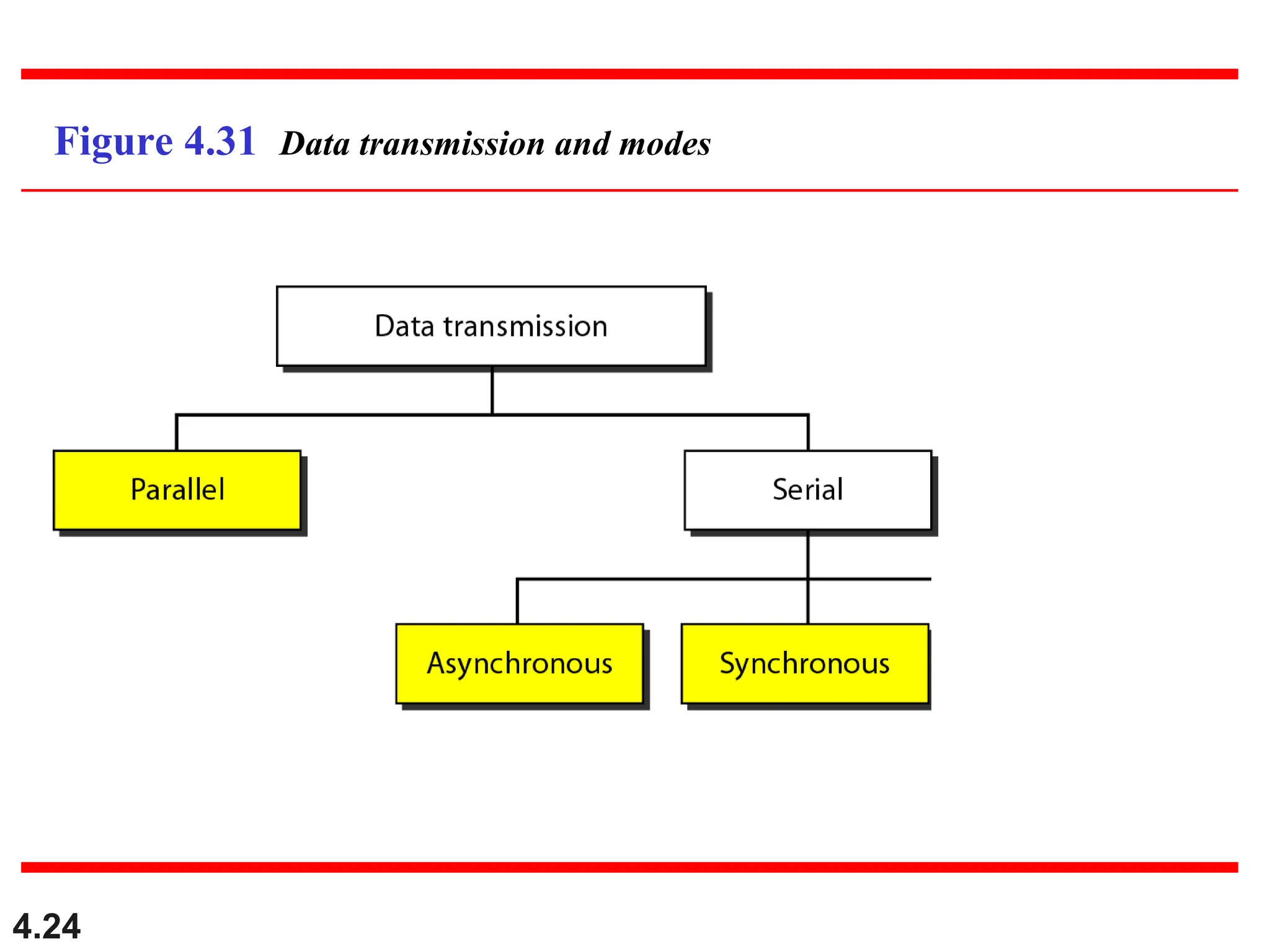
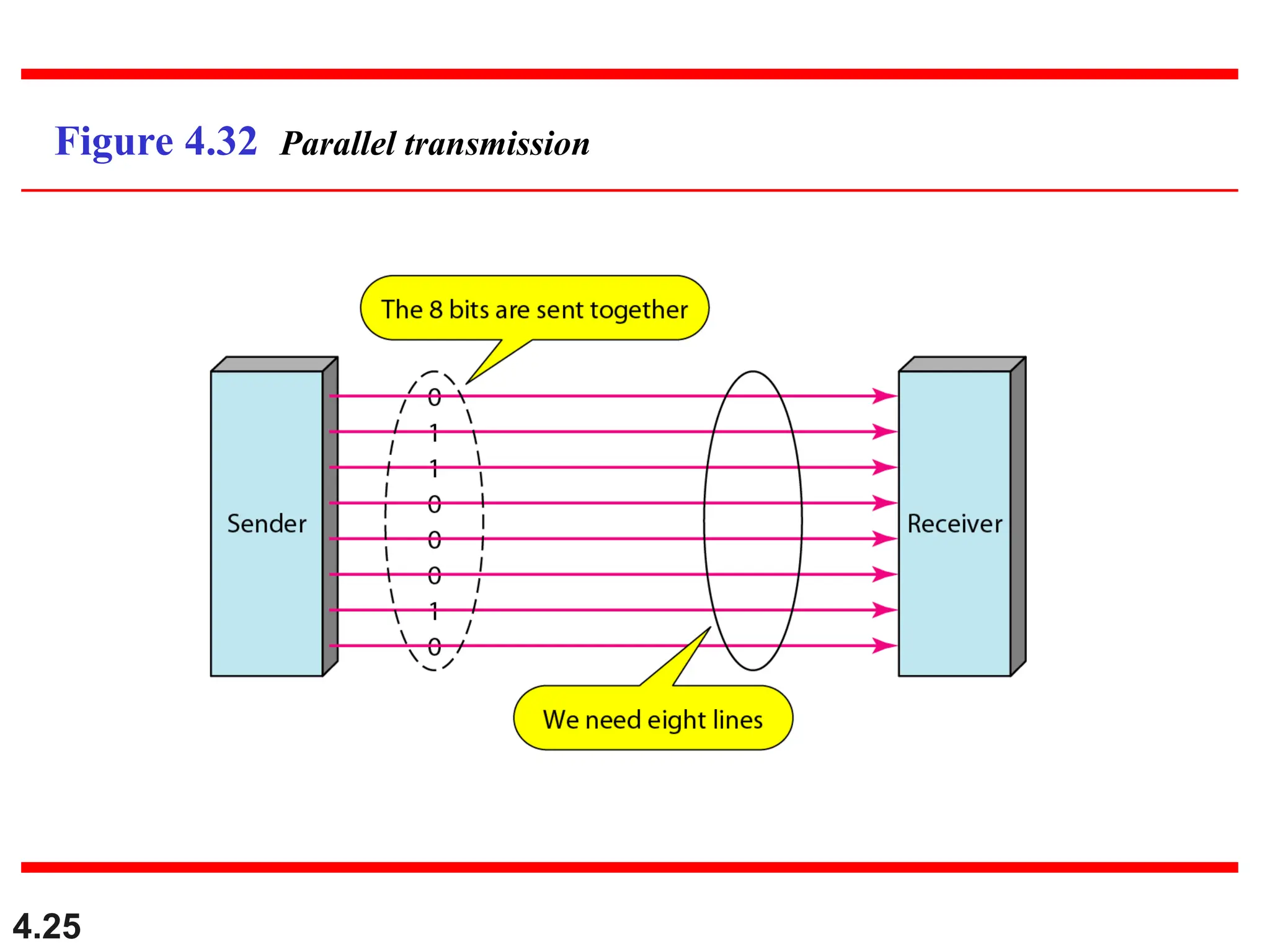
4-3 TRANSMISSION MODES
4-3TRANSMISSION MODES
The transmission of binary data across a link can be
The transmission of binary data across a link can be
accomplished in either parallel or serial mode. In
accomplished in either parallel or serial mode. In
parallel mode, multiple bits are sent with each clock
parallel mode, multiple bits are sent with each clock
tick. In serial mode, 1 bit is sent with each clock tick.
tick. In serial mode, 1 bit is sent with each clock tick.
While there is only one way to send parallel data, there
While there is only one way to send parallel data, there
are three subclasses of serial transmission:
are three subclasses of serial transmission:
asynchronous, and synchronous.
asynchronous, and synchronous.
Parallel Transmission
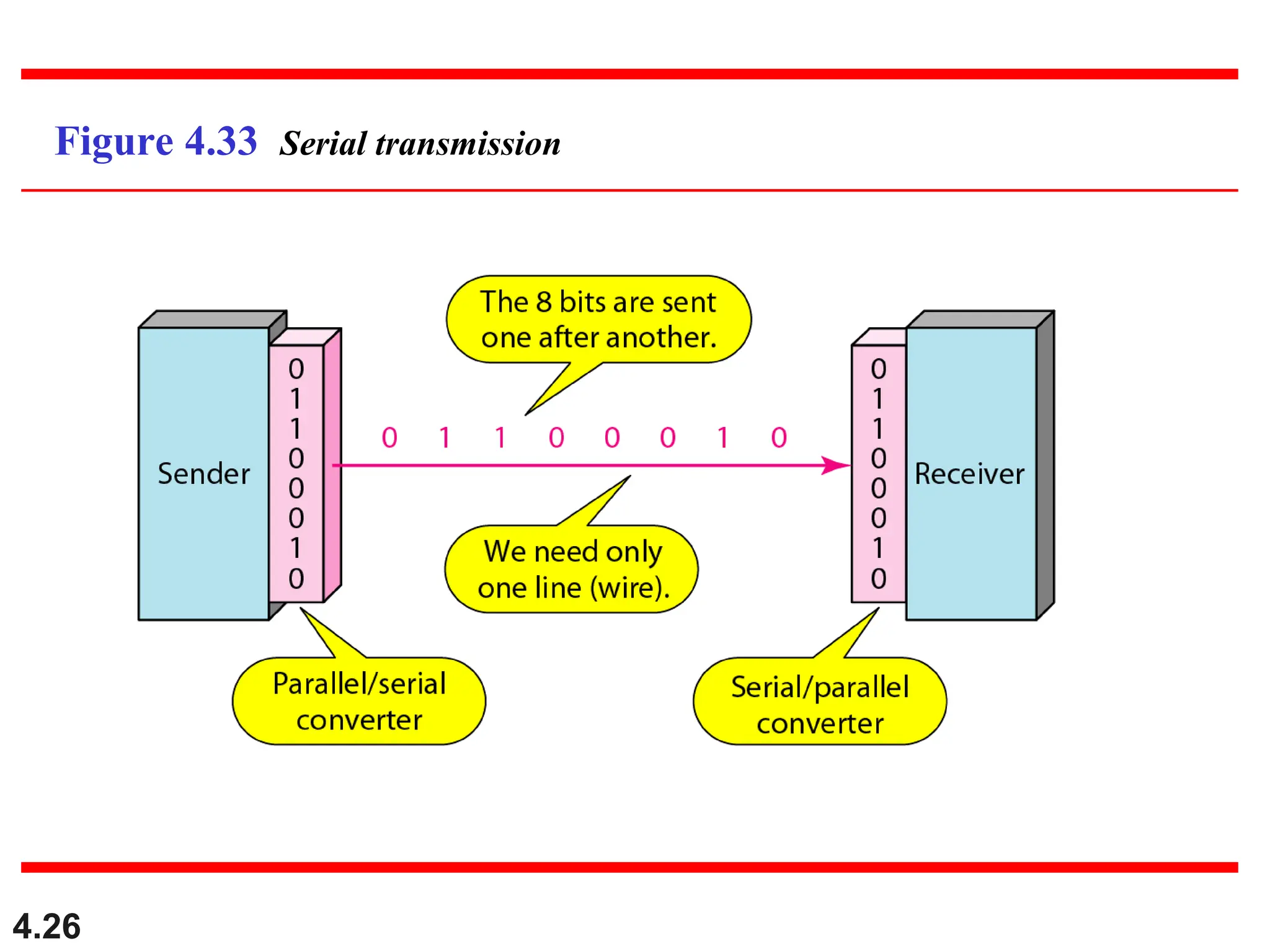
Serial Transmission
Topics discussed in this section:
Topics discussed in this section:
4.27
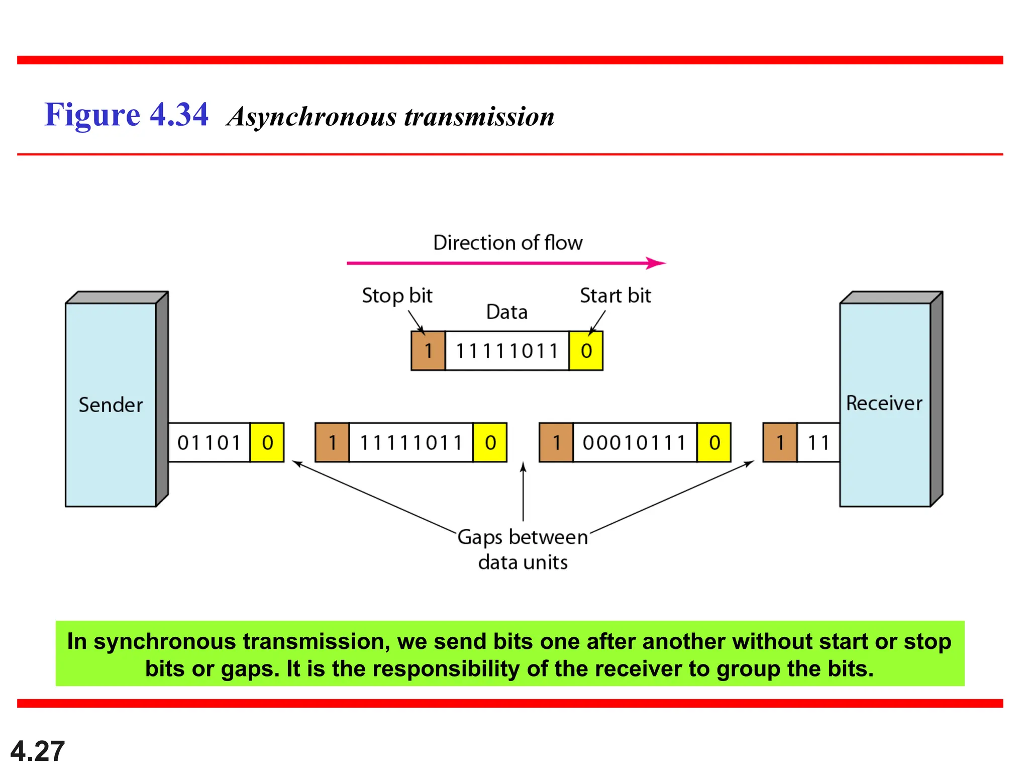
Figure 4.34 Asynchronoustransmission
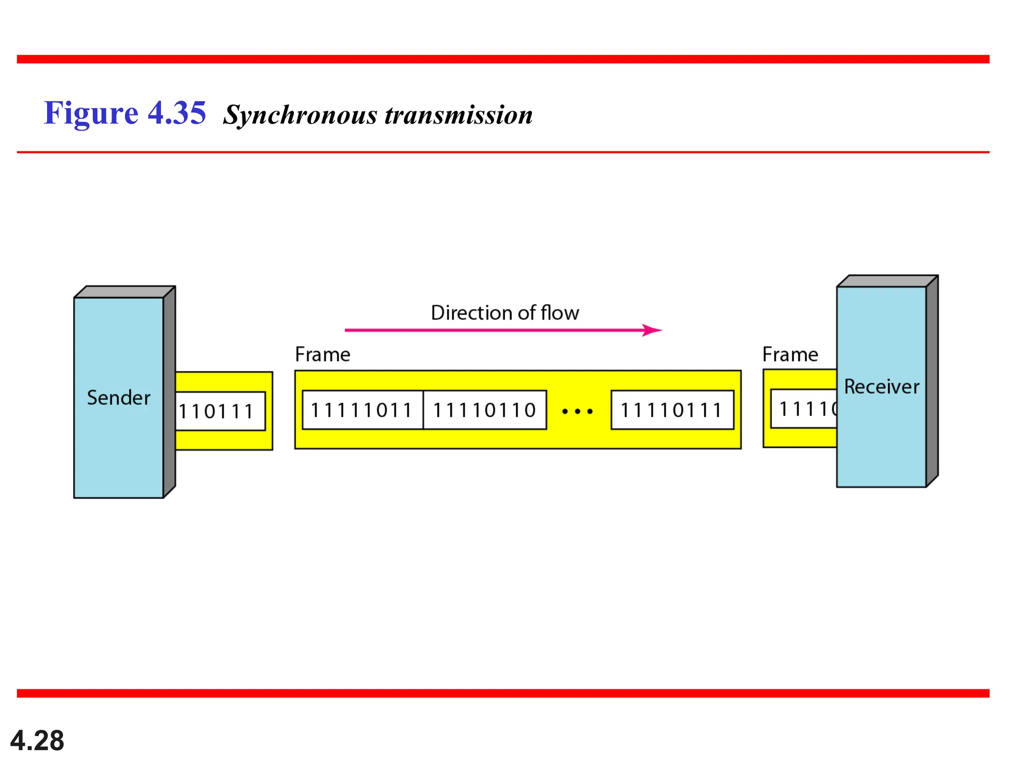
In synchronous transmission, we send bits one after another without start or stop
bits or gaps. It is the responsibility of the receiver to group the bits.