SlideShare a Scribd company logo
MODEL APPLICATION
Year Model Beginning Frame No.
2013 ZR800AD JKBZR800AADA00001
2013 ZR800BD
JKBZRCB1□DDA00001
JKBZR800ABDA00001
2013 ZR800CD JKBZR800CCDA00001
2013 ZR800DD JKBZR800CDDA00001
□:This digit in the frame number changes from one machine to another.
Part No.99924-1463-01 Printed in Japan
Z800
Z800 ABS
Motorcycle
Service Manual
This quick reference guide will assist
you in locating a desired topic or pro-
cedure.
•Bend the pages back to match the
black tab of the desired chapter num-
ber with the black tab on the edge at
each table of contents page.
•Refer to the sectional table of contents
for the exact pages to locate the spe-
cific topic required.
Quick Reference Guide
General Information 1 j
Periodic Maintenance 2 j
Fuel System (DFI) 3 j
Cooling System 4 j
Engine Top End 5 j
Clutch 6 j
Engine Lubrication System 7 j
Engine Removal/Installation 8 j
Crankshaft/Transmission 9 j
Wheels/Tires 10 j
Final Drive 11 j
Brakes 12 j
Suspension 13 j
Steering 14 j
Frame 15 j
Electrical System 16 j
Appendix 17 j
Z800
Z800 ABS
Motorcycle
Service Manual
All rights reserved. No parts of this publication may be reproduced, stored in a retrieval system, or
transmitted in any form or by any means, electronic mechanical photocopying, recording or otherwise,
without the prior written permission of Quality Assurance Division/Motorcycle & Engine Company/Kawasaki
Heavy Industries, Ltd., Japan.
No liability can be accepted for any inaccuracies or omissions in this publication, although every possible
care has been taken to make it as complete and accurate as possible.
The right is reserved to make changes at any time without prior notice and without incurring an obligation
to make such changes to products manufactured previously. See your Motorcycle dealer for the latest
information on product improvements incorporated after this publication.
All information contained in this publication is based on the latest product information available at the time
of publication. Illustrations and photographs in this publication are intended for reference use only and may
not depict actual model component parts.
© 2012 Kawasaki Heavy Industries, Ltd. First Edition (3) : Sep. 7, 2012
LIST OF ABBREVIATIONS
A ampere(s) in. inch(s)
ABDC after bottom dead center km/h kilometers per hour
ABS antilock brake system L liter(s)
AC alternating current LCD liquid crystal display
Ah ampere hour LED light emitting diode
ATDC after top dead center lb pound(s)
BBDC before bottom dead center m meter(s)
BDC bottom dead center min minute(s)
BTDC before top dead center mmHg millimeters of mercury
°C degree(s) Celsius mph miles per hour
cmHg centimeters of mercury N newton(s)
cu in cubic inch(s) oz ounce(s)
DC direct current Pa pascal(s)
DFI digital fuel injection PS horsepower
DOHC double overhead camshaft psi pound(s) per square inch
DOT department of transportation qt quart(s)
ECU electronic control unit r revolution
F farad(s) rpm revolution(s) per minute
°F degree(s) Fahrenheit s second(s)
ft foot, feet TDC top dead center
g gram(s) TIR total indicator reading
gal gallon(s) V volt(s)
h hour(s) W watt(s)
HP horsepower(s) Ω ohm(s)
IC integrated circuit
COUNTRY AND AREA CODES
AU Australia
WVTA
(FULL)
WVTA Model (Full Power)
BR Brazil
UK WVTA
(FULL)
WVTA Model (Left Side Traffic, Full
Power)
SEA-B2 Southeast Asia B2
WVTA
(78.2)
WVTA Model (78.2 kW Power)
Foreword
This manual is designed primarily for use by
trained mechanics in a properly equipped shop.
However, it contains enough detail and basic in-
formation to make it useful to the owner who de-
sires to perform his own basic maintenance and
repair work. A basic knowledge of mechanics,
the proper use of tools, and workshop proce-
dures must be understood in order to carry out
maintenance and repair satisfactorily. When-
ever the owner has insufficient experience or
doubts his ability to do the work, all adjust-
ments, maintenance, and repair should be car-
ried out only by qualified mechanics.
In order to perform the work efficiently and
to avoid costly mistakes, read the text, thor-
oughly familiarize yourself with the procedures
before starting work, and then do the work care-
fully in a clean area. Whenever special tools or
equipment are specified, do not use makeshift
tools or equipment. Precision measurements
can only be made if the proper instruments are
used, and the use of substitute tools may ad-
versely affect safe operation.
For the duration of the warranty period,
we recommend that all repairs and scheduled
maintenance be performed in accordance with
this service manual. Any owner maintenance or
repair procedure not performed in accordance
with this manual may void the warranty.
To get the longest life out of your vehicle.
•Follow the Periodic Maintenance Chart in the
Service Manual.
•Be alert for problems and non-scheduled
maintenance.
•Use proper tools and genuine Kawasaki Mo-
torcycle parts. Special tools, gauges, and
testers that are necessary when servicing
Kawasaki motorcycles are introduced by the
Service Manual. Genuine parts provided as
spare parts are listed in the Parts Catalog.
•Follow the procedures in this manual care-
fully. Don’t take shortcuts.
•Remember to keep complete records of main-
tenance and repair with dates and any new
parts installed.
How to Use This Manual
In this manual, the product is divided into
its major systems and these systems make up
the manual’s chapters. The Quick Reference
Guide shows you all of the product’s system
and assists in locating their chapters. Each
chapter in turn has its own comprehensive Ta-
ble of Contents.
For example, if you want stick coil information,
use the Quick Reference Guide to locate the
Electrical System chapter. Then, use the Table
of Contents on the first page of the chapter to
find the Stick Coil section.
Whenever you see symbols, heed their in-
structions! Always follow safe operating and
maintenance practices.
DANGER
DANGER indicates a hazardous situa-
tion which, if not avoided, will result in
death or serious injury.
WARNING
WARNING indicates a hazardous situa-
tion which, if not avoided, could result
in death or serious injury.
NOTICE
NOTICE is used to address practices not
related to personal injury.
This manual contains four more symbols
which will help you distinguish different types
of information.
NOTE
○This note symbol indicates points of par-
ticular interest for more efficient and con-
venient operation.
•Indicates a procedural step or work to be
done.
○Indicates a procedural sub-step or how to do
the work of the procedural step it follows. It
also precedes the text of a NOTE.
Indicates a conditional step or what action to
take based on the results of the test or inspec-
tion in the procedural step or sub-step it fol-
lows.
In most chapters an exploded view illustration
of the system components follows the Table of
Contents. In these illustrations you will find the
instructions indicating which parts require spec-
ified tightening torque, oil, grease or a locking
agent during assembly.
GENERAL INFORMATION 1-1
1
General Information
Table of Contents
Before Servicing ..................................................................................................................... 1-2
Model Identification................................................................................................................. 1-7
General Specifications............................................................................................................ 1-11
Unit Conversion Table ............................................................................................................ 1-14
1-2 GENERAL INFORMATION
Before Servicing
Before starting to perform an inspection service or carry out a disassembly and reassembly opera-
tion on a motorcycle, read the precautions given below. To facilitate actual operations, notes, illustra-
tions, photographs, cautions, and detailed descriptions have been included in each chapter wherever
necessary. This section explains the items that require particular attention during the removal and
reinstallation or disassembly and reassembly of general parts.
Especially note the following.
Battery Ground
Before completing any service on the motorcycle, discon-
nect the battery cables from the battery to prevent the en-
gine from accidentally turning over. Disconnect the ground
cable (–) first and then the positive (+). When completed
with the service, first connect the positive (+) cable to the
positive (+) terminal of the battery then the negative (–) ca-
ble to the negative terminal.
Edges of Parts
Lift large or heavy parts wearing gloves to prevent injury
from possible sharp edges on the parts.
Solvent
Use a high flash-point solvent when cleaning parts. High
flash-point solvent should be used according to directions
of the solvent manufacturer.
Cleaning Vehicle before Disassembly
Clean the vehicle thoroughly before disassembly. Dirt or
other foreign materials entering into sealed areas during ve-
hicle disassembly can cause excessive wear and decrease
performance of the vehicle.
GENERAL INFORMATION 1-3
Before Servicing
Arrangement and Cleaning of Removed Parts
Disassembled parts are easy to confuse. Arrange the
parts according to the order the parts were disassembled
and clean the parts in order prior to assembly.
Storage of Removed Parts
After all the parts including subassembly parts have been
cleaned, store the parts in a clean area. Put a clean cloth
or plastic sheet over the parts to protect from any foreign
materials that may collect before re-assembly.
Inspection
Reuse of worn or damaged parts may lead to serious ac-
cident. Visually inspect removed parts for corrosion, discol-
oration, or other damage. Refer to the appropriate sections
of this manual for service limits on individual parts. Replace
the parts if any damage has been found or if the part is be-
yond its service limit.
Replacement Parts
Replacement parts must be KAWASAKI genuine or
recommended by KAWASAKI. Gaskets, O-rings, oil seals,
grease seals, circlips, cotter pins or self-locking nuts must
be replaced with new ones whenever disassembled.
Assembly Order
In most cases assembly order is the reverse of disassem-
bly, however, if assembly order is provided in this Service
Manual, follow the procedures given.
1-4 GENERAL INFORMATION
Before Servicing
Tightening Sequence
Generally, when installing a part with several bolts, nuts,
or screws, start them all in their holes and tighten them to
a snug fit. Then tighten them according to the specified se-
quence to prevent case warpage or deformation which can
lead to malfunction. Conversely when loosening the bolts,
nuts, or screws, first loosen all of them by about a quar-
ter turn and then remove them. If the specified tightening
sequence is not indicated, tighten the fasteners alternating
diagonally.
Tightening Torque
Incorrect torque applied to a bolt, nut, or screw may
lead to serious damage. Tighten fasteners to the specified
torque using a good quality torque wrench.
Force
Use common sense during disassembly and assembly,
excessive force can cause expensive or hard to repair dam-
age. When necessary, remove screws that have a non
-permanent locking agent applied using an impact driver.
Use a plastic-faced mallet whenever tapping is necessary.
Gasket, O-ring
Hardening, shrinkage, or damage of both gaskets and
O-rings after disassembly can reduce sealing performance.
Remove old gaskets and clean the sealing surfaces thor-
oughly so that no gasket material or other material remains.
Install the new gaskets and replace the used O-rings when
re-assembling.
Liquid Gasket, Non-permanent Locking Agent
For applications that require Liquid Gasket or a
Non-Permanent Locking Agent, clean the surfaces so
that no oil residue remains before applying liquid gasket or
non-permanent locking agent. Do not apply them exces-
sively. Excessive application can clog oil passages and
cause serious damage.
GENERAL INFORMATION 1-5
Before Servicing
Press
For items such as bearings or oil seals that must be
pressed into place, apply small amount of oil to the con-
tact area. Be sure to maintain proper alignment and use
smooth movements when installing.
Ball Bearing and Needle Bearing
Do not remove pressed ball or needle unless removal is
absolutely necessary. Replace with new ones whenever
removed. Press bearings with the manufacturer and size
marks facing out. Press the bearing into place by putting
pressure on the correct bearing race as shown.
Pressing the incorrect race can cause pressure between
the inner and outer race and result in bearing damage.
Oil Seal, Grease Seal
Do not remove pressed oil or grease seals unless removal
is necessary. Replace with new ones whenever removed.
Press new oil seals with manufacture and size marks facing
out. Make sure the seal is aligned properly when installing.
Apply specified grease to the lip of seal before installing
the seal.
Circlips, Cotter Pins
Replace the circlips or cotter pins that were removed with
new ones. Take care not to open the clip excessively when
installing to prevent deformation.
1-6 GENERAL INFORMATION
Before Servicing
Lubrication
It is important to lubricate rotating or sliding parts during
assembly to minimize wear during initial operation. Lubri-
cation points are called out throughout this manual, apply
the specific oil or grease as specified.
Direction of Engine Rotation
When rotating the crankshaft by hand, the free play
amount of rotating direction will affect the adjustment. Ro-
tate the crankshaft to positive direction (clockwise viewed
from output side).
Electrical Wires
A two-color wire is identified first by the primary color and
then the stripe color. Unless instructed otherwise, electrical
wires must be connected to those of the same color.
Instrument
Use a meter that has enough accuracy for an accurate
measurement. Read the manufacture’s instructions thor-
oughly before using the meter. Incorrect values may lead
to improper adjustments.
GENERAL INFORMATION 1-7
Model Identification
ZR800AD (Europe) Left Side View
ZR800AD (Europe) Right Side View
1-8 GENERAL INFORMATION
Model Identification
ZR800BD (Europe) Left Side View
ZR800BD (Europe) Right Side View
GENERAL INFORMATION 1-9
Model Identification
ZR800CD Left Side View
ZR800CD Right Side View
Thank you very much for
your reading. Please Click
Here. Then Get COMPLETE
MANUAL. NO WAITING
NOTE:
If there is no response to
click on the link above,
please download the PDF
document first and then
click on it.
1-10 GENERAL INFORMATION
Model Identification
ZR800DD Left Side View
ZR800DD Right Side View
Frame Number Engine Number
GENERAL INFORMATION 1-11
General Specifications
Items ZR800AD/BD/CD/DD
Dimensions
Overall Length 2 100 mm (82.68 in.)
Overall Width 800 mm (31.50 in.)
Overall Height 1 050 mm (41.34 in.)
Wheelbase 1 445 mm (56.89 in.)
Road Clearance 150 mm (5.91 in.)
Seat Height 834 mm (32.83 in.)
Curb Mass:
ZR800A 229 kg (504.9 lb)
ZR800B 231 kg (509.4 lb)
ZR800C 226 kg (498.3 lb)
ZR800D 228 kg (502.7 lb)
Front:
ZR800A 116 kg (255.8 lb)
ZR800B 117 kg (258.0 lb)
ZR800C 114 kg (251.4 lb)
ZR800D 115 kg (253.6 lb)
Rear:
ZR800A 113 kg (249.2 lb)
ZR800B 114 kg (251.4 lb)
ZR800C 112 kg (247.0 lb)
ZR800D 113 kg (249.2 lb)
Fuel Tank Capacity 17 L (4.5 US gal.)
Performance
Minimum Turning Radius 3.0 m (9.8 ft)
Engine
Type 4-stroke, DOHC, 4-cylinder
Cooling System Liquid-cooled
Bore and Stroke 71.0 × 50.9 mm (2.80 × 2.00 in.)
Displacement 806 cm³ (49.18 cu in.)
Compression Ratio 11.9 : 1
Maximum Horsepower:
ZR800A/B 83.0 kW (113 PS) at 10 200 r/min (rpm)
WVTA (78.2) 78.2 kW (106 PS) at 10 000 r/min (rpm)
ZR800C/D 70.0 kW (95.2 PS) at 9 500 r/min (rpm)
Maximum Torque:
ZR800A/B 83.0 N·m (8.5 kgf·m, 61 ft·lb) at 8 000 r/min (rpm)
WVTA (78.2) 80.5 N·m (8.2 kgf·m, 59 ft·lb) at 8 000 r/min (rpm)
ZR800C/D 76.0 N·m (7.7 kgf·m, 56 ft·lb) at 8 000 r/min (rpm)
Fuel System FI (Fuel Injection) MIKUNI 34 EHDW × 4
Starting System Electric starter
Ignition System Battery and coil (transistorized)
Timing Advance Electronically advanced (digital igniter)
Ignition Timing From 10° BTDC at 1 100 r/min (rpm) to 37° BTDC
at 5 000 r/min (rpm)
1-12 GENERAL INFORMATION
General Specifications
Items ZR800AD/BD/CD/DD
Spark Plug NGK CR9EK, ND U27ETR
Cylinder Numbering Method Left to right, 1-2-3-4
Firing Order 1-2-4-3
Valve Timing:
Intake:
Open 38° BTDC
Close 66° ABDC
Duration 284°
Exhaust:
Open 51° BBDC
Close 25° ATDC
Duration 256°
Lubrication System Forced lubrication (wet sump)
Engine Oil:
Type API SG, SH, SJ, SL or SM with JASO MA, MA1 or MA2
Viscosity SAE 10W-40
Capacity 3.8 L (4.0 US qt)
Drive Train
Primary Reduction System:
Type Gear
Reduction Ratio 1.714 (84/49)
Clutch Type Wet multi disc
Transmission:
Type 6-speed, constant mesh, return shift
Gear Ratios:
1st 2.571 (36/14)
2nd 1.941 (33/17)
3rd 1.556 (28/18)
4th 1.333 (28/21)
5th 1.200 (24/20)
6th 1.095 (23/21)
Final Drive System:
Type Chain drive
Reduction Ratio 3.000 (45/15)
Overall Drive Ratio 5.633 at Top gear
Frame
Type Tubular, diamond
Caster (Rake Angle) 24°
Trail 98 mm (3.86 in.)
Front Tire:
Type Tubeless
Size 120/70ZR17 M/C (58W)
Rim Size J17M/C × MT3.50
GENERAL INFORMATION 1-13
General Specifications
Items ZR800AD/BD/CD/DD
Rear Tire:
Type Tubeless
Size 180/55ZR17 M/C (73W)
Rim Size J17M/C × MT5.50
Front Suspension:
Type Telescopic fork
Wheel Travel 120 mm (4.72 in.)
Rear Suspension:
Type Swingarm (uni-trak)
Wheel Travel 137 mm (5.39 in.)
Brake Type:
Front Dual discs
Rear Single disc
Electrical Equipment
Battery 12 V 8 Ah
Headlight:
Type Semi-sealed beam
Bulb:
High Beam 12 V 55 W × 2
Low Beam 12 V 55 W
Tail/Brake Light LED
Alternator:
Type Three-phase AC
Rated Output 30.1 A/14.0 V at 5 000 r/min (rpm)
Specifications are subject to change without notice, and may not apply to every country.
1-14 GENERAL INFORMATION
Unit Conversion Table
Prefixes for Units:
Prefix Symbol Power
mega M × 1 000 000
kilo k × 1 000
centi c × 0.01
milli m × 0.001
micro µ × 0.000001
Units of Mass:
kg × 2.205 = lb
g × 0.03527 = oz
Units of Volume:
L × 0.2642 = gal (US)
L × 0.2200 = gal (IMP)
L × 1.057 = qt (US)
L × 0.8799 = qt (IMP)
L × 2.113 = pint (US)
L × 1.816 = pint (IMP)
mL × 0.03381 = oz (US)
mL × 0.02816 = oz (IMP)
mL × 0.06102 = cu in.
Units of Force:
N × 0.1020 = kg
N × 0.2248 = lb
kg × 9.807 = N
kg × 2.205 = lb
Units of Length:
km × 0.6214 = mile
m × 3.281 = ft
mm × 0.03937 = in.
Units of Torque:
N·m × 0.1020 = kgf·m
N·m × 0.7376 = ft·lb
N·m × 8.851 = in·lb
kgf·m × 9.807 = N·m
kgf·m × 7.233 = ft·lb
kgf·m × 86.80 = in·lb
Units of Pressure:
kPa × 0.01020 = kgf/cm²
kPa × 0.1450 = psi
kPa × 0.7501 = cmHg
kgf/cm² × 98.07 = kPa
kgf/cm² × 14.22 = psi
cmHg × 1.333 = kPa
Units of Speed:
km/h × 0.6214 = mph
Units of Power:
kW × 1.360 = PS
kW × 1.341 = HP
PS × 0.7355 = kW
PS × 0.9863 = HP
Units of Temperature:
PERIODIC MAINTENANCE 2-1
2
Periodic Maintenance
Table of Contents
Periodic Maintenance Chart ................................................................................................... 2-3
Torque and Locking Agent...................................................................................................... 2-5
Specifications ......................................................................................................................... 2-11
Special Tools .......................................................................................................................... 2-13
Periodic Maintenance Procedures.......................................................................................... 2-14
Fuel System (DFI)................................................................................................................ 2-14
Air Cleaner Element Cleaning........................................................................................... 2-14
Air Cleaner Element Replacement.................................................................................... 2-14
Idle Speed Inspection ....................................................................................................... 2-16
Idle Speed Adjustment...................................................................................................... 2-16
Throttle Control System Inspection................................................................................... 2-16
Engine Vacuum Synchronization Inspection..................................................................... 2-17
Fuel System...................................................................................................................... 2-20
Fuel Hose Replacement ................................................................................................... 2-22
Cooling System.................................................................................................................... 2-25
Coolant Level Inspection................................................................................................... 2-25
Cooling System................................................................................................................. 2-25
Coolant Change................................................................................................................ 2-25
Water Hose and O-ring Replacement............................................................................... 2-28
Engine Top End ................................................................................................................... 2-28
Valve Clearance Inspection .............................................................................................. 2-28
Valve Clearance Adjustment............................................................................................. 2-30
Air Suction System Damage Inspection............................................................................ 2-33
Clutch................................................................................................................................... 2-33
Clutch Operation Inspection.............................................................................................. 2-33
Engine Lubrication System.................................................................................................. 2-34
Engine Oil Change............................................................................................................ 2-34
Oil Filter Replacement ...................................................................................................... 2-35
Wheels/Tires........................................................................................................................ 2-36
Air Pressure Inspection..................................................................................................... 2-36
Wheels and Tires .............................................................................................................. 2-36
Wheel Bearing Damage Inspection .................................................................................. 2-37
Final Drive............................................................................................................................ 2-38
Drive Chain Lubrication Condition Inspection................................................................... 2-38
Drive Chain Slack Inspection............................................................................................ 2-38
Drive Chain Slack Adjustment .......................................................................................... 2-39
Wheel Alignment Inspection ............................................................................................. 2-40
Drive Chain Wear Inspection ............................................................................................ 2-40
Chain Guide Wear Inspection........................................................................................... 2-41
Brakes.................................................................................................................................. 2-42
Brake System.................................................................................................................... 2-42
Brake Fluid Level Inspection............................................................................................. 2-43
Brake Fluid Change .......................................................................................................... 2-44
Brake Hose and Pipe Replacement.................................................................................. 2-46
Master Cylinder Rubber Parts Replacement .................................................................... 2-47
Caliper Rubber Parts Replacement .................................................................................. 2-48
Brake Pad Wear Inspection .............................................................................................. 2-52
Brake Light Switch Operation Inspection.......................................................................... 2-52
Suspension.......................................................................................................................... 2-53
Suspension System .......................................................................................................... 2-53

More Related Content

What's hot

Yale a249 mp20 pallet truck service repair manual
Yale a249 mp20 pallet truck service repair manualYale a249 mp20 pallet truck service repair manual
Yale a249 mp20 pallet truck service repair manual
fjsekkskem
 
New holland br6090 combi service repair manual
New holland br6090 combi service repair manualNew holland br6090 combi service repair manual
New holland br6090 combi service repair manual
uujjfjjkskmme
 
JCB 165, 165HF ROBOT Service Repair Manual SN678000 Onwards
JCB 165, 165HF ROBOT Service Repair Manual SN678000 OnwardsJCB 165, 165HF ROBOT Service Repair Manual SN678000 Onwards
JCB 165, 165HF ROBOT Service Repair Manual SN678000 Onwards
yjshefjnd jkdfjmmd
 
CASE 580N TRACTOR LOADER BACKHOE Service Repair Manual
CASE 580N TRACTOR LOADER BACKHOE Service Repair ManualCASE 580N TRACTOR LOADER BACKHOE Service Repair Manual
CASE 580N TRACTOR LOADER BACKHOE Service Repair Manual
uekdjkm jksemmd
 
YALE G807 ERP18VT LIFT TRUCK (EUROPE) Service Repair Manual
YALE G807 ERP18VT LIFT TRUCK (EUROPE) Service Repair ManualYALE G807 ERP18VT LIFT TRUCK (EUROPE) Service Repair Manual
YALE G807 ERP18VT LIFT TRUCK (EUROPE) Service Repair Manual
yehnmdm jnkmem
 
2010 YAMAHA F300CA 4-STROKE OUTBOARD Service Repair Manual SN:1000001 and up
2010 YAMAHA F300CA 4-STROKE OUTBOARD Service Repair Manual SN:1000001 and up2010 YAMAHA F300CA 4-STROKE OUTBOARD Service Repair Manual SN:1000001 and up
2010 YAMAHA F300CA 4-STROKE OUTBOARD Service Repair Manual SN:1000001 and up
jksemd jksemm
 
X-Smart Dentsly Catalogue
X-Smart Dentsly CatalogueX-Smart Dentsly Catalogue
X-Smart Dentsly Catalogue
vlnkhn
 
2010 YAMAHA F300CA 4-STROKE OUTBOARD Service Repair Manual SN:1000001 and up
2010 YAMAHA F300CA 4-STROKE OUTBOARD Service Repair Manual SN:1000001 and up2010 YAMAHA F300CA 4-STROKE OUTBOARD Service Repair Manual SN:1000001 and up
2010 YAMAHA F300CA 4-STROKE OUTBOARD Service Repair Manual SN:1000001 and up
ufjjdkkkesmdmm
 
Yale a245 (mpb045 vg) hand truck & pallet truck service repair manual
Yale a245 (mpb045 vg) hand truck & pallet truck service repair manualYale a245 (mpb045 vg) hand truck & pallet truck service repair manual
Yale a245 (mpb045 vg) hand truck & pallet truck service repair manual
jfskemsemm
 
Toyota 7 fbcu45 forklift service repair manual
Toyota 7 fbcu45 forklift service repair manualToyota 7 fbcu45 forklift service repair manual
Toyota 7 fbcu45 forklift service repair manual
fjjsekdmme
 
Toyota 7 fbcu25 forklift service repair manual
Toyota 7 fbcu25 forklift service repair manualToyota 7 fbcu25 forklift service repair manual
Toyota 7 fbcu25 forklift service repair manual
fjjskdmnenemm
 
Toyota 30 7 fbcu45 forklift service repair manual
Toyota 30 7 fbcu45 forklift service repair manualToyota 30 7 fbcu45 forklift service repair manual
Toyota 30 7 fbcu45 forklift service repair manual
jjfjsekksemm
 
Toyota 30 7 fbcu25 forklift service repair manual
Toyota 30 7 fbcu25 forklift service repair manualToyota 30 7 fbcu25 forklift service repair manual
Toyota 30 7 fbcu25 forklift service repair manual
fhjsjkdmemm
 
Toyota 7 fbcu30 forklift service repair manual
Toyota 7 fbcu30 forklift service repair manualToyota 7 fbcu30 forklift service repair manual
Toyota 7 fbcu30 forklift service repair manual
fjjskekdmmme
 
2008 TOYOTA COROLLA Service Repair Manual
2008 TOYOTA COROLLA Service Repair Manual2008 TOYOTA COROLLA Service Repair Manual
2008 TOYOTA COROLLA Service Repair Manual
fujjsekfkekmd
 
Kubota d1005 e4 b diesel engine service repair manual
Kubota d1005 e4 b diesel engine service repair manualKubota d1005 e4 b diesel engine service repair manual
Kubota d1005 e4 b diesel engine service repair manual
fiskefksjemkm
 

What's hot (16)

Yale a249 mp20 pallet truck service repair manual
Yale a249 mp20 pallet truck service repair manualYale a249 mp20 pallet truck service repair manual
Yale a249 mp20 pallet truck service repair manual
 
New holland br6090 combi service repair manual
New holland br6090 combi service repair manualNew holland br6090 combi service repair manual
New holland br6090 combi service repair manual
 
JCB 165, 165HF ROBOT Service Repair Manual SN678000 Onwards
JCB 165, 165HF ROBOT Service Repair Manual SN678000 OnwardsJCB 165, 165HF ROBOT Service Repair Manual SN678000 Onwards
JCB 165, 165HF ROBOT Service Repair Manual SN678000 Onwards
 
CASE 580N TRACTOR LOADER BACKHOE Service Repair Manual
CASE 580N TRACTOR LOADER BACKHOE Service Repair ManualCASE 580N TRACTOR LOADER BACKHOE Service Repair Manual
CASE 580N TRACTOR LOADER BACKHOE Service Repair Manual
 
YALE G807 ERP18VT LIFT TRUCK (EUROPE) Service Repair Manual
YALE G807 ERP18VT LIFT TRUCK (EUROPE) Service Repair ManualYALE G807 ERP18VT LIFT TRUCK (EUROPE) Service Repair Manual
YALE G807 ERP18VT LIFT TRUCK (EUROPE) Service Repair Manual
 
2010 YAMAHA F300CA 4-STROKE OUTBOARD Service Repair Manual SN:1000001 and up
2010 YAMAHA F300CA 4-STROKE OUTBOARD Service Repair Manual SN:1000001 and up2010 YAMAHA F300CA 4-STROKE OUTBOARD Service Repair Manual SN:1000001 and up
2010 YAMAHA F300CA 4-STROKE OUTBOARD Service Repair Manual SN:1000001 and up
 
X-Smart Dentsly Catalogue
X-Smart Dentsly CatalogueX-Smart Dentsly Catalogue
X-Smart Dentsly Catalogue
 
2010 YAMAHA F300CA 4-STROKE OUTBOARD Service Repair Manual SN:1000001 and up
2010 YAMAHA F300CA 4-STROKE OUTBOARD Service Repair Manual SN:1000001 and up2010 YAMAHA F300CA 4-STROKE OUTBOARD Service Repair Manual SN:1000001 and up
2010 YAMAHA F300CA 4-STROKE OUTBOARD Service Repair Manual SN:1000001 and up
 
Yale a245 (mpb045 vg) hand truck & pallet truck service repair manual
Yale a245 (mpb045 vg) hand truck & pallet truck service repair manualYale a245 (mpb045 vg) hand truck & pallet truck service repair manual
Yale a245 (mpb045 vg) hand truck & pallet truck service repair manual
 
Toyota 7 fbcu45 forklift service repair manual
Toyota 7 fbcu45 forklift service repair manualToyota 7 fbcu45 forklift service repair manual
Toyota 7 fbcu45 forklift service repair manual
 
Toyota 7 fbcu25 forklift service repair manual
Toyota 7 fbcu25 forklift service repair manualToyota 7 fbcu25 forklift service repair manual
Toyota 7 fbcu25 forklift service repair manual
 
Toyota 30 7 fbcu45 forklift service repair manual
Toyota 30 7 fbcu45 forklift service repair manualToyota 30 7 fbcu45 forklift service repair manual
Toyota 30 7 fbcu45 forklift service repair manual
 
Toyota 30 7 fbcu25 forklift service repair manual
Toyota 30 7 fbcu25 forklift service repair manualToyota 30 7 fbcu25 forklift service repair manual
Toyota 30 7 fbcu25 forklift service repair manual
 
Toyota 7 fbcu30 forklift service repair manual
Toyota 7 fbcu30 forklift service repair manualToyota 7 fbcu30 forklift service repair manual
Toyota 7 fbcu30 forklift service repair manual
 
2008 TOYOTA COROLLA Service Repair Manual
2008 TOYOTA COROLLA Service Repair Manual2008 TOYOTA COROLLA Service Repair Manual
2008 TOYOTA COROLLA Service Repair Manual
 
Kubota d1005 e4 b diesel engine service repair manual
Kubota d1005 e4 b diesel engine service repair manualKubota d1005 e4 b diesel engine service repair manual
Kubota d1005 e4 b diesel engine service repair manual
 

More from fjjskeknjufksemm

Kioti daedong ck35 tractor service repair manual
Kioti daedong ck35 tractor service repair manualKioti daedong ck35 tractor service repair manual
Kioti daedong ck35 tractor service repair manual
fjjskeknjufksemm
 
Jcb vibromax 405 single drum roller service repair manual
Jcb vibromax 405 single drum roller service repair manualJcb vibromax 405 single drum roller service repair manual
Jcb vibromax 405 single drum roller service repair manual
fjjskeknjufksemm
 
Yamaha outboard 40 veto, 40tr service repair manual l 544974
Yamaha outboard 40 veto, 40tr service repair manual l 544974  Yamaha outboard 40 veto, 40tr service repair manual l 544974
Yamaha outboard 40 veto, 40tr service repair manual l 544974
fjjskeknjufksemm
 
Yamaha g9 ej golf cart service repair manual
Yamaha g9 ej golf cart service repair manualYamaha g9 ej golf cart service repair manual
Yamaha g9 ej golf cart service repair manual
fjjskeknjufksemm
 
Yale c875 gtp20 vx lift truck service repair manual
Yale c875 gtp20 vx lift truck service repair manualYale c875 gtp20 vx lift truck service repair manual
Yale c875 gtp20 vx lift truck service repair manual
fjjskeknjufksemm
 
Yale a909 gdp90 vx lift truck service repair manual
Yale a909 gdp90 vx lift truck service repair manualYale a909 gdp90 vx lift truck service repair manual
Yale a909 gdp90 vx lift truck service repair manual
fjjskeknjufksemm
 
Perkins 1600 series industrial engine (xgf) service repair manual
Perkins 1600 series industrial engine (xgf) service repair manualPerkins 1600 series industrial engine (xgf) service repair manual
Perkins 1600 series industrial engine (xgf) service repair manual
fjjskeknjufksemm
 
Perkins 1600 series industrial engine (xga ) service repair manual
Perkins 1600 series industrial engine (xga ) service repair manualPerkins 1600 series industrial engine (xga ) service repair manual
Perkins 1600 series industrial engine (xga ) service repair manual
fjjskeknjufksemm
 
Perkins 1200 series 1206 e e70tta industrial engine service repair manual
Perkins 1200 series 1206 e e70tta industrial engine service repair manualPerkins 1200 series 1206 e e70tta industrial engine service repair manual
Perkins 1200 series 1206 e e70tta industrial engine service repair manual
fjjskeknjufksemm
 
Daewoo doosan solar 030 plus mini crawler excavator parts catalogue manual (s...
Daewoo doosan solar 030 plus mini crawler excavator parts catalogue manual (s...Daewoo doosan solar 030 plus mini crawler excavator parts catalogue manual (s...
Daewoo doosan solar 030 plus mini crawler excavator parts catalogue manual (s...
fjjskeknjufksemm
 
Daewoo doosan solar 015 plus mini crawler excavator parts catalogue manual (s...
Daewoo doosan solar 015 plus mini crawler excavator parts catalogue manual (s...Daewoo doosan solar 015 plus mini crawler excavator parts catalogue manual (s...
Daewoo doosan solar 015 plus mini crawler excavator parts catalogue manual (s...
fjjskeknjufksemm
 
Daewoo doosan solar 015 plus s018 vt mini crawler excavator parts catalogue ...
Daewoo doosan solar 015 plus  s018 vt mini crawler excavator parts catalogue ...Daewoo doosan solar 015 plus  s018 vt mini crawler excavator parts catalogue ...
Daewoo doosan solar 015 plus s018 vt mini crawler excavator parts catalogue ...
fjjskeknjufksemm
 
Daewoo doosan solar 015 mini crawler excavator parts catalogue manual
Daewoo doosan solar 015 mini crawler excavator parts catalogue manualDaewoo doosan solar 015 mini crawler excavator parts catalogue manual
Daewoo doosan solar 015 mini crawler excavator parts catalogue manual
fjjskeknjufksemm
 
Daewoo doosan solar 010 mini crawler excavator parts catalogue manual (sn 200...
Daewoo doosan solar 010 mini crawler excavator parts catalogue manual (sn 200...Daewoo doosan solar 010 mini crawler excavator parts catalogue manual (sn 200...
Daewoo doosan solar 010 mini crawler excavator parts catalogue manual (sn 200...
fjjskeknjufksemm
 
Daewoo doosan solar 010 mini crawler excavator parts catalogue manual
Daewoo doosan solar 010 mini crawler excavator parts catalogue manualDaewoo doosan solar 010 mini crawler excavator parts catalogue manual
Daewoo doosan solar 010 mini crawler excavator parts catalogue manual
fjjskeknjufksemm
 
Daewoo doosan mt41 moxy articulated dump truck parts catalogue manual
Daewoo doosan mt41 moxy articulated dump truck parts catalogue manualDaewoo doosan mt41 moxy articulated dump truck parts catalogue manual
Daewoo doosan mt41 moxy articulated dump truck parts catalogue manual
fjjskeknjufksemm
 
Daewoo doosan mt40 b moxy articulated dump truck parts catalogue manual
Daewoo doosan mt40 b moxy articulated dump truck parts catalogue manualDaewoo doosan mt40 b moxy articulated dump truck parts catalogue manual
Daewoo doosan mt40 b moxy articulated dump truck parts catalogue manual
fjjskeknjufksemm
 
Daewoo doosan mt36 moxy articulated dump truck parts catalogue manual sn 41...
Daewoo doosan mt36 moxy articulated dump truck parts catalogue manual   sn 41...Daewoo doosan mt36 moxy articulated dump truck parts catalogue manual   sn 41...
Daewoo doosan mt36 moxy articulated dump truck parts catalogue manual sn 41...
fjjskeknjufksemm
 
Daewoo doosan mt36 moxy articulated dump truck parts catalogue manual
Daewoo doosan mt36 moxy articulated dump truck parts catalogue manualDaewoo doosan mt36 moxy articulated dump truck parts catalogue manual
Daewoo doosan mt36 moxy articulated dump truck parts catalogue manual
fjjskeknjufksemm
 
Daewoo doosan mt31 moxy articulated dump truck parts catalogue manual sn 71...
Daewoo doosan mt31 moxy articulated dump truck parts catalogue manual   sn 71...Daewoo doosan mt31 moxy articulated dump truck parts catalogue manual   sn 71...
Daewoo doosan mt31 moxy articulated dump truck parts catalogue manual sn 71...
fjjskeknjufksemm
 

More from fjjskeknjufksemm (20)

Kioti daedong ck35 tractor service repair manual
Kioti daedong ck35 tractor service repair manualKioti daedong ck35 tractor service repair manual
Kioti daedong ck35 tractor service repair manual
 
Jcb vibromax 405 single drum roller service repair manual
Jcb vibromax 405 single drum roller service repair manualJcb vibromax 405 single drum roller service repair manual
Jcb vibromax 405 single drum roller service repair manual
 
Yamaha outboard 40 veto, 40tr service repair manual l 544974
Yamaha outboard 40 veto, 40tr service repair manual l 544974  Yamaha outboard 40 veto, 40tr service repair manual l 544974
Yamaha outboard 40 veto, 40tr service repair manual l 544974
 
Yamaha g9 ej golf cart service repair manual
Yamaha g9 ej golf cart service repair manualYamaha g9 ej golf cart service repair manual
Yamaha g9 ej golf cart service repair manual
 
Yale c875 gtp20 vx lift truck service repair manual
Yale c875 gtp20 vx lift truck service repair manualYale c875 gtp20 vx lift truck service repair manual
Yale c875 gtp20 vx lift truck service repair manual
 
Yale a909 gdp90 vx lift truck service repair manual
Yale a909 gdp90 vx lift truck service repair manualYale a909 gdp90 vx lift truck service repair manual
Yale a909 gdp90 vx lift truck service repair manual
 
Perkins 1600 series industrial engine (xgf) service repair manual
Perkins 1600 series industrial engine (xgf) service repair manualPerkins 1600 series industrial engine (xgf) service repair manual
Perkins 1600 series industrial engine (xgf) service repair manual
 
Perkins 1600 series industrial engine (xga ) service repair manual
Perkins 1600 series industrial engine (xga ) service repair manualPerkins 1600 series industrial engine (xga ) service repair manual
Perkins 1600 series industrial engine (xga ) service repair manual
 
Perkins 1200 series 1206 e e70tta industrial engine service repair manual
Perkins 1200 series 1206 e e70tta industrial engine service repair manualPerkins 1200 series 1206 e e70tta industrial engine service repair manual
Perkins 1200 series 1206 e e70tta industrial engine service repair manual
 
Daewoo doosan solar 030 plus mini crawler excavator parts catalogue manual (s...
Daewoo doosan solar 030 plus mini crawler excavator parts catalogue manual (s...Daewoo doosan solar 030 plus mini crawler excavator parts catalogue manual (s...
Daewoo doosan solar 030 plus mini crawler excavator parts catalogue manual (s...
 
Daewoo doosan solar 015 plus mini crawler excavator parts catalogue manual (s...
Daewoo doosan solar 015 plus mini crawler excavator parts catalogue manual (s...Daewoo doosan solar 015 plus mini crawler excavator parts catalogue manual (s...
Daewoo doosan solar 015 plus mini crawler excavator parts catalogue manual (s...
 
Daewoo doosan solar 015 plus s018 vt mini crawler excavator parts catalogue ...
Daewoo doosan solar 015 plus  s018 vt mini crawler excavator parts catalogue ...Daewoo doosan solar 015 plus  s018 vt mini crawler excavator parts catalogue ...
Daewoo doosan solar 015 plus s018 vt mini crawler excavator parts catalogue ...
 
Daewoo doosan solar 015 mini crawler excavator parts catalogue manual
Daewoo doosan solar 015 mini crawler excavator parts catalogue manualDaewoo doosan solar 015 mini crawler excavator parts catalogue manual
Daewoo doosan solar 015 mini crawler excavator parts catalogue manual
 
Daewoo doosan solar 010 mini crawler excavator parts catalogue manual (sn 200...
Daewoo doosan solar 010 mini crawler excavator parts catalogue manual (sn 200...Daewoo doosan solar 010 mini crawler excavator parts catalogue manual (sn 200...
Daewoo doosan solar 010 mini crawler excavator parts catalogue manual (sn 200...
 
Daewoo doosan solar 010 mini crawler excavator parts catalogue manual
Daewoo doosan solar 010 mini crawler excavator parts catalogue manualDaewoo doosan solar 010 mini crawler excavator parts catalogue manual
Daewoo doosan solar 010 mini crawler excavator parts catalogue manual
 
Daewoo doosan mt41 moxy articulated dump truck parts catalogue manual
Daewoo doosan mt41 moxy articulated dump truck parts catalogue manualDaewoo doosan mt41 moxy articulated dump truck parts catalogue manual
Daewoo doosan mt41 moxy articulated dump truck parts catalogue manual
 
Daewoo doosan mt40 b moxy articulated dump truck parts catalogue manual
Daewoo doosan mt40 b moxy articulated dump truck parts catalogue manualDaewoo doosan mt40 b moxy articulated dump truck parts catalogue manual
Daewoo doosan mt40 b moxy articulated dump truck parts catalogue manual
 
Daewoo doosan mt36 moxy articulated dump truck parts catalogue manual sn 41...
Daewoo doosan mt36 moxy articulated dump truck parts catalogue manual   sn 41...Daewoo doosan mt36 moxy articulated dump truck parts catalogue manual   sn 41...
Daewoo doosan mt36 moxy articulated dump truck parts catalogue manual sn 41...
 
Daewoo doosan mt36 moxy articulated dump truck parts catalogue manual
Daewoo doosan mt36 moxy articulated dump truck parts catalogue manualDaewoo doosan mt36 moxy articulated dump truck parts catalogue manual
Daewoo doosan mt36 moxy articulated dump truck parts catalogue manual
 
Daewoo doosan mt31 moxy articulated dump truck parts catalogue manual sn 71...
Daewoo doosan mt31 moxy articulated dump truck parts catalogue manual   sn 71...Daewoo doosan mt31 moxy articulated dump truck parts catalogue manual   sn 71...
Daewoo doosan mt31 moxy articulated dump truck parts catalogue manual sn 71...
 

Recently uploaded

Empowering Limpopo Entrepreneurs Consulting SMEs.pptx
Empowering Limpopo Entrepreneurs  Consulting SMEs.pptxEmpowering Limpopo Entrepreneurs  Consulting SMEs.pptx
Empowering Limpopo Entrepreneurs Consulting SMEs.pptx
Precious Mvulane CA (SA),RA
 
Why Is Your BMW X3 Hood Not Responding To Release Commands
Why Is Your BMW X3 Hood Not Responding To Release CommandsWhy Is Your BMW X3 Hood Not Responding To Release Commands
Why Is Your BMW X3 Hood Not Responding To Release Commands
Dart Auto
 
Core technology of Hyundai Motor Group's EV platform 'E-GMP'
Core technology of Hyundai Motor Group's EV platform 'E-GMP'Core technology of Hyundai Motor Group's EV platform 'E-GMP'
Core technology of Hyundai Motor Group's EV platform 'E-GMP'
Hyundai Motor Group
 
Statistics5,c.xz,c.;c.;d.c;d;ssssss.pptx
Statistics5,c.xz,c.;c.;d.c;d;ssssss.pptxStatistics5,c.xz,c.;c.;d.c;d;ssssss.pptx
Statistics5,c.xz,c.;c.;d.c;d;ssssss.pptx
coc7987515756
 
Digital Fleet Management - Why Your Business Need It?
Digital Fleet Management - Why Your Business Need It?Digital Fleet Management - Why Your Business Need It?
Digital Fleet Management - Why Your Business Need It?
jennifermiller8137
 
What Causes 'Trans Failsafe Prog' to Trigger in BMW X5
What Causes 'Trans Failsafe Prog' to Trigger in BMW X5What Causes 'Trans Failsafe Prog' to Trigger in BMW X5
What Causes 'Trans Failsafe Prog' to Trigger in BMW X5
European Service Center
 
Ec460b lc Excavator Volvo Service Repair.pdf
Ec460b lc Excavator Volvo Service Repair.pdfEc460b lc Excavator Volvo Service Repair.pdf
Ec460b lc Excavator Volvo Service Repair.pdf
Excavator
 
What do the symbols on vehicle dashboard mean?
What do the symbols on vehicle dashboard mean?What do the symbols on vehicle dashboard mean?
What do the symbols on vehicle dashboard mean?
Hyundai Motor Group
 
Tyre Industrymarket overview with examples of CEAT
Tyre Industrymarket overview with examples of CEATTyre Industrymarket overview with examples of CEAT
Tyre Industrymarket overview with examples of CEAT
kshamashah95
 
Bài tập - Tiếng anh 11 Global Success UNIT 1 - Bản HS.doc
Bài tập - Tiếng anh 11 Global Success UNIT 1 - Bản HS.docBài tập - Tiếng anh 11 Global Success UNIT 1 - Bản HS.doc
Bài tập - Tiếng anh 11 Global Success UNIT 1 - Bản HS.doc
daothibichhang1
 
What Exactly Is The Common Rail Direct Injection System & How Does It Work
What Exactly Is The Common Rail Direct Injection System & How Does It WorkWhat Exactly Is The Common Rail Direct Injection System & How Does It Work
What Exactly Is The Common Rail Direct Injection System & How Does It Work
Motor Cars International
 
欧洲杯比赛投注官网-欧洲杯比赛投注官网网站-欧洲杯比赛投注官网|【​网址​🎉ac123.net🎉​】
欧洲杯比赛投注官网-欧洲杯比赛投注官网网站-欧洲杯比赛投注官网|【​网址​🎉ac123.net🎉​】欧洲杯比赛投注官网-欧洲杯比赛投注官网网站-欧洲杯比赛投注官网|【​网址​🎉ac123.net🎉​】
欧洲杯比赛投注官网-欧洲杯比赛投注官网网站-欧洲杯比赛投注官网|【​网址​🎉ac123.net🎉​】
ahmedendrise81
 
一比一原版(AIS毕业证)奥克兰商学院毕业证成绩单如何办理
一比一原版(AIS毕业证)奥克兰商学院毕业证成绩单如何办理一比一原版(AIS毕业证)奥克兰商学院毕业证成绩单如何办理
一比一原版(AIS毕业证)奥克兰商学院毕业证成绩单如何办理
eygkup
 
一比一原版(AUT毕业证)奥克兰理工大学毕业证成绩单如何办理
一比一原版(AUT毕业证)奥克兰理工大学毕业证成绩单如何办理一比一原版(AUT毕业证)奥克兰理工大学毕业证成绩单如何办理
一比一原版(AUT毕业证)奥克兰理工大学毕业证成绩单如何办理
mymwpc
 
Antique Plastic Traders Company Profile
Antique Plastic Traders Company ProfileAntique Plastic Traders Company Profile
Antique Plastic Traders Company Profile
Antique Plastic Traders
 
Wondering if Your Mercedes EIS is at Fault Here’s How to Tell
Wondering if Your Mercedes EIS is at Fault Here’s How to TellWondering if Your Mercedes EIS is at Fault Here’s How to Tell
Wondering if Your Mercedes EIS is at Fault Here’s How to Tell
Vic Auto Collision & Repair
 
Why Isn't Your BMW X5's Comfort Access Functioning Properly Find Out Here
Why Isn't Your BMW X5's Comfort Access Functioning Properly Find Out HereWhy Isn't Your BMW X5's Comfort Access Functioning Properly Find Out Here
Why Isn't Your BMW X5's Comfort Access Functioning Properly Find Out Here
Masters European & Gapanese Auto Repair
 
Things to remember while upgrading the brakes of your car
Things to remember while upgrading the brakes of your carThings to remember while upgrading the brakes of your car
Things to remember while upgrading the brakes of your car
jennifermiller8137
 
What Does the PARKTRONIC Inoperative, See Owner's Manual Message Mean for You...
What Does the PARKTRONIC Inoperative, See Owner's Manual Message Mean for You...What Does the PARKTRONIC Inoperative, See Owner's Manual Message Mean for You...
What Does the PARKTRONIC Inoperative, See Owner's Manual Message Mean for You...
Autohaus Service and Sales
 
Ec330B Lc Excavator Volvo Service Repair.pdf
Ec330B Lc Excavator Volvo Service Repair.pdfEc330B Lc Excavator Volvo Service Repair.pdf
Ec330B Lc Excavator Volvo Service Repair.pdf
Excavator
 

Recently uploaded (20)

Empowering Limpopo Entrepreneurs Consulting SMEs.pptx
Empowering Limpopo Entrepreneurs  Consulting SMEs.pptxEmpowering Limpopo Entrepreneurs  Consulting SMEs.pptx
Empowering Limpopo Entrepreneurs Consulting SMEs.pptx
 
Why Is Your BMW X3 Hood Not Responding To Release Commands
Why Is Your BMW X3 Hood Not Responding To Release CommandsWhy Is Your BMW X3 Hood Not Responding To Release Commands
Why Is Your BMW X3 Hood Not Responding To Release Commands
 
Core technology of Hyundai Motor Group's EV platform 'E-GMP'
Core technology of Hyundai Motor Group's EV platform 'E-GMP'Core technology of Hyundai Motor Group's EV platform 'E-GMP'
Core technology of Hyundai Motor Group's EV platform 'E-GMP'
 
Statistics5,c.xz,c.;c.;d.c;d;ssssss.pptx
Statistics5,c.xz,c.;c.;d.c;d;ssssss.pptxStatistics5,c.xz,c.;c.;d.c;d;ssssss.pptx
Statistics5,c.xz,c.;c.;d.c;d;ssssss.pptx
 
Digital Fleet Management - Why Your Business Need It?
Digital Fleet Management - Why Your Business Need It?Digital Fleet Management - Why Your Business Need It?
Digital Fleet Management - Why Your Business Need It?
 
What Causes 'Trans Failsafe Prog' to Trigger in BMW X5
What Causes 'Trans Failsafe Prog' to Trigger in BMW X5What Causes 'Trans Failsafe Prog' to Trigger in BMW X5
What Causes 'Trans Failsafe Prog' to Trigger in BMW X5
 
Ec460b lc Excavator Volvo Service Repair.pdf
Ec460b lc Excavator Volvo Service Repair.pdfEc460b lc Excavator Volvo Service Repair.pdf
Ec460b lc Excavator Volvo Service Repair.pdf
 
What do the symbols on vehicle dashboard mean?
What do the symbols on vehicle dashboard mean?What do the symbols on vehicle dashboard mean?
What do the symbols on vehicle dashboard mean?
 
Tyre Industrymarket overview with examples of CEAT
Tyre Industrymarket overview with examples of CEATTyre Industrymarket overview with examples of CEAT
Tyre Industrymarket overview with examples of CEAT
 
Bài tập - Tiếng anh 11 Global Success UNIT 1 - Bản HS.doc
Bài tập - Tiếng anh 11 Global Success UNIT 1 - Bản HS.docBài tập - Tiếng anh 11 Global Success UNIT 1 - Bản HS.doc
Bài tập - Tiếng anh 11 Global Success UNIT 1 - Bản HS.doc
 
What Exactly Is The Common Rail Direct Injection System & How Does It Work
What Exactly Is The Common Rail Direct Injection System & How Does It WorkWhat Exactly Is The Common Rail Direct Injection System & How Does It Work
What Exactly Is The Common Rail Direct Injection System & How Does It Work
 
欧洲杯比赛投注官网-欧洲杯比赛投注官网网站-欧洲杯比赛投注官网|【​网址​🎉ac123.net🎉​】
欧洲杯比赛投注官网-欧洲杯比赛投注官网网站-欧洲杯比赛投注官网|【​网址​🎉ac123.net🎉​】欧洲杯比赛投注官网-欧洲杯比赛投注官网网站-欧洲杯比赛投注官网|【​网址​🎉ac123.net🎉​】
欧洲杯比赛投注官网-欧洲杯比赛投注官网网站-欧洲杯比赛投注官网|【​网址​🎉ac123.net🎉​】
 
一比一原版(AIS毕业证)奥克兰商学院毕业证成绩单如何办理
一比一原版(AIS毕业证)奥克兰商学院毕业证成绩单如何办理一比一原版(AIS毕业证)奥克兰商学院毕业证成绩单如何办理
一比一原版(AIS毕业证)奥克兰商学院毕业证成绩单如何办理
 
一比一原版(AUT毕业证)奥克兰理工大学毕业证成绩单如何办理
一比一原版(AUT毕业证)奥克兰理工大学毕业证成绩单如何办理一比一原版(AUT毕业证)奥克兰理工大学毕业证成绩单如何办理
一比一原版(AUT毕业证)奥克兰理工大学毕业证成绩单如何办理
 
Antique Plastic Traders Company Profile
Antique Plastic Traders Company ProfileAntique Plastic Traders Company Profile
Antique Plastic Traders Company Profile
 
Wondering if Your Mercedes EIS is at Fault Here’s How to Tell
Wondering if Your Mercedes EIS is at Fault Here’s How to TellWondering if Your Mercedes EIS is at Fault Here’s How to Tell
Wondering if Your Mercedes EIS is at Fault Here’s How to Tell
 
Why Isn't Your BMW X5's Comfort Access Functioning Properly Find Out Here
Why Isn't Your BMW X5's Comfort Access Functioning Properly Find Out HereWhy Isn't Your BMW X5's Comfort Access Functioning Properly Find Out Here
Why Isn't Your BMW X5's Comfort Access Functioning Properly Find Out Here
 
Things to remember while upgrading the brakes of your car
Things to remember while upgrading the brakes of your carThings to remember while upgrading the brakes of your car
Things to remember while upgrading the brakes of your car
 
What Does the PARKTRONIC Inoperative, See Owner's Manual Message Mean for You...
What Does the PARKTRONIC Inoperative, See Owner's Manual Message Mean for You...What Does the PARKTRONIC Inoperative, See Owner's Manual Message Mean for You...
What Does the PARKTRONIC Inoperative, See Owner's Manual Message Mean for You...
 
Ec330B Lc Excavator Volvo Service Repair.pdf
Ec330B Lc Excavator Volvo Service Repair.pdfEc330B Lc Excavator Volvo Service Repair.pdf
Ec330B Lc Excavator Volvo Service Repair.pdf
 

2013 kawasaki zr800 ad service repair manual

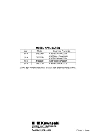
  • 1. MODEL APPLICATION Year Model Beginning Frame No. 2013 ZR800AD JKBZR800AADA00001 2013 ZR800BD JKBZRCB1□DDA00001 JKBZR800ABDA00001 2013 ZR800CD JKBZR800CCDA00001 2013 ZR800DD JKBZR800CDDA00001 □:This digit in the frame number changes from one machine to another. Part No.99924-1463-01 Printed in Japan
  • 3. This quick reference guide will assist you in locating a desired topic or pro- cedure. •Bend the pages back to match the black tab of the desired chapter num- ber with the black tab on the edge at each table of contents page. •Refer to the sectional table of contents for the exact pages to locate the spe- cific topic required. Quick Reference Guide General Information 1 j Periodic Maintenance 2 j Fuel System (DFI) 3 j Cooling System 4 j Engine Top End 5 j Clutch 6 j Engine Lubrication System 7 j Engine Removal/Installation 8 j Crankshaft/Transmission 9 j Wheels/Tires 10 j Final Drive 11 j Brakes 12 j Suspension 13 j Steering 14 j Frame 15 j Electrical System 16 j Appendix 17 j
  • 4. Z800 Z800 ABS Motorcycle Service Manual All rights reserved. No parts of this publication may be reproduced, stored in a retrieval system, or transmitted in any form or by any means, electronic mechanical photocopying, recording or otherwise, without the prior written permission of Quality Assurance Division/Motorcycle & Engine Company/Kawasaki Heavy Industries, Ltd., Japan. No liability can be accepted for any inaccuracies or omissions in this publication, although every possible care has been taken to make it as complete and accurate as possible. The right is reserved to make changes at any time without prior notice and without incurring an obligation to make such changes to products manufactured previously. See your Motorcycle dealer for the latest information on product improvements incorporated after this publication. All information contained in this publication is based on the latest product information available at the time of publication. Illustrations and photographs in this publication are intended for reference use only and may not depict actual model component parts. © 2012 Kawasaki Heavy Industries, Ltd. First Edition (3) : Sep. 7, 2012
  • 5. LIST OF ABBREVIATIONS A ampere(s) in. inch(s) ABDC after bottom dead center km/h kilometers per hour ABS antilock brake system L liter(s) AC alternating current LCD liquid crystal display Ah ampere hour LED light emitting diode ATDC after top dead center lb pound(s) BBDC before bottom dead center m meter(s) BDC bottom dead center min minute(s) BTDC before top dead center mmHg millimeters of mercury °C degree(s) Celsius mph miles per hour cmHg centimeters of mercury N newton(s) cu in cubic inch(s) oz ounce(s) DC direct current Pa pascal(s) DFI digital fuel injection PS horsepower DOHC double overhead camshaft psi pound(s) per square inch DOT department of transportation qt quart(s) ECU electronic control unit r revolution F farad(s) rpm revolution(s) per minute °F degree(s) Fahrenheit s second(s) ft foot, feet TDC top dead center g gram(s) TIR total indicator reading gal gallon(s) V volt(s) h hour(s) W watt(s) HP horsepower(s) Ω ohm(s) IC integrated circuit COUNTRY AND AREA CODES AU Australia WVTA (FULL) WVTA Model (Full Power) BR Brazil UK WVTA (FULL) WVTA Model (Left Side Traffic, Full Power) SEA-B2 Southeast Asia B2 WVTA (78.2) WVTA Model (78.2 kW Power)
  • 6. Foreword This manual is designed primarily for use by trained mechanics in a properly equipped shop. However, it contains enough detail and basic in- formation to make it useful to the owner who de- sires to perform his own basic maintenance and repair work. A basic knowledge of mechanics, the proper use of tools, and workshop proce- dures must be understood in order to carry out maintenance and repair satisfactorily. When- ever the owner has insufficient experience or doubts his ability to do the work, all adjust- ments, maintenance, and repair should be car- ried out only by qualified mechanics. In order to perform the work efficiently and to avoid costly mistakes, read the text, thor- oughly familiarize yourself with the procedures before starting work, and then do the work care- fully in a clean area. Whenever special tools or equipment are specified, do not use makeshift tools or equipment. Precision measurements can only be made if the proper instruments are used, and the use of substitute tools may ad- versely affect safe operation. For the duration of the warranty period, we recommend that all repairs and scheduled maintenance be performed in accordance with this service manual. Any owner maintenance or repair procedure not performed in accordance with this manual may void the warranty. To get the longest life out of your vehicle. •Follow the Periodic Maintenance Chart in the Service Manual. •Be alert for problems and non-scheduled maintenance. •Use proper tools and genuine Kawasaki Mo- torcycle parts. Special tools, gauges, and testers that are necessary when servicing Kawasaki motorcycles are introduced by the Service Manual. Genuine parts provided as spare parts are listed in the Parts Catalog. •Follow the procedures in this manual care- fully. Don’t take shortcuts. •Remember to keep complete records of main- tenance and repair with dates and any new parts installed. How to Use This Manual In this manual, the product is divided into its major systems and these systems make up the manual’s chapters. The Quick Reference Guide shows you all of the product’s system and assists in locating their chapters. Each chapter in turn has its own comprehensive Ta- ble of Contents. For example, if you want stick coil information, use the Quick Reference Guide to locate the Electrical System chapter. Then, use the Table of Contents on the first page of the chapter to find the Stick Coil section. Whenever you see symbols, heed their in- structions! Always follow safe operating and maintenance practices. DANGER DANGER indicates a hazardous situa- tion which, if not avoided, will result in death or serious injury. WARNING WARNING indicates a hazardous situa- tion which, if not avoided, could result in death or serious injury. NOTICE NOTICE is used to address practices not related to personal injury. This manual contains four more symbols which will help you distinguish different types of information. NOTE ○This note symbol indicates points of par- ticular interest for more efficient and con- venient operation. •Indicates a procedural step or work to be done. ○Indicates a procedural sub-step or how to do the work of the procedural step it follows. It also precedes the text of a NOTE. Indicates a conditional step or what action to take based on the results of the test or inspec- tion in the procedural step or sub-step it fol- lows. In most chapters an exploded view illustration of the system components follows the Table of Contents. In these illustrations you will find the instructions indicating which parts require spec- ified tightening torque, oil, grease or a locking agent during assembly.
  • 7. GENERAL INFORMATION 1-1 1 General Information Table of Contents Before Servicing ..................................................................................................................... 1-2 Model Identification................................................................................................................. 1-7 General Specifications............................................................................................................ 1-11 Unit Conversion Table ............................................................................................................ 1-14
  • 8. 1-2 GENERAL INFORMATION Before Servicing Before starting to perform an inspection service or carry out a disassembly and reassembly opera- tion on a motorcycle, read the precautions given below. To facilitate actual operations, notes, illustra- tions, photographs, cautions, and detailed descriptions have been included in each chapter wherever necessary. This section explains the items that require particular attention during the removal and reinstallation or disassembly and reassembly of general parts. Especially note the following. Battery Ground Before completing any service on the motorcycle, discon- nect the battery cables from the battery to prevent the en- gine from accidentally turning over. Disconnect the ground cable (–) first and then the positive (+). When completed with the service, first connect the positive (+) cable to the positive (+) terminal of the battery then the negative (–) ca- ble to the negative terminal. Edges of Parts Lift large or heavy parts wearing gloves to prevent injury from possible sharp edges on the parts. Solvent Use a high flash-point solvent when cleaning parts. High flash-point solvent should be used according to directions of the solvent manufacturer. Cleaning Vehicle before Disassembly Clean the vehicle thoroughly before disassembly. Dirt or other foreign materials entering into sealed areas during ve- hicle disassembly can cause excessive wear and decrease performance of the vehicle.
  • 9. GENERAL INFORMATION 1-3 Before Servicing Arrangement and Cleaning of Removed Parts Disassembled parts are easy to confuse. Arrange the parts according to the order the parts were disassembled and clean the parts in order prior to assembly. Storage of Removed Parts After all the parts including subassembly parts have been cleaned, store the parts in a clean area. Put a clean cloth or plastic sheet over the parts to protect from any foreign materials that may collect before re-assembly. Inspection Reuse of worn or damaged parts may lead to serious ac- cident. Visually inspect removed parts for corrosion, discol- oration, or other damage. Refer to the appropriate sections of this manual for service limits on individual parts. Replace the parts if any damage has been found or if the part is be- yond its service limit. Replacement Parts Replacement parts must be KAWASAKI genuine or recommended by KAWASAKI. Gaskets, O-rings, oil seals, grease seals, circlips, cotter pins or self-locking nuts must be replaced with new ones whenever disassembled. Assembly Order In most cases assembly order is the reverse of disassem- bly, however, if assembly order is provided in this Service Manual, follow the procedures given.
  • 10. 1-4 GENERAL INFORMATION Before Servicing Tightening Sequence Generally, when installing a part with several bolts, nuts, or screws, start them all in their holes and tighten them to a snug fit. Then tighten them according to the specified se- quence to prevent case warpage or deformation which can lead to malfunction. Conversely when loosening the bolts, nuts, or screws, first loosen all of them by about a quar- ter turn and then remove them. If the specified tightening sequence is not indicated, tighten the fasteners alternating diagonally. Tightening Torque Incorrect torque applied to a bolt, nut, or screw may lead to serious damage. Tighten fasteners to the specified torque using a good quality torque wrench. Force Use common sense during disassembly and assembly, excessive force can cause expensive or hard to repair dam- age. When necessary, remove screws that have a non -permanent locking agent applied using an impact driver. Use a plastic-faced mallet whenever tapping is necessary. Gasket, O-ring Hardening, shrinkage, or damage of both gaskets and O-rings after disassembly can reduce sealing performance. Remove old gaskets and clean the sealing surfaces thor- oughly so that no gasket material or other material remains. Install the new gaskets and replace the used O-rings when re-assembling. Liquid Gasket, Non-permanent Locking Agent For applications that require Liquid Gasket or a Non-Permanent Locking Agent, clean the surfaces so that no oil residue remains before applying liquid gasket or non-permanent locking agent. Do not apply them exces- sively. Excessive application can clog oil passages and cause serious damage.
  • 11. GENERAL INFORMATION 1-5 Before Servicing Press For items such as bearings or oil seals that must be pressed into place, apply small amount of oil to the con- tact area. Be sure to maintain proper alignment and use smooth movements when installing. Ball Bearing and Needle Bearing Do not remove pressed ball or needle unless removal is absolutely necessary. Replace with new ones whenever removed. Press bearings with the manufacturer and size marks facing out. Press the bearing into place by putting pressure on the correct bearing race as shown. Pressing the incorrect race can cause pressure between the inner and outer race and result in bearing damage. Oil Seal, Grease Seal Do not remove pressed oil or grease seals unless removal is necessary. Replace with new ones whenever removed. Press new oil seals with manufacture and size marks facing out. Make sure the seal is aligned properly when installing. Apply specified grease to the lip of seal before installing the seal. Circlips, Cotter Pins Replace the circlips or cotter pins that were removed with new ones. Take care not to open the clip excessively when installing to prevent deformation.
  • 12. 1-6 GENERAL INFORMATION Before Servicing Lubrication It is important to lubricate rotating or sliding parts during assembly to minimize wear during initial operation. Lubri- cation points are called out throughout this manual, apply the specific oil or grease as specified. Direction of Engine Rotation When rotating the crankshaft by hand, the free play amount of rotating direction will affect the adjustment. Ro- tate the crankshaft to positive direction (clockwise viewed from output side). Electrical Wires A two-color wire is identified first by the primary color and then the stripe color. Unless instructed otherwise, electrical wires must be connected to those of the same color. Instrument Use a meter that has enough accuracy for an accurate measurement. Read the manufacture’s instructions thor- oughly before using the meter. Incorrect values may lead to improper adjustments.
  • 13. GENERAL INFORMATION 1-7 Model Identification ZR800AD (Europe) Left Side View ZR800AD (Europe) Right Side View
  • 14. 1-8 GENERAL INFORMATION Model Identification ZR800BD (Europe) Left Side View ZR800BD (Europe) Right Side View
  • 15. GENERAL INFORMATION 1-9 Model Identification ZR800CD Left Side View ZR800CD Right Side View
  • 16. Thank you very much for your reading. Please Click Here. Then Get COMPLETE MANUAL. NO WAITING NOTE: If there is no response to click on the link above, please download the PDF document first and then click on it.
  • 17. 1-10 GENERAL INFORMATION Model Identification ZR800DD Left Side View ZR800DD Right Side View Frame Number Engine Number
  • 18. GENERAL INFORMATION 1-11 General Specifications Items ZR800AD/BD/CD/DD Dimensions Overall Length 2 100 mm (82.68 in.) Overall Width 800 mm (31.50 in.) Overall Height 1 050 mm (41.34 in.) Wheelbase 1 445 mm (56.89 in.) Road Clearance 150 mm (5.91 in.) Seat Height 834 mm (32.83 in.) Curb Mass: ZR800A 229 kg (504.9 lb) ZR800B 231 kg (509.4 lb) ZR800C 226 kg (498.3 lb) ZR800D 228 kg (502.7 lb) Front: ZR800A 116 kg (255.8 lb) ZR800B 117 kg (258.0 lb) ZR800C 114 kg (251.4 lb) ZR800D 115 kg (253.6 lb) Rear: ZR800A 113 kg (249.2 lb) ZR800B 114 kg (251.4 lb) ZR800C 112 kg (247.0 lb) ZR800D 113 kg (249.2 lb) Fuel Tank Capacity 17 L (4.5 US gal.) Performance Minimum Turning Radius 3.0 m (9.8 ft) Engine Type 4-stroke, DOHC, 4-cylinder Cooling System Liquid-cooled Bore and Stroke 71.0 × 50.9 mm (2.80 × 2.00 in.) Displacement 806 cm³ (49.18 cu in.) Compression Ratio 11.9 : 1 Maximum Horsepower: ZR800A/B 83.0 kW (113 PS) at 10 200 r/min (rpm) WVTA (78.2) 78.2 kW (106 PS) at 10 000 r/min (rpm) ZR800C/D 70.0 kW (95.2 PS) at 9 500 r/min (rpm) Maximum Torque: ZR800A/B 83.0 N·m (8.5 kgf·m, 61 ft·lb) at 8 000 r/min (rpm) WVTA (78.2) 80.5 N·m (8.2 kgf·m, 59 ft·lb) at 8 000 r/min (rpm) ZR800C/D 76.0 N·m (7.7 kgf·m, 56 ft·lb) at 8 000 r/min (rpm) Fuel System FI (Fuel Injection) MIKUNI 34 EHDW × 4 Starting System Electric starter Ignition System Battery and coil (transistorized) Timing Advance Electronically advanced (digital igniter) Ignition Timing From 10° BTDC at 1 100 r/min (rpm) to 37° BTDC at 5 000 r/min (rpm)
  • 19. 1-12 GENERAL INFORMATION General Specifications Items ZR800AD/BD/CD/DD Spark Plug NGK CR9EK, ND U27ETR Cylinder Numbering Method Left to right, 1-2-3-4 Firing Order 1-2-4-3 Valve Timing: Intake: Open 38° BTDC Close 66° ABDC Duration 284° Exhaust: Open 51° BBDC Close 25° ATDC Duration 256° Lubrication System Forced lubrication (wet sump) Engine Oil: Type API SG, SH, SJ, SL or SM with JASO MA, MA1 or MA2 Viscosity SAE 10W-40 Capacity 3.8 L (4.0 US qt) Drive Train Primary Reduction System: Type Gear Reduction Ratio 1.714 (84/49) Clutch Type Wet multi disc Transmission: Type 6-speed, constant mesh, return shift Gear Ratios: 1st 2.571 (36/14) 2nd 1.941 (33/17) 3rd 1.556 (28/18) 4th 1.333 (28/21) 5th 1.200 (24/20) 6th 1.095 (23/21) Final Drive System: Type Chain drive Reduction Ratio 3.000 (45/15) Overall Drive Ratio 5.633 at Top gear Frame Type Tubular, diamond Caster (Rake Angle) 24° Trail 98 mm (3.86 in.) Front Tire: Type Tubeless Size 120/70ZR17 M/C (58W) Rim Size J17M/C × MT3.50
  • 20. GENERAL INFORMATION 1-13 General Specifications Items ZR800AD/BD/CD/DD Rear Tire: Type Tubeless Size 180/55ZR17 M/C (73W) Rim Size J17M/C × MT5.50 Front Suspension: Type Telescopic fork Wheel Travel 120 mm (4.72 in.) Rear Suspension: Type Swingarm (uni-trak) Wheel Travel 137 mm (5.39 in.) Brake Type: Front Dual discs Rear Single disc Electrical Equipment Battery 12 V 8 Ah Headlight: Type Semi-sealed beam Bulb: High Beam 12 V 55 W × 2 Low Beam 12 V 55 W Tail/Brake Light LED Alternator: Type Three-phase AC Rated Output 30.1 A/14.0 V at 5 000 r/min (rpm) Specifications are subject to change without notice, and may not apply to every country.
  • 21. 1-14 GENERAL INFORMATION Unit Conversion Table Prefixes for Units: Prefix Symbol Power mega M × 1 000 000 kilo k × 1 000 centi c × 0.01 milli m × 0.001 micro µ × 0.000001 Units of Mass: kg × 2.205 = lb g × 0.03527 = oz Units of Volume: L × 0.2642 = gal (US) L × 0.2200 = gal (IMP) L × 1.057 = qt (US) L × 0.8799 = qt (IMP) L × 2.113 = pint (US) L × 1.816 = pint (IMP) mL × 0.03381 = oz (US) mL × 0.02816 = oz (IMP) mL × 0.06102 = cu in. Units of Force: N × 0.1020 = kg N × 0.2248 = lb kg × 9.807 = N kg × 2.205 = lb Units of Length: km × 0.6214 = mile m × 3.281 = ft mm × 0.03937 = in. Units of Torque: N·m × 0.1020 = kgf·m N·m × 0.7376 = ft·lb N·m × 8.851 = in·lb kgf·m × 9.807 = N·m kgf·m × 7.233 = ft·lb kgf·m × 86.80 = in·lb Units of Pressure: kPa × 0.01020 = kgf/cm² kPa × 0.1450 = psi kPa × 0.7501 = cmHg kgf/cm² × 98.07 = kPa kgf/cm² × 14.22 = psi cmHg × 1.333 = kPa Units of Speed: km/h × 0.6214 = mph Units of Power: kW × 1.360 = PS kW × 1.341 = HP PS × 0.7355 = kW PS × 0.9863 = HP Units of Temperature:
  • 22. PERIODIC MAINTENANCE 2-1 2 Periodic Maintenance Table of Contents Periodic Maintenance Chart ................................................................................................... 2-3 Torque and Locking Agent...................................................................................................... 2-5 Specifications ......................................................................................................................... 2-11 Special Tools .......................................................................................................................... 2-13 Periodic Maintenance Procedures.......................................................................................... 2-14 Fuel System (DFI)................................................................................................................ 2-14 Air Cleaner Element Cleaning........................................................................................... 2-14 Air Cleaner Element Replacement.................................................................................... 2-14 Idle Speed Inspection ....................................................................................................... 2-16 Idle Speed Adjustment...................................................................................................... 2-16 Throttle Control System Inspection................................................................................... 2-16 Engine Vacuum Synchronization Inspection..................................................................... 2-17 Fuel System...................................................................................................................... 2-20 Fuel Hose Replacement ................................................................................................... 2-22 Cooling System.................................................................................................................... 2-25 Coolant Level Inspection................................................................................................... 2-25 Cooling System................................................................................................................. 2-25 Coolant Change................................................................................................................ 2-25 Water Hose and O-ring Replacement............................................................................... 2-28 Engine Top End ................................................................................................................... 2-28 Valve Clearance Inspection .............................................................................................. 2-28 Valve Clearance Adjustment............................................................................................. 2-30 Air Suction System Damage Inspection............................................................................ 2-33 Clutch................................................................................................................................... 2-33 Clutch Operation Inspection.............................................................................................. 2-33 Engine Lubrication System.................................................................................................. 2-34 Engine Oil Change............................................................................................................ 2-34 Oil Filter Replacement ...................................................................................................... 2-35 Wheels/Tires........................................................................................................................ 2-36 Air Pressure Inspection..................................................................................................... 2-36 Wheels and Tires .............................................................................................................. 2-36 Wheel Bearing Damage Inspection .................................................................................. 2-37 Final Drive............................................................................................................................ 2-38 Drive Chain Lubrication Condition Inspection................................................................... 2-38 Drive Chain Slack Inspection............................................................................................ 2-38 Drive Chain Slack Adjustment .......................................................................................... 2-39 Wheel Alignment Inspection ............................................................................................. 2-40 Drive Chain Wear Inspection ............................................................................................ 2-40 Chain Guide Wear Inspection........................................................................................... 2-41 Brakes.................................................................................................................................. 2-42 Brake System.................................................................................................................... 2-42 Brake Fluid Level Inspection............................................................................................. 2-43 Brake Fluid Change .......................................................................................................... 2-44 Brake Hose and Pipe Replacement.................................................................................. 2-46 Master Cylinder Rubber Parts Replacement .................................................................... 2-47 Caliper Rubber Parts Replacement .................................................................................. 2-48 Brake Pad Wear Inspection .............................................................................................. 2-52 Brake Light Switch Operation Inspection.......................................................................... 2-52 Suspension.......................................................................................................................... 2-53 Suspension System .......................................................................................................... 2-53