Here are a few key points about how to use this service manual:
- The manual contains removal, installation, inspection and adjustment procedures as well as troubleshooting information.
- Important warnings and cautions are highlighted in bold text to draw attention.
- Standard values indicate the acceptable range for inspections and adjustments. Limit values are the maximum or minimum allowed.
- Metric and imperial units are both used. Torque specifications list the acceptable range as well as the standard value.
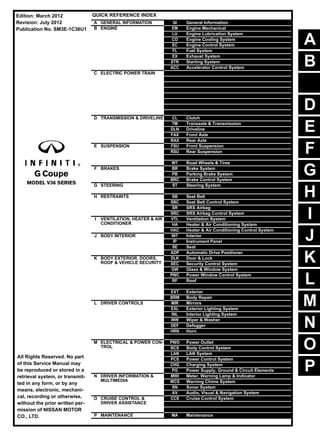
- A quick reference index is provided on the first page for easy navigation to different sections.
- The contents page lists the subsections within each section.
- Page numbers indicate the section and page, such as "BR
Comprehensive program for Agricultural Finance, the Automotive Sector, and Empowerment . We will define the full scope and provide a detailed two-week plan for identifying strategic partners in each area within Limpopo, including target areas.:
1. Agricultural : Supporting Primary and Secondary Agriculture
• Scope: Provide support solutions to enhance agricultural productivity and sustainability.
• Target Areas: Polokwane, Tzaneen, Thohoyandou, Makhado, and Giyani.
2. Automotive Sector: Partnerships with Mechanics and Panel Beater Shops
• Scope: Develop collaborations with automotive service providers to improve service quality and business operations.
• Target Areas: Polokwane, Lephalale, Mokopane, Phalaborwa, and Bela-Bela.
3. Empowerment : Focusing on Women Empowerment
• Scope: Provide business support support and training to women-owned businesses, promoting economic inclusion.
• Target Areas: Polokwane, Thohoyandou, Musina, Burgersfort, and Louis Trichardt.
We will also prioritize Industrial Economic Zone areas and their priorities.
Sign up on https://profilesmes.online/welcome/
To be eligible:
1. You must have a registered business and operate in Limpopo
2. Generate revenue
3. Sectors : Agriculture ( primary and secondary) and Automative
Women and Youth are encouraged to apply even if you don't fall in those sectors.
5 Warning Signs Your BMW's Intelligent Battery Sensor Needs AttentionBertini's German Motors
IBS monitors and manages your BMW’s battery performance. If it malfunctions, you will have to deal with an array of electrical issues in your vehicle. Recognize warning signs like dimming headlights, frequent battery replacements, and electrical malfunctions to address potential IBS issues promptly.
Why Is Your BMW X3 Hood Not Responding To Release CommandsDart Auto
Experiencing difficulty opening your BMW X3's hood? This guide explores potential issues like mechanical obstruction, hood release mechanism failure, electrical problems, and emergency release malfunctions. Troubleshooting tips include basic checks, clearing obstructions, applying pressure, and using the emergency release.
"Trans Failsafe Prog" on your BMW X5 indicates potential transmission issues requiring immediate action. This safety feature activates in response to abnormalities like low fluid levels, leaks, faulty sensors, electrical or mechanical failures, and overheating.
In this presentation, we have discussed a very important feature of BMW X5 cars… the Comfort Access. Things that can significantly limit its functionality. And things that you can try to restore the functionality of such a convenient feature of your vehicle.
𝘼𝙣𝙩𝙞𝙦𝙪𝙚 𝙋𝙡𝙖𝙨𝙩𝙞𝙘 𝙏𝙧𝙖𝙙𝙚𝙧𝙨 𝙞𝙨 𝙫𝙚𝙧𝙮 𝙛𝙖𝙢𝙤𝙪𝙨 𝙛𝙤𝙧 𝙢𝙖𝙣𝙪𝙛𝙖𝙘𝙩𝙪𝙧𝙞𝙣𝙜 𝙩𝙝𝙚𝙞𝙧 𝙥𝙧𝙤𝙙𝙪𝙘𝙩𝙨. 𝙒𝙚 𝙝𝙖𝙫𝙚 𝙖𝙡𝙡 𝙩𝙝𝙚 𝙥𝙡𝙖𝙨𝙩𝙞𝙘 𝙜𝙧𝙖𝙣𝙪𝙡𝙚𝙨 𝙪𝙨𝙚𝙙 𝙞𝙣 𝙖𝙪𝙩𝙤𝙢𝙤𝙩𝙞𝙫𝙚 𝙖𝙣𝙙 𝙖𝙪𝙩𝙤 𝙥𝙖𝙧𝙩𝙨 𝙖𝙣𝙙 𝙖𝙡𝙡 𝙩𝙝𝙚 𝙛𝙖𝙢𝙤𝙪𝙨 𝙘𝙤𝙢𝙥𝙖𝙣𝙞𝙚𝙨 𝙗𝙪𝙮 𝙩𝙝𝙚 𝙜𝙧𝙖𝙣𝙪𝙡𝙚𝙨 𝙛𝙧𝙤𝙢 𝙪𝙨.
Over the 10 years, we have gained a strong foothold in the market due to our range's high quality, competitive prices, and time-lined delivery schedules.
Things to remember while upgrading the brakes of your carjennifermiller8137
Upgrading the brakes of your car? Keep these things in mind before doing so. Additionally, start using an OBD 2 GPS tracker so that you never miss a vehicle maintenance appointment. On top of this, a car GPS tracker will also let you master good driving habits that will let you increase the operational life of your car’s brakes.
Ever been troubled by the blinking sign and didn’t know what to do?
Here’s a handy guide to dashboard symbols so that you’ll never be confused again!
Save them for later and save the trouble!
Fleet management these days is next to impossible without connected vehicle solutions. Why? Well, fleet trackers and accompanying connected vehicle management solutions tend to offer quite a few hard-to-ignore benefits to fleet managers and businesses alike. Let’s check them out!
What Does the PARKTRONIC Inoperative, See Owner's Manual Message Mean for You...Autohaus Service and Sales
Learn what "PARKTRONIC Inoperative, See Owner's Manual" means for your Mercedes-Benz. This message indicates a malfunction in the parking assistance system, potentially due to sensor issues or electrical faults. Prompt attention is crucial to ensure safety and functionality. Follow steps outlined for diagnosis and repair in the owner's manual.
Core technology of Hyundai Motor Group's EV platform 'E-GMP'Hyundai Motor Group
What’s the force behind Hyundai Motor Group's EV performance and quality?
Maximized driving performance and quick charging time through high-density battery pack and fast charging technology and applicable to various vehicle types!
Discover more about Hyundai Motor Group’s EV platform ‘E-GMP’!
What Exactly Is The Common Rail Direct Injection System & How Does It WorkMotor Cars International
Learn about Common Rail Direct Injection (CRDi) - the revolutionary technology that has made diesel engines more efficient. Explore its workings, advantages like enhanced fuel efficiency and increased power output, along with drawbacks such as complexity and higher initial cost. Compare CRDi with traditional diesel engines and discover why it's the preferred choice for modern engines.
What Exactly Is The Common Rail Direct Injection System & How Does It Work
2013 Infiniti G37 Coupe Service Repair Manual.pdf
1. A
B
D
E
F
G
H
I
J
K
L
M
N
P
O
C
QUICK REFERENCE INDEX
A GENERAL INFORMATION GI General Information
B ENGINE EM Engine Mechanical
LU Engine Lubrication System
CO Engine Cooling System
EC Engine Control System
FL Fuel System
EX Exhaust System
STR Starting System
ACC Accelerator Control System
C ELECTRIC POWER TRAIN HBC Hybrid Control System
HBB Hybrid Battery System
HBR Hybrid Brake System
EVC EV Control System
TMS Traction Motor System
EVB EV Battery System
VC Vehicle Charging System
HCO High Voltage Cooling System
D TRANSMISSION & DRIVELINE CL Clutch
TM Transaxle & Transmission
DLN Driveline
FAX Front Axle
RAX Rear Axle
E SUSPENSION FSU Front Suspension
RSU Rear Suspension
SCS Suspension Control System
WT Road Wheels & Tires
F BRAKES BR Brake System
PB Parking Brake System
BRC Brake Control System
G STEERING ST Steering System
H RESTRAINTS SB Seat Belt
SBC Seat Belt Control System
SR SRS Airbag
SRC SRS Airbag Control System
I VENTILATION, HEATER & AIR
CONDITIONER
VTL Ventilation System
HA Heater & Air Conditioning System
HAC Heater & Air Conditioning Control System
J BODY INTERIOR INT Interior
IP Instrument Panel
SE Seat
ADP Automatic Drive Positioner
K BODY EXTERIOR, DOORS,
ROOF & VEHICLE SECURITY
DLK Door & Lock
SEC Security Control System
GW Glass & Window System
PWC Power Window Control System
RF Roof
HD Hood
EXT Exterior
BRM Body Repair
L DRIVER CONTROLS MIR Mirrors
EXL Exterior Lighting System
INL Interior Lighting System
WW Wiper & Washer
DEF Defogger
HRN Horn
VSP Approaching Vehicle Sound for Pedestrians (VSP)
M ELECTRICAL & POWER CON-
TROL
PWO Power Outlet
BCS Body Control System
LAN LAN System
PCS Power Control System
CHG Charging System
PG Power Supply, Ground & Circuit Elements
N DRIVER INFORMATION &
MULTIMEDIA
MWI Meter, Warning Lamp & Indicator
WCS Warning Chime System
SN Sonar System
AV Audio, Visual & Navigation System
O CRUISE CONTROL &
DRIVER ASSISTANCE
CCS Cruise Control System
DAS Driver Assistance System
DMS Drive Mode System
P MAINTENANCE MA Maintenance
All Rights Reserved. No part
of this Service Manual may
be reproduced or stored in a
retrieval system, or transmit-
ted in any form, or by any
means, electronic, mechani-
cal, recording or otherwise,
without the prior written per-
mission of NISSAN MOTOR
CO., LTD.
Edition: March 2012
Revision: July 2012
Publication No. SM3E-1C36U1
2. FOREWORD
This manual contains maintenance and repair procedure for the 2013
INFINITI G Coupe.
In order to assure your safety and the efficient functioning of the vehicle,
this manual should be read thoroughly. It is especially important that the
PRECAUTIONS in the GI section be completely understood before starting
any repair task.
All information in this manual is based on the latest product information
at the time of publication. The right is reserved to make changes in specifi-
cations and methods at any time without notice.
IMPORTANT SAFETY NOTICE
The proper performance of service is essential for both the safety of
the technician and the efficient functioning of the vehicle.
The service methods in this Service Manual are described in such a
manner that the service may be performed safely and accurately.
Service varies with the procedures used, the skills of the technician
and the tools and parts available. Accordingly, anyone using service
procedures, tools or parts which are not specifically recommended
by NISSAN must first be completely satisfied that neither personal
safety nor the vehicle’s safety will be jeopardized by the service
method selected.
3. QUICK REFERENCE CHART G COUPE
QUICK REFERENCE CHART G COUPE PFP:00000
ENGINE TUNE-UP DATA (VQ37VHR) ELS0003W
Engine model VQ37VHR
Firing order 1-2-3-4-5-6
Idle speed
A/T (In “P or N” position)
M/T (In Neutral position)
rpm
650 ± 50
Ignition timing
(BTDC at idle speed)
10° ± 5°
Tensions of drive belt
Belt tension is not necessary, as it is automatically
adjusted by drive belt auto-tensioner.
Radiater cap relief pressure kPa (kg/cm2
, psi)
Standard 122.3 - 151.7 (1.2 - 1.5, 18 - 22)
Limit 107 (1.1, 16)
Cooling system leakage testing pressure kPa (kg/cm2
, psi)
157 (1.6, 23)
Compression pressure kPa (kg/cm2, psi)/200 rpm
Standard 1,667 - 2,354 (17 - 24, 242 - 341)
Minimum 1,226 (12.5, 178)
Differential limit between cylinders 98 (1.0, 14)
Spark plug
(Iridium-tipped type)
Make DENSO
Standard type FXE24HR11
Gap (Nominal) mm (in) 1.1 (0.043)
2013
4. QUICK REFERENCE CHART G COUPE
FRONT WHEEL ALIGNMENT ELS0003X
Measure value under unladen* conditions.
*: Fuel, engine coolant and lubricant are full. Spare tire, jack, hand tools and mats are in designated positions.
REAR WHEEL ALIGNMENT ELS0003Y
Measure value under unladen* conditions.
*: Fuel, engine coolant and lubricant are full. Spare tire, jack, hand tools and mats are in designated positions.
Applied model 2WD AWD
Camber
Degree minute (Decimal degree)
Minimum –1° 10′ (–1.16°)
Nominal –0° 25′ (–0.42°)
Maximum 0° 20′ (0.33°)
Left and right difference 0° 33′ (0.55°) or less
Caster
Degree minute (Decimal degree)
Minimum 4° 05′ (4.08°) 3° 30′ (3.50°)
Nominal 4° 50′ (4.83°) 4° 15′ (4.25°)
Maximum 5° 35′ (5.58°) 5° 00′ (5.00°)
Left and right difference 0° 39′ (0.65°) or less
Kingpin inclination
Degree minute (Decimal degree)
Minimum 6° 40′ (6.67°)
Nominal 7° 25′ (7.42°)
Maximum 8° 10′ (8.16°)
Toe-in
Total toe-in
Distance
Minimum Out 1 mm (Out 0.03 in)
Nominal In 1 mm (In 0.04 in)
Maximum In 3 mm (In 0.11 in)
Total toe-angle
Degree minute (Decimal degree)
Minimum Out 0° 04′ 48″ (Out 0.08°)
Nominal In 0° 04′ 48″ (In 0.08°)
Maximum In 0° 15′ 00″ (In 0.25°)
Item Standard
Camber
Degree minute (Decimal degree)
Minimum –1° 45′ (–1.75°)
Nominal –1° 15′ (–1.25°)
Maximum –0° 45′ (–0.75°)
Toe-in
Total toe-in
Distance
Minimum 0 mm (0 in)
Nominal In 2.8 mm (In 0.110 in)
Maximum In 5.6 mm (In 0.220 in)
Total toe-angle
Degree minute (Decimal degree)
Minimum 0° 00′ (0.00°)
Nominal In 0° 14′ 24″ (In 0.24°)
Maximum In 0° 28′ 12″ (In 0.47°)
2013
5. QUICK REFERENCE CHART G COUPE
BRAKE PEDAL
Unit: mm (in)
FRONT DISC BRAKE
1 Piston Type
Unit: mm (in)
4 Piston Type
Unit: mm (in)
REAR DISC BRAKE
1 Piston Type
Unit: mm (in)
2 Piston Type
Unit: mm (in)
Brake pedal height (H1) 171.5 - 181.5 (6.75 - 7.15)
Depressed brake pedal height (H2)
[Depressing 490 N (50 kg, 110 lb) while turning the engine ON]
124.0 (4.88) or more
Item Limit
Brake pad Wear thickness 2.0 (0.079)
Disc rotor
Wear thickness 30.0 (1.181)
Thickness variation (measured at 8 positions) 0.015 (0.0006)
Runout (with it attached to the vehicle) 0.035 (0.0014)
Item Limit
Brake pad Wear thickness 2.0 (0.079)
Disc rotor
Wear thickness 30.0 (1.181)
Thickness variation (measured at 8 positions) 0.015 (0.0006)
Runout (with it attached to the vehicle) 0.035 (0.0014)
Item Limit
Brake pad Wear thickness 2.0 (0.079)
Disc rotor
Wear thickness 15.0 (0.591)
Thickness variation (measured at 8 positions) 0.015 (0.0006)
Runout (with it attached to the vehicle) 0.055 (0.0022)
Item Limit
Brake pad Wear thickness 2.0 (0.079)
Disc rotor
Wear thickness 18.0 (0.709)
Thickness variation (measured at 8 positions) 0.015 (0.0006)
Runout (with it attached to the vehicle) 0.055 (0.0022)
2013
6. QUICK REFERENCE CHART G COUPE
REFILL CAPACITIES ELS00040
UNIT Liter US measure
Fuel tank 75.6 20 gal
Engine coolant capacity
[with reservoir tank (“MAX” level)]
A/T models 8.5 9 qt
M/T models 8.6 9-1/8 qt
Engine oil
Drain and refill
With oil filter change 4.9 5-1/8 qt
Without oil filter change 4.6 4-7/8 qt
Dry engine (Overhaul) 5.7 6 qt
Transmission
A/T 9.2 9-3/4 qt
M/T 2.83 6 pt
Transfer 1.0 2-1/8 pt
Final drive
Front 0.65 1-3/8 pt
Rear 1.4 3 pt
Power steering system 1.0 1-1/8 qt
Air conditioning system
Compressor oil 0.15 5.07 fl oz
Refrigerant 0.55 kg 1.21 lb
2013
7. GI-1
GENERAL INFORMATION
C
D
E
F
G
H
I
J
K
L
M
B
GI
SECTION GI
N
O
P
CONTENTS
GENERAL INFORMATION
HOW TO USE THIS MANUAL ..................
.... 3
HOW TO USE THIS MANUAL .......................
..... 3
Description ..........................................................
......3
Terms ..................................................................
......3
Units ....................................................................
......3
Contents ..............................................................
......3
Relation between Illustrations and Descriptions .
......4
Components ........................................................
......4
HOW TO FOLLOW TROUBLE DIAGNOSES..... 6
Description ..........................................................
......6
How to Follow Test Groups in Trouble Diagnosis......6
Key to Symbols Signifying Measurements or Pro-
cedures ...............................................................
......7
HOW TO READ WIRING DIAGRAMS ...........
..... 9
Connector Symbols .............................................
......9
Sample/Wiring Diagram -Example- .....................
....10
Connector Information .........................................
....12
ABBREVIATIONS ..........................................
....14
Abbreviation List ..................................................
....14
TIGHTENING TORQUE OF STANDARD
BOLTS ............................................................
....19
Description ..........................................................
....19
Tightening Torque Table (New Standard Includ-
ed) .......................................................................
....19
RECOMMENDED CHEMICAL PRODUCTS
AND SEALANTS ............................................
....22
Recommended Chemical Products and Sealants
....22
VEHICLE INFORMATION .........................
...23
IDENTIFICATION INFORMATION .................
....23
Model Variation ...................................................
....23
Information About Identification or Model Code ..
....23
Dimensions .........................................................
....26
Wheels & Tires ....................................................
....27
PRECAUTION ...........................................
...28
PRECAUTIONS .................................................28
Description ...........................................................
....28
Precaution for Supplemental Restraint System
(SRS) "AIR BAG" and "SEAT BELT PRE-TEN-
SIONER" .............................................................
....28
Precaution for Battery Service .............................
....28
Precaution for Procedure without Cowl Top Cover
....28
Precautions For Xenon Headlamp Service .........
....29
Cautions in Removing Battery Terminal and AV
Control Unit (Models with AV Control Unit) .........
....29
General Precautions ............................................
....29
Three Way Catalyst .............................................
....31
Multiport Fuel Injection System or Engine Control
System .................................................................
....31
Hoses ..................................................................
....31
Engine Oils ..........................................................
....32
Air Conditioning ...................................................
....32
Fuel ......................................................................
....33
LIFTING POINT .................................................34
Commercial Service Tools ...................................
....34
Garage Jack and Safety Stand and 2-Pole Lift ...
....34
Board-On Lift .......................................................
....35
TOW TRUCK TOWING .....................................36
Tow Truck Towing ...............................................
....36
Vehicle Recovery (Freeing a Stuck Vehicle) .......
....37
BASIC INSPECTION ................................
...39
SERVICE INFORMATION FOR ELECTRICAL
INCIDENT ..........................................................39
Work Flow ............................................................
....39
Control Units and Electrical Parts ........................
....39
How to Check Terminal .......................................
....40
Intermittent Incident .............................................
....43
Circuit Inspection .................................................
....46
CONSULT/GST CHECKING SYSTEM .............51
Description ...........................................................
....51
Revision: 2012 July 2013 G Coupe
8. GI-2
CONSULT Function and System Application*1 ...
... 51
CONSULT/GST Data Link Connector (DLC) Cir-
cuit .......................................................................
... 52
Wiring Diagram - CONSULT/GST CHECKING
SYSTEM - ............................................................
... 53
INSPECTION AND ADJUSTMENT ................
... 55
ADDITIONAL SERVICE WHEN REMOVING BAT-
TERY NEGATIVE TERMINAL ...............................
... 55
ADDITIONAL SERVICE WHEN REMOVING
BATTERY NEGATIVE TERMINAL : Required
Procedure After Battery Disconnection ................
... 55
Revision: 2012 July 2013 G Coupe
9. HOW TO USE THIS MANUAL
GI-3
< HOW TO USE THIS MANUAL >
C
D
E
F
G
H
I
J
K
L
M
B
GI
N
O
P
HOW TO USE THIS MANUAL
HOW TO USE THIS MANUAL
Description INFOID:0000000008162668
This volume explains “Removal, Disassembly, Installation, Inspection and Adjustment” and “Trouble Diag-
noses”.
Terms INFOID:0000000008162669
• The captions WARNING and CAUTION warn you of steps that must be followed to prevent personal injury
and/or damage to some part of the vehicle.
WARNING indicates the possibility of personal injury if instructions are not followed.
CAUTION indicates the possibility of component damage if instructions are not followed.
BOLD TYPED STATEMENTS except WARNING and CAUTION give you helpful information.
Standard value: Tolerance at inspection and adjustment.
Limit value: The maximum or minimum limit value that should not be exceeded at inspection and adjust-
ment.
Units INFOID:0000000008162670
• The UNITS given in this manual are primarily expressed as the SI UNIT (International System of Unit), and
alternatively expressed in the metric system and in the yard/pound system.
Also with regard to tightening torque of bolts and nuts, there are descriptions both about range and about the
standard tightening torque.
“Example”
Range
Standard
Contents INFOID:0000000008162671
• A QUICK REFERENCE INDEX, a black tab (e.g. ) is provided on the first page. You can quickly find the
first page of each section by matching it to the section's black tab.
• THE CONTENTS are listed on the first page of each section.
• THE TITLE is indicated on the upper portion of each page and shows the part or system.
• THE PAGE NUMBER of each section consists of two or three letters which designate the particular section
and a number (e.g. “BR-5”).
• THE SMALL ILLUSTRATIONS show the important steps such as inspection, use of special tools, knacks of
work and hidden or tricky steps which are not shown in the previous large illustrations.
Assembly, inspection and adjustment procedures for the complicated units such as the automatic transaxle
or transmission, etc. are presented in a step-by-step format where necessary.
Outer Socket Lock Nut : 59 - 78 N·m (6.0 - 8.0 kg-m, 43 - 58 ft-lb)
Drive Shaft Installation Bolt : 44.3 N·m (4.5 kg-m, 33 ft-lb)
Revision: 2012 July 2013 G Coupe
10. GI-4
< HOW TO USE THIS MANUAL >
HOW TO USE THIS MANUAL
Relation between Illustrations and Descriptions INFOID:0000000008162672
The following sample explains the relationship between the part description in an illustration, the part name in
the text and the service procedures.
Components INFOID:0000000008162673
• THE LARGE ILLUSTRATIONS are exploded views (see the following) and contain tightening torques, lubri-
cation points, section number of the PARTS CATALOG (e.g. SEC. 440) and other information necessary to
perform repairs.
The illustrations should be used in reference to service matters only. When ordering parts, refer to the appro-
priate PARTS CATALOG.
Components shown in an illustration may be identified by a circled number. When this style of illustration is
used, the text description of the components will follow the illustration.
SAIA0519E
Revision: 2012 July 2013 G Coupe
11. HOW TO USE THIS MANUAL
GI-5
< HOW TO USE THIS MANUAL >
C
D
E
F
G
H
I
J
K
L
M
B
GI
N
O
P
SYMBOLS
1. Union bolt 2. Copper washer 3. Brake hose
4. Cap 5. Bleed valve 6. Sliding pin bolt
7. Piston seal 8. Piston 9. Piston boot
10. Cylinder body 11. Sliding pin 12. Torque member mounting bolt
13. Washer 14. Sliding pin boot 15. Bushing
16. Torque member 17. Inner shim cover 18. Inner shim
19. Inner pad 20. Pad retainer 21. Pad wear sensor
22. Outer pad 23. Outer shim 24. Outer shim cover
1: PBC (Poly Butyl Cuprysil) grease
or silicone-based grease
2: Rubber grease : Brake fluid
Refer to GI section for additional symbol definitions.
SFIA2959E
SAIA0749E
Revision: 2012 July 2013 G Coupe
12. GI-6
< HOW TO USE THIS MANUAL >
HOW TO FOLLOW TROUBLE DIAGNOSES
HOW TO FOLLOW TROUBLE DIAGNOSES
Description INFOID:0000000008162674
NOTICE:
Trouble diagnoses indicate work procedures required to diagnose problems effectively. Observe the following
instructions before diagnosing.
• Before performing trouble diagnoses, read the “Work Flow” in each section.
• After repairs, re-check that the problem has been completely eliminated.
• Refer to Component Parts and Harness Connector Location for the Systems described in each section for
identification/location of components and harness connectors.
• When checking circuit continuity, ignition switch should be OFF.
• Refer to the Circuit Diagram for quick pinpoint check.
If you need to check circuit continuity between harness connectors in more detail, such as when a sub-har-
ness is used, refer to Wiring Diagram in each individual section and Harness Layout in PG section for identi-
fication of harness connectors.
• Before checking voltage at connectors, check battery voltage.
• After accomplishing the Diagnosis Procedures and Electrical Components Inspection, check that all harness
connectors are reconnected as they were.
How to Follow Test Groups in Trouble Diagnosis INFOID:0000000008162675
1. Test group number and test group title
• Test group number and test group title are shown in the upper portion of each test group.
2. Work and diagnosis procedure
• Start to diagnose a problem using procedures indicated in enclosed test groups.
3. Questions and results
• Questions and required results are indicated in test group.
4. Action
• Next action for each test group is indicated based on result of each question.
JPAIA0021GB
Revision: 2012 July 2013 G Coupe
13. HOW TO FOLLOW TROUBLE DIAGNOSES
GI-7
< HOW TO USE THIS MANUAL >
C
D
E
F
G
H
I
J
K
L
M
B
GI
N
O
P
Key to Symbols Signifying Measurements or Procedures INFOID:0000000008162676
JPAIA0982GB
Revision: 2012 July 2013 G Coupe
14. GI-8
< HOW TO USE THIS MANUAL >
HOW TO FOLLOW TROUBLE DIAGNOSES
JSAIA1461GB
Revision: 2012 July 2013 G Coupe
15. HOW TO READ WIRING DIAGRAMS
GI-9
< HOW TO USE THIS MANUAL >
C
D
E
F
G
H
I
J
K
L
M
B
GI
N
O
P
HOW TO READ WIRING DIAGRAMS
Connector Symbols INFOID:0000000008162677
Most of connector symbols in wiring diagrams are shown from the terminal side.
• Connector symbols shown from the terminal side are enclosed by
a single line and followed by the direction mark.
• Connector symbols shown from the harness side are enclosed by
a double line and followed by the direction mark.
• Certain systems and components, especially those related to
OBD, may use a new style slide-locking type harness connector.
For description and how to disconnect, refer to PG section,
“Description”, “HARNESS CONNECTOR”.
• Male and female terminals
Connector guides for male terminals are shown in black and
female terminals in white in wiring diagrams.
SAIA0257E
SGI363
Revision: 2012 July 2013 G Coupe
16. GI-10
< HOW TO USE THIS MANUAL >
HOW TO READ WIRING DIAGRAMS
Sample/Wiring Diagram -Example- INFOID:0000000008162678
Each section includes wiring diagrams.
Description
JCAWA0150GB
Number Item Description
1 Power supply • This means the power supply of fusible link or fuse.
2 Fuse • “/” means the fuse.
3
Current rating of fusible
link/fuse
• This means the current rating of the fusible link or fuse.
4
Number of fusible link/
fuse
• This means the number of fusible link or fuse location.
5 Fusible link • “X” means the fusible link.
6 Connector number
• Alphabetic characters show to which harness the connector is placed.
• Numeric characters show the identification number of connectors.
7 Switch
• This shows that continuity exists between terminals 1 and 2 when the switch is in the A posi-
tion. Continuity exists between terminals 1 and 3 when the switch is in the B position.
8 Circuit (Wiring) • This means the wiring.
Revision: 2012 July 2013 G Coupe
17. HOW TO READ WIRING DIAGRAMS
GI-11
< HOW TO USE THIS MANUAL >
C
D
E
F
G
H
I
J
K
L
M
B
GI
N
O
P
SWITCH POSITIONS
Switches are shown in wiring diagrams as if the vehicle is in the “normal” condition.
A vehicle is in the “normal” condition when:
• ignition switch is “OFF”
• doors, hood and trunk lid/back door are closed
• pedals are not depressed
• parking brake is released
MULTIPLE SWITCH
The continuity of multiple switch is described in two ways as shown below.
• The switch chart is used in schematic diagrams.
9 Shielded line • The line enclosed by broken line circle shows shield wire.
10 Connectors • This means that a transmission line bypasses two connectors or more.
11 Option abbreviation • This means the vehicle specifications which layouts the circuit between “ ”.
12 Relay • This shows an internal representation of the relay.
13 Optional splice • The open circle shows that the splice is optional depending on vehicle application.
14 Splice • The shaded circle “ ” means the splice.
15 System branch • This shows that the circuit is branched to other systems.
16 Page crossing • This circuit continues to an adjacent page.
17 Component name • This shows the name of a component.
18 Terminal number • This means the terminal number of a connector.
19 Ground (GND) • This shows the ground connection.
20
Explation of option de-
scription
• This shows a description of the option abbreviation used on the page.
Number Item Description
SGI860
Revision: 2012 July 2013 G Coupe
18. GI-12
< HOW TO USE THIS MANUAL >
HOW TO READ WIRING DIAGRAMS
• The switch diagram is used in wiring diagrams.
Connector Information INFOID:0000000008162679
CONNECTOR LIST
Connector information and harness layout are described in “POWER SUPPLY, GROUND & CIRCUIT ELE-
MENTS” Section.
JSAIA0017GB
Connector No. Harness Connector Information Harness Layout
B Body harness PG-47, "B Body Harness" PG-41, "Body Harness"
D Door harness PG-62, "D Door Harness" PG-42, "Door Harness"
E Engine room harness PG-66, "E Engine Room Harness" PG-35, "Engine Room Harness"
F Engine control harness PG-74, "F Engine Control Harness" PG-37, "Engine Control Harness"
M Main harness PG-82, "M Main Harness" PG-39, "Main Harness"
R Room lamp harness PG-101, "R Room Lamp Harness" PG-45, "Room Lamp Harness"
Revision: 2012 July 2013 G Coupe