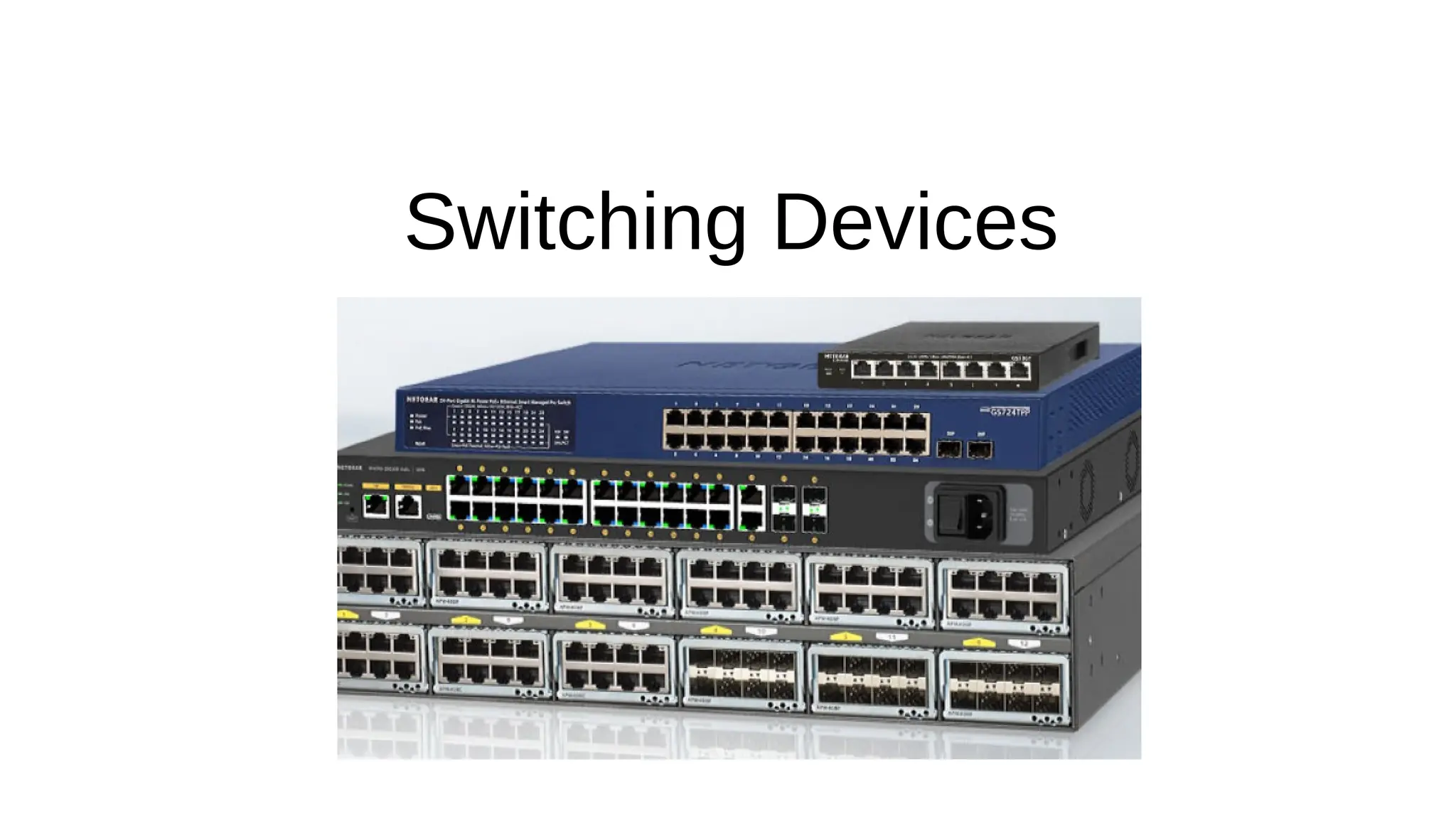
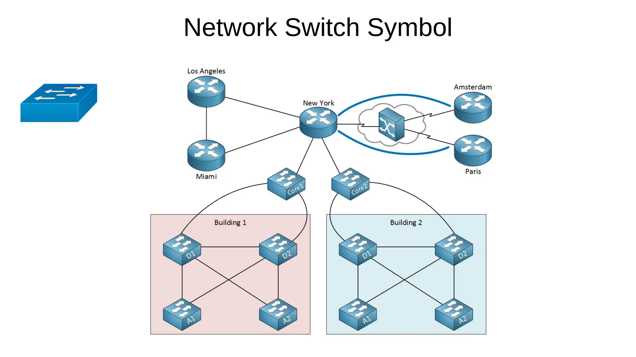
Network Switches
Definition:
Networkswitching devices are hardware components that connect devices in a network and facilitate the
transfer of data between them.
OSI layer of operation
Layer 2 switch - operate at the data link layer (Layer 2) of the OSI model.
Layer 3 switch – operate at both data link layer (Layer 2) or the network layer (Layer 3) of the OSI model.
Port density
Compact switches (8–16 ports) are commonly used in small offices or home networks.
Larger enterprise-grade switches can have 24, 48, or even more ports.
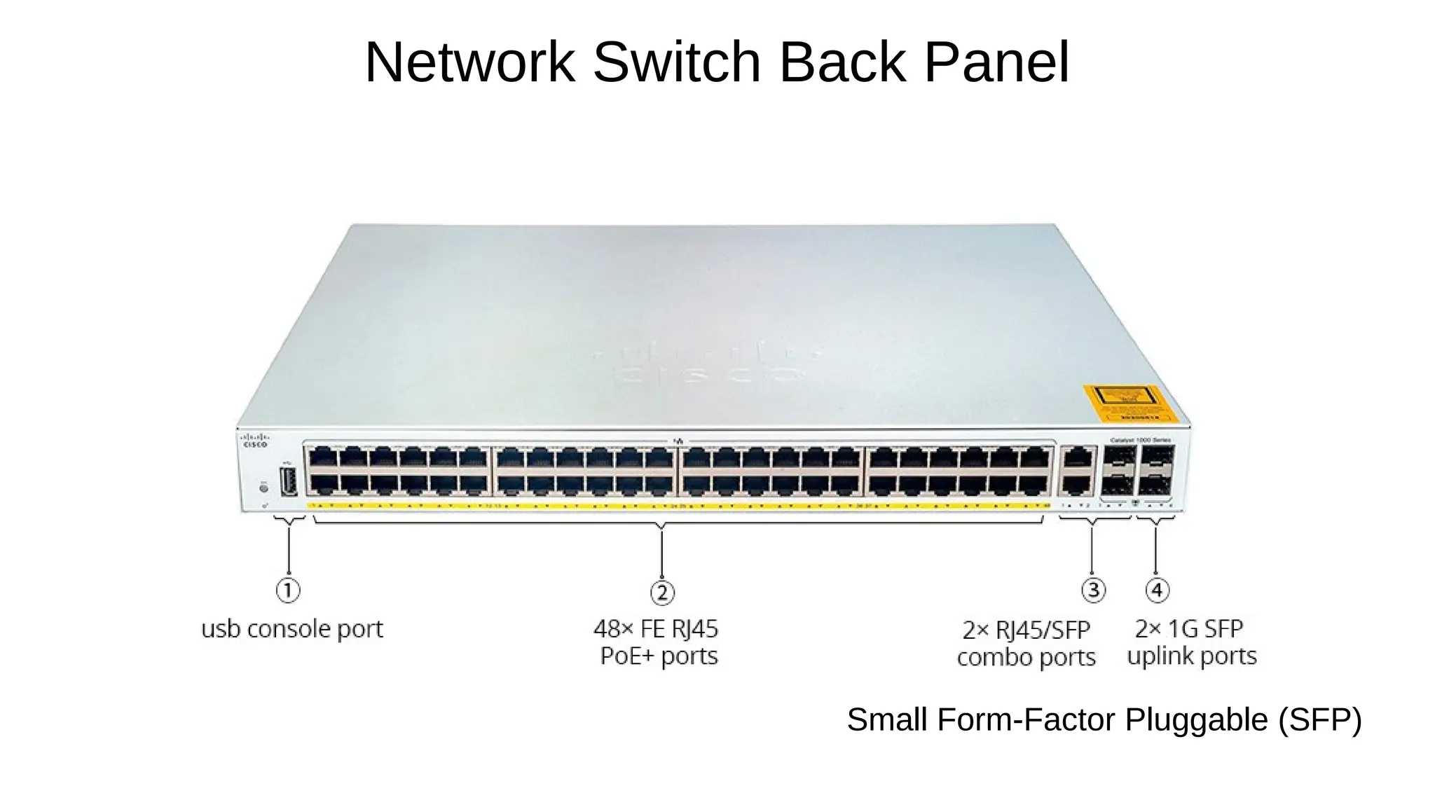
Port Type:
Ethernet (RJ45): Common for end-user devices.
SFP/SFP+: Used for high-speed uplinks or long-distance connections.
3.
Software switching
Anapplication software that relies on general-purpose processors (CPUs) to handle packet forwarding
Packet forwarding is implemented in software, making it highly customizable, upgradable, and patchable.
Provide slower performance limited by the processing power of the CPU, resulting in higher latency
Suitable for small networks or test environments where cost is a concern.
Hardware switching
Uses specialized hardware components like Application-Specific Integrated Circuits (ASICs) or Field-
Programmable Gate Arrays (FPGAs) to process and forward packets
Forwarding logic is implemented directly in the switch's hardware.
Hardware switching is significantly faster because packet forwarding is done in hardware rather than
software.
Higher Cost: Specialized hardware like ASICs increases the cost of the device
Suitable for large-scale networks with high traffic volumes i.e.
Data centers where performance and low latency are critical.
Backbone and core networks.
Switching Component Types
4.
Unmanaged Switches:
Simple,plug-and-play devices with no configuration options.
Operate at Layer 2 (data link layer).
Ideal for small networks or home use where traffic control isn't required.
Example:
NETGEAR GS105, TP-Link TL-SG1005D.
Managed Switches
Provide control over network traffic and offer advanced features like VLANs, Quality of Service (QoS), and
monitoring.
Can be configured and monitored via CLI, web interface, or SNMP.
Operate at Layer 2 (data link layer) or Layer 3 (network layer)
Suitable for larger or enterprise networks.
Example:
Cisco Catalyst series, Aruba 2930F, Juniper EX series.
Switch Types
Primary Function:
Operatesat the Data Link Layer (Layer 2) of the OSI model, focusing on switching and forwarding based on
MAC addresses.
Key Features:
MAC Address Table:
Maintains a table of MAC addresses and their associated ports.
Forwards frames based on MAC addresses.
Broadcast Domains:
By default, all ports belong to the same broadcast domain unless VLANs are configured.
Can create multiple VLANs to segment traffic.
Routing Capability:
No support for IP routing.
Relies on a router for inter-VLAN communication.
Layer 2 Switch
8.
Speed:
Ideal forlow to medium network traffic.
Used in smaller networks or at the Access Layer in hierarchical design.
Cost:
Less expensive compared to Layer 3 switches.
Suitable for environments with basic connectivity needs.
Example Use Case:
Connecting workstations, printers, and IP phones within the same VLAN.
Layer 2 Switch contd
9.
Primary Function:
Operatesat both the Data Link Layer (Layer 2) and the Network Layer (Layer 3), performing both switching and routing
based on IP addresses.
Key Features:
MAC Address Table:
Maintains a table of MAC addresses and their associated ports.
Forwards frames based on MAC addresses.
IP Routing:
Supports both static routing and routing protocols (e.g., OSPF, EIGRP, RIP).
Can route traffic between VLANs without needing a separate router (Inter-VLAN Routing).
Broadcast Domains:
Divides broadcast domains by enabling routing between VLANs.
Each VLAN is treated as a separate subnet.
Layer 3 Switch
10.
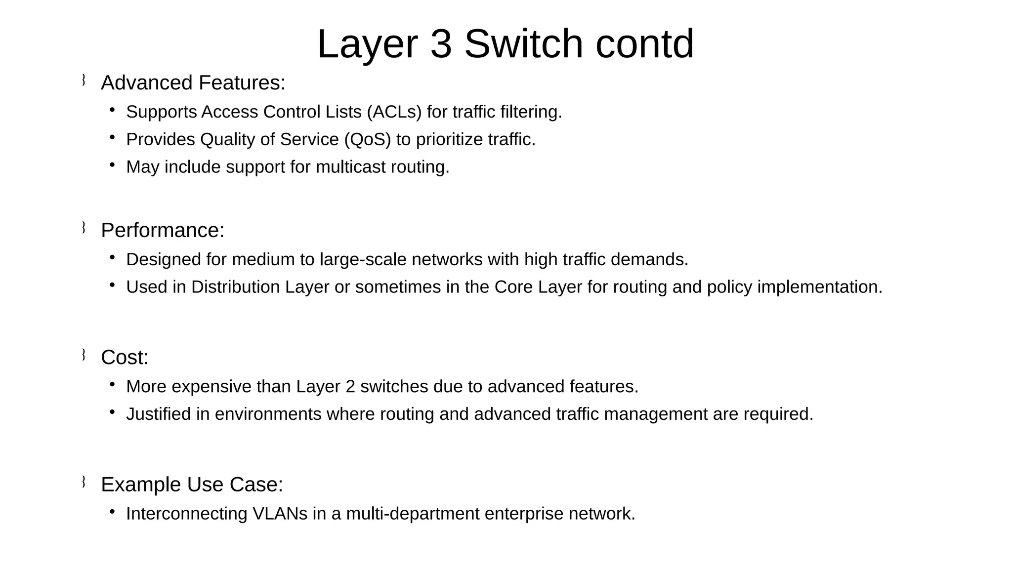
Advanced Features:
SupportsAccess Control Lists (ACLs) for traffic filtering.
Provides Quality of Service (QoS) to prioritize traffic.
May include support for multicast routing.
Performance:
Designed for medium to large-scale networks with high traffic demands.
Used in Distribution Layer or sometimes in the Core Layer for routing and policy implementation.
Cost:
More expensive than Layer 2 switches due to advanced features.
Justified in environments where routing and advanced traffic management are required.
Example Use Case:
Interconnecting VLANs in a multi-department enterprise network.
Layer 3 Switch contd
11.
Address learning refersto the process by which a
network switch learns and builds a MAC address table
(also called a forwarding table) to efficiently forward
Ethernet frames to their intended destinations.
This mechanism is fundamental to how Layer 2
switches operate and ensures optimal network
performance by reducing unnecessary traffic.
Address Learning in Switches
12.
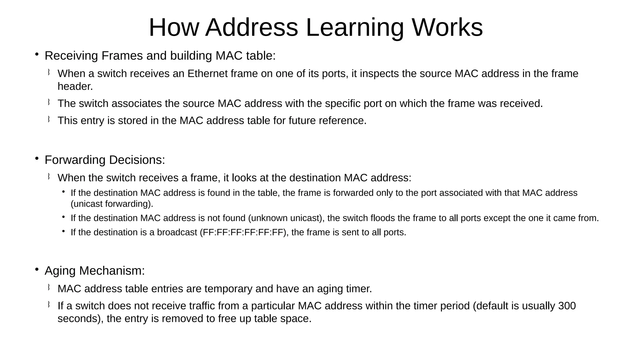
Receiving Frames andbuilding MAC table:
When a switch receives an Ethernet frame on one of its ports, it inspects the source MAC address in the frame
header.
The switch associates the source MAC address with the specific port on which the frame was received.
This entry is stored in the MAC address table for future reference.
Forwarding Decisions:
When the switch receives a frame, it looks at the destination MAC address:
If the destination MAC address is found in the table, the frame is forwarded only to the port associated with that MAC address
(unicast forwarding).
If the destination MAC address is not found (unknown unicast), the switch floods the frame to all ports except the one it came from.
If the destination is a broadcast (FF:FF:FF:FF:FF:FF), the frame is sent to all ports.
Aging Mechanism:
MAC address table entries are temporary and have an aging timer.
If a switch does not receive traffic from a particular MAC address within the timer period (default is usually 300
seconds), the entry is removed to free up table space.
How Address Learning Works


![Vibe Coding vs. Spec-Driven Development [Free Meetup]](https://cdn.slidesharecdn.com/ss_thumbnails/vibecodingvsspecdrivendevelopment-251209105622-43f455e7-thumbnail.jpg?width=640&height=640&fit=bounds)


