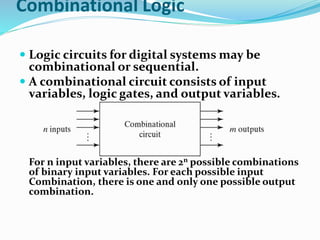
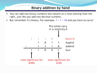
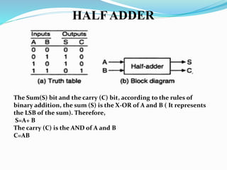
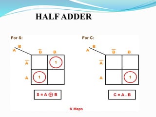
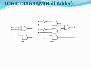
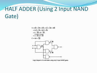
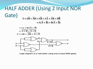
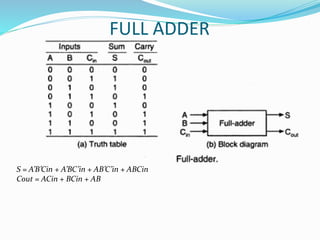
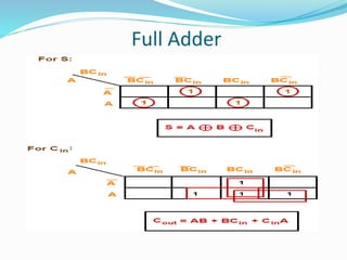
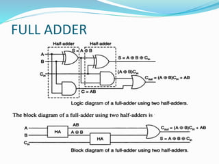
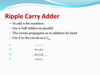
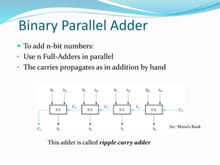
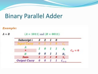
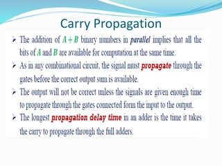
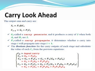
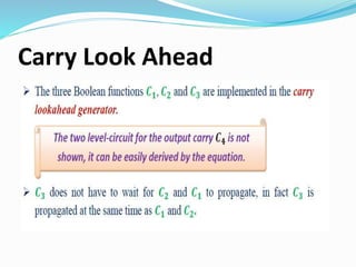
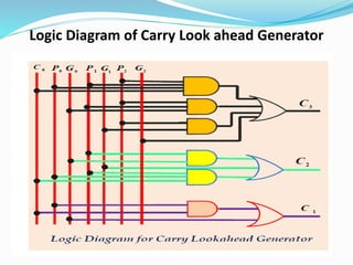
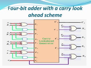
By Avadhesh Dixit
Combinational Logic
 Logic circuits for digital systems may be
combinational or sequential.
 A combinational circuit consists of input
variables, logic gates, and output variables.
For n input variables, there are 2n possible combinations
of binary input variables. For each possible input
Combination, there is one and only one possible output
combination.
HALFADDER
The Sum(S) bit and the carry (C) bit, according to the rules of
binary addition, the sum (S) is the X-OR of A and B ( It represents
the LSB of the sum). Therefore,
S=A+ B
The carry (C) is the AND of A and B
C=AB
HALFADDER
LOGIC DIAGRAM(Half Adder)
HALF ADDER (Using 2 Input NAND
Gate)
HALF ADDER (Using 2 Input NOR
Gate)
Limitation of Half Adder
 Half adders have no scope of adding the carry bit
resulting from the addition of previous bits.
 This is a major drawback of half adders.
 This is because real time scenarios involve adding the
multiple number of bits which can not be
accomplished using half adders.
 To overcome this drawback, Full Adder comes into
play.
FULL ADDER
 A Full-adder is a combinational circuit that adds two bits
and a carry and outputs a sum bit and a carry bit
 The full-adder adds the bits A and B and the carry from the
previous column called the carry-in Cin and outputs the
sum bit S and the carry bit called the carry-out Cout . The
variable S gives the value of the least significant bit of the
sum. The variable Cout gives the output carry.
 The eight rows under the input variables designate all
possible combinations of 1s and 0s that these variables may
have
FULL ADDER
S = A’B’Cin + A’BC’in + AB’C’in + ABCin
Cout = ACin + BCin + AB
Full Adder
FULL ADDER
Bigger Adders
• How to build an adder for n-bit numbers?
• Example: 4-Bit Adder
• Inputs ? 9 inputs
• Outputs ? 5 outputs
• What is the size of the truth table? 512 rows!
• How many functions to optimize? 5 functions
Ripple Carry Adder
 To add n-bit numbers:
• Use n Full-Adders in parallel
• The carries propagates as in addition by hand
• Use Z in the circuit as a Cin
 1 0 0 0
 0 1 0 1
 0 1 1 0
 1 0 1 1
Binary Parallel Adder
 To add n-bit numbers:
• Use n Full-Adders in parallel
• The carries propagates as in addition by hand
This adder is called ripple carry adder
Src: Mano’s Book
Binary Parallel Adder
Carry Propagation
Carry Propagation
How to add faster
 The most significant Sum bit of the adder is a function
of all the inputs.
 Could just do a straight logic equation for each Sum bit
as a function of all the bits of which it is a function.
 Or use a methodology
 That methodology is called carry-lookahead
Carry Look Ahead
Carry Look Ahead
Logic Diagram of Carry Look ahead Generator
Four-bit adder with a carry look
ahead scheme

1d-HALF ADDER & FULL ADDER-PPT.pdf

  • 1.
  • 2.
    Combinational Logic  Logiccircuits for digital systems may be combinational or sequential.  A combinational circuit consists of input variables, logic gates, and output variables. For n input variables, there are 2n possible combinations of binary input variables. For each possible input Combination, there is one and only one possible output combination.
  • 4.
    HALFADDER The Sum(S) bitand the carry (C) bit, according to the rules of binary addition, the sum (S) is the X-OR of A and B ( It represents the LSB of the sum). Therefore, S=A+ B The carry (C) is the AND of A and B C=AB
  • 5.
  • 6.
  • 7.
    HALF ADDER (Using2 Input NAND Gate)
  • 8.
    HALF ADDER (Using2 Input NOR Gate)
  • 9.
    Limitation of HalfAdder  Half adders have no scope of adding the carry bit resulting from the addition of previous bits.  This is a major drawback of half adders.  This is because real time scenarios involve adding the multiple number of bits which can not be accomplished using half adders.  To overcome this drawback, Full Adder comes into play.
  • 10.
    FULL ADDER  AFull-adder is a combinational circuit that adds two bits and a carry and outputs a sum bit and a carry bit  The full-adder adds the bits A and B and the carry from the previous column called the carry-in Cin and outputs the sum bit S and the carry bit called the carry-out Cout . The variable S gives the value of the least significant bit of the sum. The variable Cout gives the output carry.  The eight rows under the input variables designate all possible combinations of 1s and 0s that these variables may have
  • 11.
    FULL ADDER S =A’B’Cin + A’BC’in + AB’C’in + ABCin Cout = ACin + BCin + AB
  • 12.
  • 13.
  • 14.
    Bigger Adders • Howto build an adder for n-bit numbers? • Example: 4-Bit Adder • Inputs ? 9 inputs • Outputs ? 5 outputs • What is the size of the truth table? 512 rows! • How many functions to optimize? 5 functions
  • 15.
    Ripple Carry Adder To add n-bit numbers: • Use n Full-Adders in parallel • The carries propagates as in addition by hand • Use Z in the circuit as a Cin  1 0 0 0  0 1 0 1  0 1 1 0  1 0 1 1
  • 16.
    Binary Parallel Adder To add n-bit numbers: • Use n Full-Adders in parallel • The carries propagates as in addition by hand This adder is called ripple carry adder Src: Mano’s Book
  • 17.
  • 18.
  • 19.
  • 20.
    How to addfaster  The most significant Sum bit of the adder is a function of all the inputs.  Could just do a straight logic equation for each Sum bit as a function of all the bits of which it is a function.  Or use a methodology  That methodology is called carry-lookahead
  • 21.
  • 22.
  • 23.
    Logic Diagram ofCarry Look ahead Generator
  • 24.
    Four-bit adder witha carry look ahead scheme