SlideShare a Scribd company logo
2008 STEERING
Power Steering - Ranger
SPECIFICATIONS
MATERIAL SPECIFICATIONS
a Capacities listed are average system capacities and may vary.
TORQUE SPECIFICATIONS
DESCRIPTION & OPERATION
POWER STEERING
The power steering system consists of the following components:
 Power steering pump
 Power steering fluid reservoir
 Power steering pressure and return lines/hoses
Item Specification Fill Capacity
MERCON® V Automatic
Transmission Fluid
XT-5-QM (or XT-5-QMC) (US);
CXT-5-LM12 (Canada)
MERCON® V 1L (2.1 pt)a
Premium Long-Life Grease
XG-1-C or XG-1-K (US); CXG-1-
C (Canada)
ESA-M1C75-B -
Description Nm lb-ft
Inner tie rod 100 74
Lower steering column shaft-to-steering gear bolt 55 41
Outer tie-rod end nut 80 59
Power steering fluid cooler nuts 40 30
Power steering fluid reservoir bolts 14 10
Power steering fluid reservoir nut (3.0L) 14 10
Pressure line-to-pump fitting 65 48
Power steering pump bolts (2.3L) 23 17
Power steering pump bolts (3.0L and 4.0L) 25 18
Power steering pump pulley bolts (3.0L and 4.0L) 25 18
Steering gear nuts 150 111
Steering line clamp plate nut 35 26
Tie-rod jam nut 80 59
2008 Ford Ranger
2008 STEERING Power Steering - Ranger
2008 Ford Ranger
2008 STEERING Power Steering - Ranger
Microsoft
Wednesday, November 11, 2009 11:21:15 AM Page 1 © 2005 Mitchell Repair Information Company, LLC.
Microsoft
Wednesday, November 11, 2009 11:21:20 AM Page 1 © 2005 Mitchell Repair Information Company, LLC.
 Power steering fluid cooler
 Power steering gear
 Inner tie rod
The power steering system uses a vane-type pump to move the fluid from the reservoir to the steering gear and
through the rest of the steering hydraulic system. The power steering pump is mounted to the engine and driven
by the engine accessory drive belt. Power steering fluid flows into the pump from the reservoir. The power
steering fluid is then trapped between the pump vanes and moved to the high-pressure side of the pump creating
a flow of fluid. The restriction of this flow by the steering gear creates the pressure that provides the steering
assist. A combined pressure relief/flow valve is built into the pump to control the maximum pressure and flow
provided to the steering system. This action prevents damage to the system and provides the correct level of
assist during all engine speeds. While under pressure, the power steering fluid flows through the high-pressure
power steering line to the steering gear. The fluid exits the gear and flows through the return line, cooler and
finally to the reservoir. The reservoir slows the fluid, allows air to escape and filters the fluid before returning it
to the pump.
DIAGNOSTIC TESTS
POWER STEERING
Refer to STEERING SYSTEM - GENERAL INFORMATION article.
REMOVAL & INSTALLATION
POWER STEERING FLUID RESERVOIR - 2.3L & 4.0L
Material
Item Specification
MERCON® V Automatic Transmission Fluid
XT-5-QM (or XT-5-QMC) (US); CXT-5-LM12
(Canada)
MERCON® V
2008 Ford Ranger
2008 STEERING Power Steering - Ranger
Microsoft
Wednesday, November 11, 2009 11:21:15 AM Page 2 © 2005 Mitchell Repair Information Company, LLC.
Fig. 1: Identifying Power Steering Fluid Reservoir - 2.3L With Torque Specifications
Courtesy of FORD MOTOR CO.
Item Part Number Description
1 W503924
Power steering fluid reservoir bolts (3
required)
2 3R700 Power steering fluid reservoir
3 3A713 Return hose
4 3659 Power steering pump supply hose
2008 Ford Ranger
2008 STEERING Power Steering - Ranger
Microsoft
Wednesday, November 11, 2009 11:21:15 AM Page 3 © 2005 Mitchell Repair Information Company, LLC.
Fig. 2: Exploded View Of Power Steering Fluid Reservoir - 4.0L Engine With Torque Specifications
Courtesy of FORD MOTOR CO.
REMOVAL & INSTALLATION
Item Part Number Description
1 3659 Power steering pump supply hose
2 3A005 Return hose
3 N606678
Power steering fluid reservoir bolts (2
required)
4 3R700 Power steering fluid reservoir
CAUTION: While repairing the power steering system, care should be taken to
prevent the entry of foreign material or failure of the power steering
2008 Ford Ranger
2008 STEERING Power Steering - Ranger
Microsoft
Wednesday, November 11, 2009 11:21:15 AM Page 4 © 2005 Mitchell Repair Information Company, LLC.
All vehicles
1. Using a suitable suction device, remove the power steering fluid from the reservoir.
2. Compress the clamp and disconnect the return hose.
3. Compress the clamp and disconnect the power steering pump supply hose.
2.3L engines
4. Remove the 3 bolts and the power steering fluid reservoir.
 To install, tighten to 14 Nm (10 lb-ft).
4.0L engines
5. Remove the 2 bolts and the power steering fluid reservoir.
 To install, tighten to 14 Nm (10 lb-ft).
All vehicles
6. To install, reverse the removal procedure.
7. Fill the power steering system. For additional information, refer to STEERING SYSTEM - GENERAL
INFORMATION article.
POWER STEERING FLUID RESERVOIR - 3.0L
Material
components may result.
CAUTION: Do not allow power steering fluid to contact the engine accessory
drive belt or the belt may be damaged.
Item Specification
MERCON® V Automatic Transmission Fluid
XT-5-QM (or XT-5-QMC) (US); CXT-5-LM12
(Canada)
MERCON® V
2008 Ford Ranger
2008 STEERING Power Steering - Ranger
Microsoft
Wednesday, November 11, 2009 11:21:15 AM Page 5 © 2005 Mitchell Repair Information Company, LLC.
Fig. 3: Exploded View Of Power Steering Fluid Reservoir - 3.0L Engine With Torque Specifications
Courtesy of FORD MOTOR CO.
REMOVAL & INSTALLATION
Item Part Number Description
1 W503923
Power steering fluid reservoir bolts (2
required)
2 W520101 Power steering fluid reservoir nut
3 3R700 Power steering fluid reservoir
4 CS7617 Power steering pump supply hose
5 3F731 Return hose
CAUTION: While repairing the power steering system, care should be taken to
2008 Ford Ranger
2008 STEERING Power Steering - Ranger
Microsoft
Wednesday, November 11, 2009 11:21:15 AM Page 6 © 2005 Mitchell Repair Information Company, LLC.
1. Using a suitable suction device, remove the power steering fluid from the reservoir.
2. Compress the clamp and disconnect the return hose.
3. Compress the clamp and disconnect the power steering pump supply hose.
4. Remove the power steering fluid reservoir nut.
 To install, tighten to 14 Nm (10 lb-ft).
5. Remove the 2 bolts and the power steering fluid reservoir.
 To install, tighten to 14 Nm (10 lb-ft).
6. To install, reverse the removal procedure.
7. Fill the power steering system. For additional information, refer to STEERING SYSTEM - GENERAL
INFORMATION article.
POWER STEERING PUMP - 2.3L
Special Tools
Material
prevent the entry of foreign material or failure of the power steering
components may result.
CAUTION: Do not allow power steering fluid to contact the engine accessory
drive belt or the belt may be damaged.
Illustration Tool Name Tool Number
Installer Set, Teflon® Seal
211-D027 (D90P-3517-A) or
equivalent
Item Specification
MERCON® V Automatic Transmission Fluid
XT-5-QM (or XT-5-QMC) (US); CXT-5-LM12
(Canada)
MERCON® V
2008 Ford Ranger
2008 STEERING Power Steering - Ranger
Microsoft
Wednesday, November 11, 2009 11:21:15 AM Page 7 © 2005 Mitchell Repair Information Company, LLC.
Fig. 4: Identifying Power Steering Pump - 2.3L With Torque Specifications
Courtesy of FORD MOTOR CO.
REMOVAL & INSTALLATION
1. Using a suitable suction device, remove the power steering fluid from the reservoir.
2. Remove the power steering pump pulley. For additional information, refer to Power Steering Pump
Pulley - 2.3L.
3. Compress the clamp and disconnect the power steering pump supply hose.
Item Part Number Description
1 3A719 Pressure line-to-pump fitting
2 W705952 Power steering pump bolt (4 required)
3 C56697 Power steering pump supply hose
4 3A674 Power steering pump
5 N803257 Teflon® seal
CAUTION: While repairing the power steering system, care should be taken to
prevent the entry of foreign material or failure of the power steering
components may result.
CAUTION: Do not allow power steering fluid to contact the accessory drive belt
or the belt may be damaged.
2008 Ford Ranger
2008 STEERING Power Steering - Ranger
Microsoft
Wednesday, November 11, 2009 11:21:15 AM Page 8 © 2005 Mitchell Repair Information Company, LLC.
4. Disconnect the pressure line-to-pump fitting.
 Remove and discard the Teflon® seal.
 To install, tighten to 65 Nm (48 lb-ft).
5. Remove the 4 power steering pump bolts and the power steering pump.
 To install, tighten to 23 Nm (17 lb-ft).
6. To install, reverse the removal procedure.
 Using the special tool, install a new Teflon® seal on the pressure line-to-pump fitting.
 Fill the power steering system. For additional information, refer to STEERING SYSTEM -
GENERAL INFORMATION article.
Fig. 5: Installing Teflon(R) Seal Using Special Tool
Courtesy of FORD MOTOR CO.
POWER STEERING PUMP - 3.0L
Special Tools
Material
CAUTION: A new Teflon® seal must be installed any time the pressure line
fitting is disconnected from the power steering pump or a fluid leak
may occur.
Illustration Tool Name Tool Number
Installer Set, Teflon® Seal
211-D027 (D90P-3517-A) or
equivalent
Item Specification
MERCON® V Automatic Transmission Fluid
XT-5-QM (or XT-5-QMC) (US); CXT-5-LM12
(Canada)
MERCON® V
2008 Ford Ranger
2008 STEERING Power Steering - Ranger
Microsoft
Wednesday, November 11, 2009 11:21:15 AM Page 9 © 2005 Mitchell Repair Information Company, LLC.
Fig. 6: Exploded View Of Power Steering Pump - 3.0L Engine With Torque Specifications
Courtesy of FORD MOTOR CO.
REMOVAL & INSTALLATION
1. Using a suitable suction device, remove the power steering fluid from the reservoir.
2. Remove the power steering pump pulley. For additional information, refer to Power Steering Pump
Pulley - 3.0L, 4.0L.
3. Disconnect the pressure line-to-pump fitting.
Item Part Number Description
1 N605784 Power steering pump bolt (3 required)
2 3R700 Power steering fluid reservoir
3 CS7617 Power steering pump supply hose
4 3A674 Power steering pump
5 N803257 Teflon® seal
6 3A719 Pressure line-to-pump fitting
CAUTION: While repairing the power steering system, care should be taken to
prevent the entry of foreign material or failure of the power steering
components may result.
CAUTION: Do not allow power steering fluid to contact the engine accessory
drive belt or the belt may be damaged.
2008 Ford Ranger
2008 STEERING Power Steering - Ranger
Microsoft
Wednesday, November 11, 2009 11:21:16 AM Page 10 © 2005 Mitchell Repair Information Company, LLC.
 Remove and discard the Teflon® seal.
 To install, tighten to 65 Nm (48 lb-ft).
4. Compress the clamp and disconnect the power steering pump supply hose.
5. Remove the 3 bolts and the power steering pump.
 To install, tighten to 25 Nm (18 lb-ft).
6. To install, reverse the removal procedure.
 Using the special tool, install a new Teflon® seal on the pressure line-to-pump fitting.
 Fill the power steering system. For additional information, refer to STEERING SYSTEM -
GENERAL INFORMATION article.
Fig. 7: Installing Teflon(R) Seal Using Special Tool
Courtesy of FORD MOTOR CO.
POWER STEERING PUMP - 4.0L
Special Tools
Material
CAUTION: A new Teflon® seal must be installed any time the pressure line
fitting is disconnected from the power steering pump or a fluid leak
may occur.
Illustration Tool Name Tool Number
Installer Set, Teflon® Seal
211-D027 (D90P-3517-A) or
equivalent
Item Specification
MERCON® V Automatic Transmission Fluid
XT-5-QM (or XT-5-QMC) (US); CXT-5-LM12
(Canada)
MERCON® V
2008 Ford Ranger
2008 STEERING Power Steering - Ranger
Microsoft
Wednesday, November 11, 2009 11:21:16 AM Page 11 © 2005 Mitchell Repair Information Company, LLC.
Fig. 8: Exploded View Of Power Steering Pump - 4.0L With Torque Specifications
Courtesy of FORD MOTOR CO.
REMOVAL & INSTALLATION
1. Using a suitable suction device, remove the power steering fluid from the reservoir.
2. Remove the engine cooling fan. For additional information, refer to ENGINE COOLING article.
3. Remove the power steering pump pulley. For additional information, refer to Power Steering Pump
Pulley - 3.0L, 4.0L.
Item Part Number Description
1 3A719 Pressure line-to-pump fitting
2 3659 Power steering pump supply hose
3 W700839 Power steering pump bolt (3 required)
4 3A674 Power steering pump
5 N803257 Teflon® seal
CAUTION: While repairing the power steering system, care should be taken to
prevent the entry of foreign material or failure of the power steering
components may result.
CAUTION: Do not allow power steering fluid to contact the accessory drive belt
or the belt may be damaged.
2008 Ford Ranger
2008 STEERING Power Steering - Ranger
Microsoft
Wednesday, November 11, 2009 11:21:16 AM Page 12 © 2005 Mitchell Repair Information Company, LLC.
4. Compress the clamp and disconnect the power steering pump supply hose from the power steering fluid
reservoir.
5. Disconnect the pressure line-to-pump fitting.
 To install, tighten to 65 Nm (48 lb-ft).
6. Compress the clamp and disconnect the power steering pump supply hose from the power steering pump.
7. Remove the 3 bolts and the power steering pump.
 Tighten to 25 Nm (18 lb-ft).
8. To install, reverse removal procedure.
 Using the special tool, install a new Teflon® seal on the pressure line-to-pump fitting.
 Fill the power steering system. For additional information, refer to STEERING SYSTEM -
GENERAL INFORMATION article.
Fig. 9: Installing Teflon(R) Seal Using Special Tool
Courtesy of FORD MOTOR CO.
POWER STEERING PUMP PULLEY - 2.3L
Special Tools
CAUTION: A new Teflon® seal must be installed any time the pressure line is
disconnected from the power steering pump or a fluid leak may
occur.
Illustration Tool Name Tool Number
Remover, Power Steering Pump
Pulley
211-016 (T69L-10300-B)
Installer, Power Steering Pump
Pulley
211-185 (T91P-3A733-A)
2008 Ford Ranger
2008 STEERING Power Steering - Ranger
Microsoft
Wednesday, November 11, 2009 11:21:16 AM Page 13 © 2005 Mitchell Repair Information Company, LLC.
Fig. 10: Identifying Power Steering Pump Pulley - 2.3L
Courtesy of FORD MOTOR CO.
REMOVAL
1. Remove the air cleaner outlet pipe. For additional information, refer to INTAKE AIR DISTRIBUTION
& FILTERING article.
2. Rotate the accessory drive belt tensioner counterclockwise and position the accessory drive belt aside.
Item Part Number Description
1 3D673 Power steering pump pulley
2 8620 Accessory drive belt
2008 Ford Ranger
2008 STEERING Power Steering - Ranger
Microsoft
Wednesday, November 11, 2009 11:21:16 AM Page 14 © 2005 Mitchell Repair Information Company, LLC.
Fig. 11: Locating Accessory Drive Belt Tensioner
Courtesy of FORD MOTOR CO.
3. Using the special tool, remove the power steering pump pulley.
Fig. 12: Removing Pulley Using Special Tool (211-016)
Courtesy of FORD MOTOR CO.
INSTALLATION
1. Using the special tool, install the power steering pump pulley.
CAUTION: Do not install a power steering pump pulley that has been removed
and installed twice or pulley failure and/or pump damage may occur.
Inspect the pulley for paint marks in the web area near the hub. If
there are 2 paint marks, discard the pulley and install a new one. If
there is 1 paint mark or no paint marks, use a paint pencil to mark the
web area of the pulley near the hub.
2008 Ford Ranger
2008 STEERING Power Steering - Ranger
Microsoft
Wednesday, November 11, 2009 11:21:16 AM Page 15 © 2005 Mitchell Repair Information Company, LLC.
Fig. 13: Installing Pulley Using Special Tool (211-185)
Courtesy of FORD MOTOR CO.
2. Rotate the tensioner counterclockwise and position the belt on the power steering pump pulley.
Fig. 14: Locating Accessory Drive Belt Tensioner
Courtesy of FORD MOTOR CO.
3. Install the air cleaner outlet pipe. For additional information, refer to INTAKE AIR DISTRIBUTION &
FILTERING article.
POWER STEERING PUMP PULLEY - 3.0L, 4.0L
NOTE: For additional information on accessory drive belt routing, refer to
ACCESSORY DRIVE article.
2008 Ford Ranger
2008 STEERING Power Steering - Ranger
Microsoft
Wednesday, November 11, 2009 11:21:16 AM Page 16 © 2005 Mitchell Repair Information Company, LLC.
Fig. 15: Identifying Power Steering Pump Pulley - 3.0L, 4.0L With Torque Specifications
Courtesy of FORD MOTOR CO.
REMOVAL & INSTALLATION
1. Loosen the power steering pump pulley bolts.
2. Rotate the accessory drive belt tensioner counterclockwise and position the accessory drive belt aside.
3. Remove the 3 bolts and the power steering pump pulley.
 To install, tighten to 25 Nm (18 lb-ft).
4. To install, reverse the removal procedure.
INNER TIE ROD
Item Part Number Description
1 N605784
Power steering pump pulley bolts (3
required)
2 3A733 Power steering pump pulley
3 8620 Accessory drive belt
NOTE: 4.0L engine shown in illustration, 3.0L engine similar.
NOTE: For additional information on accessory drive belt routing, refer to
ACCESSORY DRIVE article.
2008 Ford Ranger
2008 STEERING Power Steering - Ranger
Microsoft
Wednesday, November 11, 2009 11:21:16 AM Page 17 © 2005 Mitchell Repair Information Company, LLC.
Special Tools
Material
Fig. 16: Identifying Inner Tie Rod With Torque Specifications
Courtesy of FORD MOTOR CO.
Illustration Tool Name Tool Number
Inner Tie-Rod Socket Tool 211-D029 or equivalent
Tie-Rod End Separator
211-105 (T85M-3395-A) or
equivalent
Item Specification
Premium Long-Life Grease
XG-1-C or XG-1-K (US); CXG-1-C (Canada)
ESA-M1C75-B
Item Part Number Description
1 N803637
Tie-rod jam nut (part of 3280) (2
required)
2008 Ford Ranger
2008 STEERING Power Steering - Ranger
Microsoft
Wednesday, November 11, 2009 11:21:16 AM Page 18 © 2005 Mitchell Repair Information Company, LLC.
REMOVAL & INSTALLATION
Coil spring suspension vehicles
1. Remove the wheel and tire. For additional information, refer to WHEELS & TIRES article.
2. Loosen the tie-rod jam nuts.
 To install, tighten to 80 Nm (59 lb-ft).
3. Remove the outer tie-rod end cotter pin and nut.
 Discard the cotter pin.
 To install, tighten to 80 Nm (59 lb-ft).
4. Using the special tool, disconnect the outer tie-rod end.
2 N800895 Outer tie-rod end nut (2 required)
3 3290 Outer tie-rod end (2 required)
4 3K745 Outer bellows boot clamp (2 required)
5 3C650A Inner bellows boot clamp (2 required)
6 3K661 Steering gear bellows boot (2 required)
7 3280 Inner tie rod (2 required)
8 N642569 Cotter pin (2 required)
CAUTION: The boots and clamps are designed to provide an airtight seal and protect
the internal components of the steering gear. If the seal is not airtight, the
vacuum generated during turning may draw water and foreign material
into the gear and damage internal components. Zip ties do not produce an
airtight seal and must not be used.
CAUTION: The inner ball joint grease is not compatible with water. Water and foreign
material trapped in the grease may damage the joint.
CAUTION: If present, the orientation of the vent tubes must be noted so the boots
and vent tubes may be installed in their original locations. Incorrect
venting may lead to internal component damage.
CAUTION: Do not damage the tie-rod end boot when installing the special tool.
2008 Ford Ranger
2008 STEERING Power Steering - Ranger
Microsoft
Wednesday, November 11, 2009 11:21:16 AM Page 19 © 2005 Mitchell Repair Information Company, LLC.
Fig. 17: Identifying Special Tool On Tie-Rod End
Courtesy of FORD MOTOR CO.
5. Remove the outer tie-rod end.
6. Remove the tie-rod jam nut.
7. Remove the inner and outer bellows boot clamps.
8. Remove the bellows boot.
9. Using the special tool, remove the inner tie rod.
 To install, tighten to 100 Nm (74 lb-ft).
NOTE: Count and record the number of times the outer tie-rod end turns for
assembly reference.
NOTE: If repairing the RH side, it will be necessary to pull back the LH inner
bellows boot to hold the steering gear.
CAUTION: Place the steering gear at the center position. Use a 21 mm (0.82 in)
crowfoot on the flat of the rack gear to resist rotation and to prevent
damage during removal and installation of the inner tie rod.
NOTE: The help of an assistant may be needed for removal of the RH inner tie
rod.
2008 Ford Ranger
2008 STEERING Power Steering - Ranger
Microsoft
Wednesday, November 11, 2009 11:21:16 AM Page 20 © 2005 Mitchell Repair Information Company, LLC.
Fig. 18: Inner Tie Rod And Special Tool
Courtesy of FORD MOTOR CO.
Torsion bar suspension vehicles
10. Loosen the tie-rod jam nut.
 To install, tighten to 80 Nm (59 lb-ft).
11. Remove the steering gear. For additional information, refer to Steering Gear - Rear Wheel Drive
(RWD) or Steering Gear - Four Wheel Drive (4WD).
12. Remove the outer tie-rod end and jam nut.
13. Remove the inner and outer bellows boot clamps.
14. Using the special tool, remove the inner tie rod.
 To install, tighten to 100 Nm (74 lb-ft).
Fig. 19: Locating Inner Tie Rod
Courtesy of FORD MOTOR CO.
All vehicles
NOTE: Count and record the number of times the outer tie-rod end turns for
assembly reference.
NOTE: If repairing the RH side, it will be necessary to pull back the LH inner
bellows boot to hold the steering gear.
CAUTION: Place the steering gear at the center position. Use a 21 mm (0.82 in)
crowfoot on the flat of the rack gear to resist rotation and to prevent
damage during removal and installation of the inner tie rod.
NOTE: The help of an assistant may be needed for removal of the RH inner tie
rod.
2008 Ford Ranger
2008 STEERING Power Steering - Ranger
Microsoft
Wednesday, November 11, 2009 11:21:16 AM Page 21 © 2005 Mitchell Repair Information Company, LLC.
15. Thoroughly clean and inspect all the parts to be reused. Install new parts as necessary.
16. Check that the bellows boot seal is positioned correctly over the steering gear housing bead at the large
inside diameter (ID) and is in the inner tie-rod groove at the small ID.
 Check that the bellows boot seal is not twisted and the breather tube is securely inserted into the
breather nipple at both bellows boots.
17. To install, reverse the removal procedure.
18. Check and if necessary adjust the front toe. For additional information, refer to SUSPENSION SYSTEM
- GENERAL INFORMATION article.
POWER STEERING FLUID COOLER
Material
CAUTION: Thoroughly remove any dirt or foreign material that is present. This
material is extremely harmful to the steering gear.
NOTE: Lubricate the inner tie rod inside groove with steering gear grease where
the bellows boot is clamped.
Item Specification
MERCON® V Automatic Transmission Fluid
XT-5-QM (or XT-5-QMC) (US); CXT-5-LM12
(Canada)
MERCON® V
2008 Ford Ranger
2008 STEERING Power Steering - Ranger
Microsoft
Wednesday, November 11, 2009 11:21:16 AM Page 22 © 2005 Mitchell Repair Information Company, LLC.
Fig. 20: Identifying Power Steering Fluid Cooler With Torque Specifications
Courtesy of FORD MOTOR CO.
REMOVAL & INSTALLATION
1. With the vehicle in NEUTRAL, position it on a hoist. For additional information, refer to JACKING &
LIFTING article.
2. Remove the 2 power steering fluid cooler nuts.
 To install, tighten to 40 Nm (30 lb-ft).
3. Compress the clamps and disconnect the 2 power steering fluid cooler hoses.
4. To install, reverse the removal procedure.
 Fill the power steering system. For additional information, refer to STEERING SYSTEM -
GENERAL INFORMATION article.
STEERING GEAR - REAR WHEEL DRIVE (RWD)
Special Tools
Item Part Number Description
1 3A713B Power steering fluid cooler hose
2 3A713A Power steering fluid cooler hose
3 N800169
Power steering fluid cooler nuts (2
required)
4 3F780 Power steering fluid cooler
CAUTION: While repairing the power steering system, care should be taken to
prevent the entry of foreign material or failure of the power steering
components may result.
Illustration Tool Name Tool Number
Remover, Tie-Rod End
211-001 (TOOL-3290-D) or
equivalent
2008 Ford Ranger
2008 STEERING Power Steering - Ranger
Microsoft
Wednesday, November 11, 2009 11:21:16 AM Page 23 © 2005 Mitchell Repair Information Company, LLC.
Fig. 21: Identifying Steering Gear - Rear Wheel Drive (RWD) With Torque Specifications
Courtesy of FORD MOTOR CO.
Item Part Number Description
1 W520413 Steering line clamp plate nut
2 3A713 Return line
3 3A719 Pressure line
4 N803256 O-ring seal
5 N803257 O-ring seal
6 N811762 Steering gear studs (2 required)
7 N803942
Lower steering column shaft-to-steering
gear bolt
8 3504 Steering gear
9 N808265 Steering gear nuts (2 required)
2008 Ford Ranger
2008 STEERING Power Steering - Ranger
Microsoft
Wednesday, November 11, 2009 11:21:16 AM Page 24 © 2005 Mitchell Repair Information Company, LLC.
REMOVAL & INSTALLATION
All vehicles
1. Remove the front wheels and tires. For additional information, refer to WHEELS & TIRES article.
2. Place the steering wheel in the straight-ahead position and remove the ignition key.
 Rotate the steering wheel until the steering column locks into position.
3.0L and 4.0L engines
3. Remove the power steering fluid cooler. For additional information, refer to Power Steering Fluid
Cooler.
All vehicles
4. Remove the outer tie-rod end cotter pins and nuts.
 Discard the cotter pins.
 To install, tighten to 80 Nm (59 lb-ft).
5. Using special tool, separate the outer tie-rod ends from the wheel spindles.
10 N642569 Cotter pin (2 required)
11 N800895 Outer tie-rod end nut (2 required)
CAUTION: When repairing the power steering system, care should be taken to
prevent the entry of foreign material or failure of the power steering
components may result.
CAUTION: Do not damage the tie-rod boot when installing the special tool.
NOTE: Remove the adapter from the ball end of the special tool. Apply a small
amount of grease to the tie-rod end stud and the ball of the special tool.
2008 Ford Ranger
2008 STEERING Power Steering - Ranger
Microsoft
Wednesday, November 11, 2009 11:21:16 AM Page 25 © 2005 Mitchell Repair Information Company, LLC.
Fig. 22: Separating Outer Tie Rods From Wheel Knuckles
Courtesy of FORD MOTOR CO.
6. Remove the lower steering column shaft-to-steering gear bolt and disconnect the lower steering column
shaft from the gear.
 Discard the bolt.
 To install, tighten to 55 Nm (41 lb-ft).
7. Remove the steering line clamp plate nut and disconnect the pressure and return lines.
 Discard the O-ring seals.
 To install, tighten to 35 Nm (26 lb-ft).
8. Plug or cap the return line, pressure line and the steering gear ports to prevent the entry of dirt.
9. Remove the 2 steering gear nuts and the 2 steering gear studs.
 To install, tighten to 150 Nm (111 lb-ft).
10. Remove the steering gear.
11. If necessary, remove the outer tie-rod ends.
12. To install, reverse the removal procedure.
 Install new power steering line O-ring seals.
13. Fill the power steering system. For additional information, refer to STEERING SYSTEM - GENERAL
INFORMATION article.
14. Check and, if necessary, adjust the front toe.
STEERING GEAR - FOUR WHEEL DRIVE (4WD)
Special Tools
CAUTION: Do not allow the steering column to rotate while the steering column
shaft is disconnected from the steering gear or damage to the
clockspring may result. If there is evidence that the steering column
has rotated, the clockspring must be removed and recentered. For
additional information, refer to SUPPLEMENTAL RESTRAINT
SYSTEM article.
CAUTION: Hold the tops of the steering gear studs to avoid damaging the
steering gear fluid transfer tubes.
CAUTION: New O-ring seals must be installed any time the power steering lines
are disconnected from the steering gear or a fluid leak may occur.
Illustration Tool Name Tool Number
2008 Ford Ranger
2008 STEERING Power Steering - Ranger
Microsoft
Wednesday, November 11, 2009 11:21:16 AM Page 26 © 2005 Mitchell Repair Information Company, LLC.
Fig. 23: Identifying Steering Gear - Four Wheel Drive (4WD) With Torque Specifications
Courtesy of FORD MOTOR CO.
Remover, Tie-Rod End
211-001 (TOOL-3290-D) or
equivalent
Item Part Number Description
1 W520413 Steering line clamp plate nut
2 3A713 Return line
3 3A719 Pressure line
4 N803256 O-ring seal
2008 Ford Ranger
2008 STEERING Power Steering - Ranger
Microsoft
Wednesday, November 11, 2009 11:21:16 AM Page 27 © 2005 Mitchell Repair Information Company, LLC.
REMOVAL
All vehicles
1. Remove the front wheels and tires. For additional information, refer to WHEELS & TIRES article.
2. Place the steering wheel in the straight-ahead position and remove the ignition key.
 Rotate the steering wheel until the steering column locks into position.
3.0L and 4.0L engines
3. Remove the power steering fluid cooler. For additional information, refer to Power Steering Fluid
Cooler.
All vehicles
4. Loosen the tie-rod jam nuts.
5. Remove the outer tie-rod end cotter pins and nuts.
 Discard the cotter pins.
6. Using the special tool, separate the outer tie-rod ends from the wheel knuckles.
5 N803257 O-ring seal
6 N811762 Steering gear studs (2 required)
7 N803942
Lower steering column shaft-to-steering
gear bolt
8 3504 Steering gear
9 N803637
Tie rod jam nut (part of 3280) (2
required)
10 N808265 Steering gear nuts (2 required)
11 3290 Outer tie-rod end (2 required)
12 N642569 Cotter pin (2 required)
13 N800895 Outer tie-rod end nut (2 required)
CAUTION: When repairing the power steering system, care should be taken to
prevent the entry of foreign material or failure of the power steering
components may result.
CAUTION: Do not damage the tie-rod boot when installing the special tool.
NOTE: Remove the adapter from the ball end of the special tool. Apply a small
amount of grease to the tie-rod end stud and the ball of the special tool.
2008 Ford Ranger
2008 STEERING Power Steering - Ranger
Microsoft
Wednesday, November 11, 2009 11:21:16 AM Page 28 © 2005 Mitchell Repair Information Company, LLC.
Fig. 24: Separating Outer Tie Rods From Wheel Knuckles
Courtesy of FORD MOTOR CO.
7. Remove the outer tie-rod ends.
 Count and record the number of turns required to remove the outer tie-rod end.
8. Remove the stabilizer bar and link. For additional information, refer to FRONT SUSPENSION - FOUR
WHEEL DRIVE (4WD) article.
9. Remove the lower steering column shaft-to-steering gear bolt and disconnect the shaft from the steering
gear.
 Discard the bolt.
10. Remove the steering line clamp plate nut and disconnect the pressure and return lines.
 Discard the O-ring seals.
11. Remove the 2 steering gear nuts and steering gear studs.
12. Rotate the steering gear control valve housing toward the front of the vehicle.
CAUTION: Do not allow the steering column to rotate while the steering column
shaft is disconnected from the steering gear or damage to the
clockspring may result. If there is evidence that the steering column
has rotated, the clockspring must be removed and recentered. For
additional information, refer to SUPPLEMENTAL RESTRAINT
SYSTEM article.
CAUTION: Hold the tops of the steering gear studs to avoid damaging the
steering gear fluid transfer tubes.
2008 Ford Ranger
2008 STEERING Power Steering - Ranger
Microsoft
Wednesday, November 11, 2009 11:21:16 AM Page 29 © 2005 Mitchell Repair Information Company, LLC.
Fig. 25: Rotating Steering Gear Control Valve Housing Toward Front Of Vehicle
Courtesy of FORD MOTOR CO.
13. Turn the steering gear input shaft to the right until the stop is reached.
14. Move the steering gear as far to the RH side of the vehicle as possible.
Fig. 26: Moving Steering Gear As Far To RH Side Of Vehicle As Possible
Courtesy of FORD MOTOR CO.
15. Move the LH inner tie rod forward to clear the frame crossmember.
Fig. 27: Locating LH Inner Tie Rod
Courtesy of FORD MOTOR CO.
16. Remove the steering gear.
2008 Ford Ranger
2008 STEERING Power Steering - Ranger
Microsoft
Wednesday, November 11, 2009 11:21:16 AM Page 30 © 2005 Mitchell Repair Information Company, LLC.
Fig. 28: Removing Steering Gear
Courtesy of FORD MOTOR CO.
INSTALLATION
All vehicles
1. Turn the steering gear input shaft to the right until the stop is reached. Count and record the number of
turns required.
2. Install the steering gear into the RH opening of the crossmember.
Fig. 29: Installing Steering Gear Into RH Opening Of Crossmember
Courtesy of FORD MOTOR CO.
CAUTION: Handle the steering gear with caution to avoid damage to fluid
transfer tubes and to avoid dimples in the steering gear bellows boot.
NOTE: Make sure the steering gear input shaft is turned to the left until the stop is
reached.
NOTE: Make sure the steering gear control valve housing is turned toward the
front of the vehicle.
CAUTION: Take care not to scuff or tear the steering gear bellows boots.
2008 Ford Ranger
2008 STEERING Power Steering - Ranger
Microsoft
Wednesday, November 11, 2009 11:21:16 AM Page 31 © 2005 Mitchell Repair Information Company, LLC.
3. Move the steering gear as far to the RH side of the vehicle as possible.
Fig. 30: Moving Steering Gear As Far To RH Side Of Vehicle As Possible
Courtesy of FORD MOTOR CO.
4. Move the LH inner tie rod into the opening in the crossmember and move the steering gear into position.
Fig. 31: Locating LH Inner Tie Rod
Courtesy of FORD MOTOR CO.
5. To place the steering gear in the straight-ahead position, turn the steering gear input shaft to the left by
1/2 the number of turns previously recorded.
6. Rotate the steering gear control valve housing toward the rear of the vehicle.
Fig. 32: Rotating Steering Gear Control Valve Housing Toward Rear Of Vehicle
Courtesy of FORD MOTOR CO.
7. Install the 2 steering gear studs.
2008 Ford Ranger
2008 STEERING Power Steering - Ranger
Microsoft
Wednesday, November 11, 2009 11:21:16 AM Page 32 © 2005 Mitchell Repair Information Company, LLC.
8. Install the 2 steering gear nuts.
 Tighten to 150 Nm (111 lb-ft).
9. Position the pressure and return lines and install the steering line clamp plate nut.
 Tighten to 35 Nm (26 lb-ft).
10. Connect the steering column shaft to the steering gear and install a new bolt.
 Tighten to 55 Nm (41 lb-ft).
11. Install the stabilizer bar and link. For additional information, refer to FRONT SUSPENSION - FOUR
WHEEL DRIVE (4WD) article.
12. Install the outer tie-rod ends.
 Rotate the outer tie-rod ends the number of turns recorded during removal.
13. Position the outer tie-rod ends and install the nuts and new cotter pins.
 Check that the brake disc shields are not bent and are not in contact with the outer tie-rod end
boots.
 Tighten to 80 Nm (59 lb-ft).
3.0L and 4.0L engines
14. Install the power steering fluid cooler. For additional information, refer to Power Steering Fluid Cooler.
All vehicles
15. Tighten the tie-rod jam nuts.
 Tighten to 80 Nm (59 lb-ft).
16. Fill the power steering system. For additional information, refer to STEERING SYSTEM - GENERAL
INFORMATION article.
17. Check and, if necessary, adjust the front toe. For additional information, refer to SUSPENSION
SYSTEM - GENERAL INFORMATION article.
CAUTION: Hold the tops of the steering gear studs to avoid damaging the
steering gear fluid transfer tubes.
CAUTION: New O-rings must be installed any time the lines are disconnected
from the steering gear or a fluid leak may occur.
CAUTION: Do not allow the steering column to rotate while the steering column
shaft is disconnected from the steering gear or damage to the
clockspring may result. If there is evidence that the steering column
has rotated, the clockspring must be removed and re-centered. For
additional information, refer to SUPPLEMENTAL RESTRAINT
SYSTEM article.
2008 Ford Ranger
2008 STEERING Power Steering - Ranger
Microsoft
Wednesday, November 11, 2009 11:21:16 AM Page 33 © 2005 Mitchell Repair Information Company, LLC.
Thank you very much
for your reading.
Please Click Here
Then Get More
Information.

More Related Content

What's hot

Manual mecanica automotriz_detroit_diese 20
Manual mecanica automotriz_detroit_diese 20Manual mecanica automotriz_detroit_diese 20
Manual mecanica automotriz_detroit_diese 20
Jordan Felipe Cabrera Nuñez
 
Mantenimiento del vehiculo
Mantenimiento del vehiculoMantenimiento del vehiculo
Mantenimiento del vehiculo
maria alejandra
 
Manual de Motores diésel Nissan SD 23; SD 25 Y SD 33
Manual de Motores diésel Nissan SD 23; SD 25 Y SD 33Manual de Motores diésel Nissan SD 23; SD 25 Y SD 33
Manual de Motores diésel Nissan SD 23; SD 25 Y SD 33
Jordan Felipe Cabrera Nuñez
 
DEUTZ motor 1011 F
DEUTZ motor 1011 FDEUTZ motor 1011 F
DEUTZ motor 1011 F
Jorge Luis Bahamonde Azcarate
 
Curso sistemas-transmision-caterpillar-tren-potencia-tipos-componentes-contro...
Curso sistemas-transmision-caterpillar-tren-potencia-tipos-componentes-contro...Curso sistemas-transmision-caterpillar-tren-potencia-tipos-componentes-contro...
Curso sistemas-transmision-caterpillar-tren-potencia-tipos-componentes-contro...
Marcos ....
 
Variadores cfw 09 weg manual
Variadores cfw 09 weg manualVariadores cfw 09 weg manual
Variadores cfw 09 weg manual
Pedro Barbano Marquisio
 
Frenos de disco
Frenos de discoFrenos de disco
Hitachi zaxis 30 u excavator service repair manual
Hitachi zaxis 30 u excavator service repair manualHitachi zaxis 30 u excavator service repair manual
Hitachi zaxis 30 u excavator service repair manual
jkskjdkm
 
M12 sistema electrico_de_potencia
M12 sistema electrico_de_potenciaM12 sistema electrico_de_potencia
M12 sistema electrico_de_potencia
Alejandro Bepmale
 
Inyeccion_Common_Rail_Bosch.pdf
Inyeccion_Common_Rail_Bosch.pdfInyeccion_Common_Rail_Bosch.pdf
Inyeccion_Common_Rail_Bosch.pdf
testgrupocomex
 
DIAGRAMA ELECTRICO DEL MOTOR
DIAGRAMA ELECTRICO DEL MOTOR DIAGRAMA ELECTRICO DEL MOTOR
DIAGRAMA ELECTRICO DEL MOTOR
Wilmer Ledesma Autotronica
 
94231565 torque-specs-guide
94231565 torque-specs-guide94231565 torque-specs-guide
94231565 torque-specs-guide
colorico
 
Bt 50 en (1)
Bt 50 en (1)Bt 50 en (1)
Bt 50 en (1)
Everlin Moran
 
Sistemas de tracción
Sistemas de tracciónSistemas de tracción
Sistemas de tracción
efrain1-9
 
Dirección diferencial
Dirección diferencialDirección diferencial
Dirección diferencial
Luis Humberto Bolivar moreno
 
El sistema de transmisión
El sistema de transmisiónEl sistema de transmisión
El sistema de transmisión
juanangelmamani
 
mecanica automovil
mecanica automovilmecanica automovil
mecanica automovil
Luis Quesada
 
CASE 721F TIER 4 WHEEL LOADER Service Repair Manual
CASE 721F TIER 4 WHEEL LOADER Service Repair ManualCASE 721F TIER 4 WHEEL LOADER Service Repair Manual
CASE 721F TIER 4 WHEEL LOADER Service Repair Manual
jksemd dysjekmdm
 
Inyector heui
Inyector heuiInyector heui
O motor do carro
O motor do carroO motor do carro
O motor do carro
ailton varela
 

What's hot (20)

Manual mecanica automotriz_detroit_diese 20
Manual mecanica automotriz_detroit_diese 20Manual mecanica automotriz_detroit_diese 20
Manual mecanica automotriz_detroit_diese 20
 
Mantenimiento del vehiculo
Mantenimiento del vehiculoMantenimiento del vehiculo
Mantenimiento del vehiculo
 
Manual de Motores diésel Nissan SD 23; SD 25 Y SD 33
Manual de Motores diésel Nissan SD 23; SD 25 Y SD 33Manual de Motores diésel Nissan SD 23; SD 25 Y SD 33
Manual de Motores diésel Nissan SD 23; SD 25 Y SD 33
 
DEUTZ motor 1011 F
DEUTZ motor 1011 FDEUTZ motor 1011 F
DEUTZ motor 1011 F
 
Curso sistemas-transmision-caterpillar-tren-potencia-tipos-componentes-contro...
Curso sistemas-transmision-caterpillar-tren-potencia-tipos-componentes-contro...Curso sistemas-transmision-caterpillar-tren-potencia-tipos-componentes-contro...
Curso sistemas-transmision-caterpillar-tren-potencia-tipos-componentes-contro...
 
Variadores cfw 09 weg manual
Variadores cfw 09 weg manualVariadores cfw 09 weg manual
Variadores cfw 09 weg manual
 
Frenos de disco
Frenos de discoFrenos de disco
Frenos de disco
 
Hitachi zaxis 30 u excavator service repair manual
Hitachi zaxis 30 u excavator service repair manualHitachi zaxis 30 u excavator service repair manual
Hitachi zaxis 30 u excavator service repair manual
 
M12 sistema electrico_de_potencia
M12 sistema electrico_de_potenciaM12 sistema electrico_de_potencia
M12 sistema electrico_de_potencia
 
Inyeccion_Common_Rail_Bosch.pdf
Inyeccion_Common_Rail_Bosch.pdfInyeccion_Common_Rail_Bosch.pdf
Inyeccion_Common_Rail_Bosch.pdf
 
DIAGRAMA ELECTRICO DEL MOTOR
DIAGRAMA ELECTRICO DEL MOTOR DIAGRAMA ELECTRICO DEL MOTOR
DIAGRAMA ELECTRICO DEL MOTOR
 
94231565 torque-specs-guide
94231565 torque-specs-guide94231565 torque-specs-guide
94231565 torque-specs-guide
 
Bt 50 en (1)
Bt 50 en (1)Bt 50 en (1)
Bt 50 en (1)
 
Sistemas de tracción
Sistemas de tracciónSistemas de tracción
Sistemas de tracción
 
Dirección diferencial
Dirección diferencialDirección diferencial
Dirección diferencial
 
El sistema de transmisión
El sistema de transmisiónEl sistema de transmisión
El sistema de transmisión
 
mecanica automovil
mecanica automovilmecanica automovil
mecanica automovil
 
CASE 721F TIER 4 WHEEL LOADER Service Repair Manual
CASE 721F TIER 4 WHEEL LOADER Service Repair ManualCASE 721F TIER 4 WHEEL LOADER Service Repair Manual
CASE 721F TIER 4 WHEEL LOADER Service Repair Manual
 
Inyector heui
Inyector heuiInyector heui
Inyector heui
 
O motor do carro
O motor do carroO motor do carro
O motor do carro
 

Similar to 1999 FORD RANGER Service Repair Manual

2001 ford windstar service repair manual
2001 ford windstar service repair manual2001 ford windstar service repair manual
2001 ford windstar service repair manual
fjskkedmmem
 
1999 FORD WINDSTAR Service Repair Manual
1999 FORD WINDSTAR Service Repair Manual1999 FORD WINDSTAR Service Repair Manual
1999 FORD WINDSTAR Service Repair Manual
局万 jdhnj
 
2003 FORD WINDSTAR Service Repair Manual
2003 FORD WINDSTAR Service Repair Manual2003 FORD WINDSTAR Service Repair Manual
2003 FORD WINDSTAR Service Repair Manual
hdnjn kmdjm
 
2003 FORD WINDSTAR Service Repair Manual
2003 FORD WINDSTAR Service Repair Manual2003 FORD WINDSTAR Service Repair Manual
2003 FORD WINDSTAR Service Repair Manual
jksnendmmd
 
1999 FORD WINDSTAR Service Repair Manual
1999 FORD WINDSTAR Service Repair Manual1999 FORD WINDSTAR Service Repair Manual
1999 FORD WINDSTAR Service Repair Manual
雨 微
 
1999 ford windstar service repair manual
1999 ford windstar service repair manual1999 ford windstar service repair manual
1999 ford windstar service repair manual
fsjekdmemmd
 
2003 ford windstar service repair manual
2003 ford windstar service repair manual2003 ford windstar service repair manual
2003 ford windstar service repair manual
fjskekdmmme
 
2000 ford windstar service repair manual
2000 ford windstar service repair manual2000 ford windstar service repair manual
2000 ford windstar service repair manual
fjskedmmem
 
2009 arctic cat prowler xtz 1000 service repair manual
2009 arctic cat prowler xtz 1000 service repair manual2009 arctic cat prowler xtz 1000 service repair manual
2009 arctic cat prowler xtz 1000 service repair manual
fjsekdemmd
 

Similar to 1999 FORD RANGER Service Repair Manual (9)

2001 ford windstar service repair manual
2001 ford windstar service repair manual2001 ford windstar service repair manual
2001 ford windstar service repair manual
 
1999 FORD WINDSTAR Service Repair Manual
1999 FORD WINDSTAR Service Repair Manual1999 FORD WINDSTAR Service Repair Manual
1999 FORD WINDSTAR Service Repair Manual
 
2003 FORD WINDSTAR Service Repair Manual
2003 FORD WINDSTAR Service Repair Manual2003 FORD WINDSTAR Service Repair Manual
2003 FORD WINDSTAR Service Repair Manual
 
2003 FORD WINDSTAR Service Repair Manual
2003 FORD WINDSTAR Service Repair Manual2003 FORD WINDSTAR Service Repair Manual
2003 FORD WINDSTAR Service Repair Manual
 
1999 FORD WINDSTAR Service Repair Manual
1999 FORD WINDSTAR Service Repair Manual1999 FORD WINDSTAR Service Repair Manual
1999 FORD WINDSTAR Service Repair Manual
 
1999 ford windstar service repair manual
1999 ford windstar service repair manual1999 ford windstar service repair manual
1999 ford windstar service repair manual
 
2003 ford windstar service repair manual
2003 ford windstar service repair manual2003 ford windstar service repair manual
2003 ford windstar service repair manual
 
2000 ford windstar service repair manual
2000 ford windstar service repair manual2000 ford windstar service repair manual
2000 ford windstar service repair manual
 
2009 arctic cat prowler xtz 1000 service repair manual
2009 arctic cat prowler xtz 1000 service repair manual2009 arctic cat prowler xtz 1000 service repair manual
2009 arctic cat prowler xtz 1000 service repair manual
 

Recently uploaded

final-slide-deck-ACURE-AQ-December-1-webinar-2022.pdf
final-slide-deck-ACURE-AQ-December-1-webinar-2022.pdffinal-slide-deck-ACURE-AQ-December-1-webinar-2022.pdf
final-slide-deck-ACURE-AQ-December-1-webinar-2022.pdf
Ashfaq Ahmad
 
What do the symbols on vehicle dashboard mean?
What do the symbols on vehicle dashboard mean?What do the symbols on vehicle dashboard mean?
What do the symbols on vehicle dashboard mean?
Hyundai Motor Group
 
Manual despiece Yamaha fuera de borda pc_e40x_02.pdf
Manual despiece Yamaha fuera de borda pc_e40x_02.pdfManual despiece Yamaha fuera de borda pc_e40x_02.pdf
Manual despiece Yamaha fuera de borda pc_e40x_02.pdf
GermanValentini1
 
AadiShakti Projects ( Asp Cranes ) Raipur
AadiShakti Projects ( Asp Cranes ) RaipurAadiShakti Projects ( Asp Cranes ) Raipur
AadiShakti Projects ( Asp Cranes ) Raipur
AadiShakti Projects
 
new-HIFLY-TBR-catalogue size specification
new-HIFLY-TBR-catalogue size specificationnew-HIFLY-TBR-catalogue size specification
new-HIFLY-TBR-catalogue size specification
bosscmn
 
Case Study on Failure Product - Tata Nano
Case Study on Failure Product - Tata NanoCase Study on Failure Product - Tata Nano
Case Study on Failure Product - Tata Nano
chaitanyabelgaumkar
 
Digital Fleet Management - Why Your Business Need It?
Digital Fleet Management - Why Your Business Need It?Digital Fleet Management - Why Your Business Need It?
Digital Fleet Management - Why Your Business Need It?
jennifermiller8137
 
Globalfleet - global fleet survey 2021 full results
Globalfleet - global fleet survey 2021 full resultsGlobalfleet - global fleet survey 2021 full results
Globalfleet - global fleet survey 2021 full results
vaterland
 
TRAINEES-RECORD-BOOK- electronics and electrical
TRAINEES-RECORD-BOOK- electronics and electricalTRAINEES-RECORD-BOOK- electronics and electrical
TRAINEES-RECORD-BOOK- electronics and electrical
JohnCarloPajarilloKa
 
Skoda Octavia Rs for Sale Perth | Skoda Perth
Skoda Octavia Rs for Sale Perth | Skoda PerthSkoda Octavia Rs for Sale Perth | Skoda Perth
Skoda Octavia Rs for Sale Perth | Skoda Perth
Perth City Skoda
 
EV Charging at Multifamily Properties by Kevin Donnelly
EV Charging at Multifamily Properties by Kevin DonnellyEV Charging at Multifamily Properties by Kevin Donnelly
EV Charging at Multifamily Properties by Kevin Donnelly
Forth
 
一比一原版(OP毕业证)奥塔哥理工学院毕业证成绩单如何办理
一比一原版(OP毕业证)奥塔哥理工学院毕业证成绩单如何办理一比一原版(OP毕业证)奥塔哥理工学院毕业证成绩单如何办理
一比一原版(OP毕业证)奥塔哥理工学院毕业证成绩单如何办理
mymwpc
 
Here's Why Every Semi-Truck Should Have ELDs
Here's Why Every Semi-Truck Should Have ELDsHere's Why Every Semi-Truck Should Have ELDs
Here's Why Every Semi-Truck Should Have ELDs
jennifermiller8137
 
一比一原版(Columbia文凭证书)哥伦比亚大学毕业证如何办理
一比一原版(Columbia文凭证书)哥伦比亚大学毕业证如何办理一比一原版(Columbia文凭证书)哥伦比亚大学毕业证如何办理
一比一原版(Columbia文凭证书)哥伦比亚大学毕业证如何办理
afkxen
 
原版制作(Exeter毕业证书)埃克塞特大学毕业证完成信一模一样
原版制作(Exeter毕业证书)埃克塞特大学毕业证完成信一模一样原版制作(Exeter毕业证书)埃克塞特大学毕业证完成信一模一样
原版制作(Exeter毕业证书)埃克塞特大学毕业证完成信一模一样
78tq3hi2
 
一比一原版(UNITEC毕业证)UNITEC理工学院毕业证成绩单如何办理
一比一原版(UNITEC毕业证)UNITEC理工学院毕业证成绩单如何办理一比一原版(UNITEC毕业证)UNITEC理工学院毕业证成绩单如何办理
一比一原版(UNITEC毕业证)UNITEC理工学院毕业证成绩单如何办理
bouvoy
 
Kaizen SMT_MI_PCBA for Quality Engineerspptx
Kaizen SMT_MI_PCBA for Quality EngineerspptxKaizen SMT_MI_PCBA for Quality Engineerspptx
Kaizen SMT_MI_PCBA for Quality Engineerspptx
vaibhavsrivastava482521
 
What Could Be Behind Your Mercedes Sprinter's Power Loss on Uphill Roads
What Could Be Behind Your Mercedes Sprinter's Power Loss on Uphill RoadsWhat Could Be Behind Your Mercedes Sprinter's Power Loss on Uphill Roads
What Could Be Behind Your Mercedes Sprinter's Power Loss on Uphill Roads
Sprinter Gurus
 
53286592-Global-Entrepreneurship-and-the-Successful-Growth-Strategies-of-Earl...
53286592-Global-Entrepreneurship-and-the-Successful-Growth-Strategies-of-Earl...53286592-Global-Entrepreneurship-and-the-Successful-Growth-Strategies-of-Earl...
53286592-Global-Entrepreneurship-and-the-Successful-Growth-Strategies-of-Earl...
MarynaYurchenko2
 
一比一原版(AUT毕业证)奥克兰理工大学毕业证成绩单如何办理
一比一原版(AUT毕业证)奥克兰理工大学毕业证成绩单如何办理一比一原版(AUT毕业证)奥克兰理工大学毕业证成绩单如何办理
一比一原版(AUT毕业证)奥克兰理工大学毕业证成绩单如何办理
mymwpc
 

Recently uploaded (20)

final-slide-deck-ACURE-AQ-December-1-webinar-2022.pdf
final-slide-deck-ACURE-AQ-December-1-webinar-2022.pdffinal-slide-deck-ACURE-AQ-December-1-webinar-2022.pdf
final-slide-deck-ACURE-AQ-December-1-webinar-2022.pdf
 
What do the symbols on vehicle dashboard mean?
What do the symbols on vehicle dashboard mean?What do the symbols on vehicle dashboard mean?
What do the symbols on vehicle dashboard mean?
 
Manual despiece Yamaha fuera de borda pc_e40x_02.pdf
Manual despiece Yamaha fuera de borda pc_e40x_02.pdfManual despiece Yamaha fuera de borda pc_e40x_02.pdf
Manual despiece Yamaha fuera de borda pc_e40x_02.pdf
 
AadiShakti Projects ( Asp Cranes ) Raipur
AadiShakti Projects ( Asp Cranes ) RaipurAadiShakti Projects ( Asp Cranes ) Raipur
AadiShakti Projects ( Asp Cranes ) Raipur
 
new-HIFLY-TBR-catalogue size specification
new-HIFLY-TBR-catalogue size specificationnew-HIFLY-TBR-catalogue size specification
new-HIFLY-TBR-catalogue size specification
 
Case Study on Failure Product - Tata Nano
Case Study on Failure Product - Tata NanoCase Study on Failure Product - Tata Nano
Case Study on Failure Product - Tata Nano
 
Digital Fleet Management - Why Your Business Need It?
Digital Fleet Management - Why Your Business Need It?Digital Fleet Management - Why Your Business Need It?
Digital Fleet Management - Why Your Business Need It?
 
Globalfleet - global fleet survey 2021 full results
Globalfleet - global fleet survey 2021 full resultsGlobalfleet - global fleet survey 2021 full results
Globalfleet - global fleet survey 2021 full results
 
TRAINEES-RECORD-BOOK- electronics and electrical
TRAINEES-RECORD-BOOK- electronics and electricalTRAINEES-RECORD-BOOK- electronics and electrical
TRAINEES-RECORD-BOOK- electronics and electrical
 
Skoda Octavia Rs for Sale Perth | Skoda Perth
Skoda Octavia Rs for Sale Perth | Skoda PerthSkoda Octavia Rs for Sale Perth | Skoda Perth
Skoda Octavia Rs for Sale Perth | Skoda Perth
 
EV Charging at Multifamily Properties by Kevin Donnelly
EV Charging at Multifamily Properties by Kevin DonnellyEV Charging at Multifamily Properties by Kevin Donnelly
EV Charging at Multifamily Properties by Kevin Donnelly
 
一比一原版(OP毕业证)奥塔哥理工学院毕业证成绩单如何办理
一比一原版(OP毕业证)奥塔哥理工学院毕业证成绩单如何办理一比一原版(OP毕业证)奥塔哥理工学院毕业证成绩单如何办理
一比一原版(OP毕业证)奥塔哥理工学院毕业证成绩单如何办理
 
Here's Why Every Semi-Truck Should Have ELDs
Here's Why Every Semi-Truck Should Have ELDsHere's Why Every Semi-Truck Should Have ELDs
Here's Why Every Semi-Truck Should Have ELDs
 
一比一原版(Columbia文凭证书)哥伦比亚大学毕业证如何办理
一比一原版(Columbia文凭证书)哥伦比亚大学毕业证如何办理一比一原版(Columbia文凭证书)哥伦比亚大学毕业证如何办理
一比一原版(Columbia文凭证书)哥伦比亚大学毕业证如何办理
 
原版制作(Exeter毕业证书)埃克塞特大学毕业证完成信一模一样
原版制作(Exeter毕业证书)埃克塞特大学毕业证完成信一模一样原版制作(Exeter毕业证书)埃克塞特大学毕业证完成信一模一样
原版制作(Exeter毕业证书)埃克塞特大学毕业证完成信一模一样
 
一比一原版(UNITEC毕业证)UNITEC理工学院毕业证成绩单如何办理
一比一原版(UNITEC毕业证)UNITEC理工学院毕业证成绩单如何办理一比一原版(UNITEC毕业证)UNITEC理工学院毕业证成绩单如何办理
一比一原版(UNITEC毕业证)UNITEC理工学院毕业证成绩单如何办理
 
Kaizen SMT_MI_PCBA for Quality Engineerspptx
Kaizen SMT_MI_PCBA for Quality EngineerspptxKaizen SMT_MI_PCBA for Quality Engineerspptx
Kaizen SMT_MI_PCBA for Quality Engineerspptx
 
What Could Be Behind Your Mercedes Sprinter's Power Loss on Uphill Roads
What Could Be Behind Your Mercedes Sprinter's Power Loss on Uphill RoadsWhat Could Be Behind Your Mercedes Sprinter's Power Loss on Uphill Roads
What Could Be Behind Your Mercedes Sprinter's Power Loss on Uphill Roads
 
53286592-Global-Entrepreneurship-and-the-Successful-Growth-Strategies-of-Earl...
53286592-Global-Entrepreneurship-and-the-Successful-Growth-Strategies-of-Earl...53286592-Global-Entrepreneurship-and-the-Successful-Growth-Strategies-of-Earl...
53286592-Global-Entrepreneurship-and-the-Successful-Growth-Strategies-of-Earl...
 
一比一原版(AUT毕业证)奥克兰理工大学毕业证成绩单如何办理
一比一原版(AUT毕业证)奥克兰理工大学毕业证成绩单如何办理一比一原版(AUT毕业证)奥克兰理工大学毕业证成绩单如何办理
一比一原版(AUT毕业证)奥克兰理工大学毕业证成绩单如何办理
 

1999 FORD RANGER Service Repair Manual

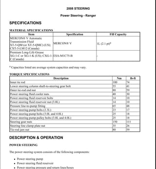
  • 1. 2008 STEERING Power Steering - Ranger SPECIFICATIONS MATERIAL SPECIFICATIONS a Capacities listed are average system capacities and may vary. TORQUE SPECIFICATIONS DESCRIPTION & OPERATION POWER STEERING The power steering system consists of the following components:  Power steering pump  Power steering fluid reservoir  Power steering pressure and return lines/hoses Item Specification Fill Capacity MERCON® V Automatic Transmission Fluid XT-5-QM (or XT-5-QMC) (US); CXT-5-LM12 (Canada) MERCON® V 1L (2.1 pt)a Premium Long-Life Grease XG-1-C or XG-1-K (US); CXG-1- C (Canada) ESA-M1C75-B - Description Nm lb-ft Inner tie rod 100 74 Lower steering column shaft-to-steering gear bolt 55 41 Outer tie-rod end nut 80 59 Power steering fluid cooler nuts 40 30 Power steering fluid reservoir bolts 14 10 Power steering fluid reservoir nut (3.0L) 14 10 Pressure line-to-pump fitting 65 48 Power steering pump bolts (2.3L) 23 17 Power steering pump bolts (3.0L and 4.0L) 25 18 Power steering pump pulley bolts (3.0L and 4.0L) 25 18 Steering gear nuts 150 111 Steering line clamp plate nut 35 26 Tie-rod jam nut 80 59 2008 Ford Ranger 2008 STEERING Power Steering - Ranger 2008 Ford Ranger 2008 STEERING Power Steering - Ranger Microsoft Wednesday, November 11, 2009 11:21:15 AM Page 1 © 2005 Mitchell Repair Information Company, LLC. Microsoft Wednesday, November 11, 2009 11:21:20 AM Page 1 © 2005 Mitchell Repair Information Company, LLC.
  • 2.  Power steering fluid cooler  Power steering gear  Inner tie rod The power steering system uses a vane-type pump to move the fluid from the reservoir to the steering gear and through the rest of the steering hydraulic system. The power steering pump is mounted to the engine and driven by the engine accessory drive belt. Power steering fluid flows into the pump from the reservoir. The power steering fluid is then trapped between the pump vanes and moved to the high-pressure side of the pump creating a flow of fluid. The restriction of this flow by the steering gear creates the pressure that provides the steering assist. A combined pressure relief/flow valve is built into the pump to control the maximum pressure and flow provided to the steering system. This action prevents damage to the system and provides the correct level of assist during all engine speeds. While under pressure, the power steering fluid flows through the high-pressure power steering line to the steering gear. The fluid exits the gear and flows through the return line, cooler and finally to the reservoir. The reservoir slows the fluid, allows air to escape and filters the fluid before returning it to the pump. DIAGNOSTIC TESTS POWER STEERING Refer to STEERING SYSTEM - GENERAL INFORMATION article. REMOVAL & INSTALLATION POWER STEERING FLUID RESERVOIR - 2.3L & 4.0L Material Item Specification MERCON® V Automatic Transmission Fluid XT-5-QM (or XT-5-QMC) (US); CXT-5-LM12 (Canada) MERCON® V 2008 Ford Ranger 2008 STEERING Power Steering - Ranger Microsoft Wednesday, November 11, 2009 11:21:15 AM Page 2 © 2005 Mitchell Repair Information Company, LLC.
  • 3. Fig. 1: Identifying Power Steering Fluid Reservoir - 2.3L With Torque Specifications Courtesy of FORD MOTOR CO. Item Part Number Description 1 W503924 Power steering fluid reservoir bolts (3 required) 2 3R700 Power steering fluid reservoir 3 3A713 Return hose 4 3659 Power steering pump supply hose 2008 Ford Ranger 2008 STEERING Power Steering - Ranger Microsoft Wednesday, November 11, 2009 11:21:15 AM Page 3 © 2005 Mitchell Repair Information Company, LLC.
  • 4. Fig. 2: Exploded View Of Power Steering Fluid Reservoir - 4.0L Engine With Torque Specifications Courtesy of FORD MOTOR CO. REMOVAL & INSTALLATION Item Part Number Description 1 3659 Power steering pump supply hose 2 3A005 Return hose 3 N606678 Power steering fluid reservoir bolts (2 required) 4 3R700 Power steering fluid reservoir CAUTION: While repairing the power steering system, care should be taken to prevent the entry of foreign material or failure of the power steering 2008 Ford Ranger 2008 STEERING Power Steering - Ranger Microsoft Wednesday, November 11, 2009 11:21:15 AM Page 4 © 2005 Mitchell Repair Information Company, LLC.
  • 5. All vehicles 1. Using a suitable suction device, remove the power steering fluid from the reservoir. 2. Compress the clamp and disconnect the return hose. 3. Compress the clamp and disconnect the power steering pump supply hose. 2.3L engines 4. Remove the 3 bolts and the power steering fluid reservoir.  To install, tighten to 14 Nm (10 lb-ft). 4.0L engines 5. Remove the 2 bolts and the power steering fluid reservoir.  To install, tighten to 14 Nm (10 lb-ft). All vehicles 6. To install, reverse the removal procedure. 7. Fill the power steering system. For additional information, refer to STEERING SYSTEM - GENERAL INFORMATION article. POWER STEERING FLUID RESERVOIR - 3.0L Material components may result. CAUTION: Do not allow power steering fluid to contact the engine accessory drive belt or the belt may be damaged. Item Specification MERCON® V Automatic Transmission Fluid XT-5-QM (or XT-5-QMC) (US); CXT-5-LM12 (Canada) MERCON® V 2008 Ford Ranger 2008 STEERING Power Steering - Ranger Microsoft Wednesday, November 11, 2009 11:21:15 AM Page 5 © 2005 Mitchell Repair Information Company, LLC.
  • 6. Fig. 3: Exploded View Of Power Steering Fluid Reservoir - 3.0L Engine With Torque Specifications Courtesy of FORD MOTOR CO. REMOVAL & INSTALLATION Item Part Number Description 1 W503923 Power steering fluid reservoir bolts (2 required) 2 W520101 Power steering fluid reservoir nut 3 3R700 Power steering fluid reservoir 4 CS7617 Power steering pump supply hose 5 3F731 Return hose CAUTION: While repairing the power steering system, care should be taken to 2008 Ford Ranger 2008 STEERING Power Steering - Ranger Microsoft Wednesday, November 11, 2009 11:21:15 AM Page 6 © 2005 Mitchell Repair Information Company, LLC.
  • 7. 1. Using a suitable suction device, remove the power steering fluid from the reservoir. 2. Compress the clamp and disconnect the return hose. 3. Compress the clamp and disconnect the power steering pump supply hose. 4. Remove the power steering fluid reservoir nut.  To install, tighten to 14 Nm (10 lb-ft). 5. Remove the 2 bolts and the power steering fluid reservoir.  To install, tighten to 14 Nm (10 lb-ft). 6. To install, reverse the removal procedure. 7. Fill the power steering system. For additional information, refer to STEERING SYSTEM - GENERAL INFORMATION article. POWER STEERING PUMP - 2.3L Special Tools Material prevent the entry of foreign material or failure of the power steering components may result. CAUTION: Do not allow power steering fluid to contact the engine accessory drive belt or the belt may be damaged. Illustration Tool Name Tool Number Installer Set, Teflon® Seal 211-D027 (D90P-3517-A) or equivalent Item Specification MERCON® V Automatic Transmission Fluid XT-5-QM (or XT-5-QMC) (US); CXT-5-LM12 (Canada) MERCON® V 2008 Ford Ranger 2008 STEERING Power Steering - Ranger Microsoft Wednesday, November 11, 2009 11:21:15 AM Page 7 © 2005 Mitchell Repair Information Company, LLC.
  • 8. Fig. 4: Identifying Power Steering Pump - 2.3L With Torque Specifications Courtesy of FORD MOTOR CO. REMOVAL & INSTALLATION 1. Using a suitable suction device, remove the power steering fluid from the reservoir. 2. Remove the power steering pump pulley. For additional information, refer to Power Steering Pump Pulley - 2.3L. 3. Compress the clamp and disconnect the power steering pump supply hose. Item Part Number Description 1 3A719 Pressure line-to-pump fitting 2 W705952 Power steering pump bolt (4 required) 3 C56697 Power steering pump supply hose 4 3A674 Power steering pump 5 N803257 Teflon® seal CAUTION: While repairing the power steering system, care should be taken to prevent the entry of foreign material or failure of the power steering components may result. CAUTION: Do not allow power steering fluid to contact the accessory drive belt or the belt may be damaged. 2008 Ford Ranger 2008 STEERING Power Steering - Ranger Microsoft Wednesday, November 11, 2009 11:21:15 AM Page 8 © 2005 Mitchell Repair Information Company, LLC.
  • 9. 4. Disconnect the pressure line-to-pump fitting.  Remove and discard the Teflon® seal.  To install, tighten to 65 Nm (48 lb-ft). 5. Remove the 4 power steering pump bolts and the power steering pump.  To install, tighten to 23 Nm (17 lb-ft). 6. To install, reverse the removal procedure.  Using the special tool, install a new Teflon® seal on the pressure line-to-pump fitting.  Fill the power steering system. For additional information, refer to STEERING SYSTEM - GENERAL INFORMATION article. Fig. 5: Installing Teflon(R) Seal Using Special Tool Courtesy of FORD MOTOR CO. POWER STEERING PUMP - 3.0L Special Tools Material CAUTION: A new Teflon® seal must be installed any time the pressure line fitting is disconnected from the power steering pump or a fluid leak may occur. Illustration Tool Name Tool Number Installer Set, Teflon® Seal 211-D027 (D90P-3517-A) or equivalent Item Specification MERCON® V Automatic Transmission Fluid XT-5-QM (or XT-5-QMC) (US); CXT-5-LM12 (Canada) MERCON® V 2008 Ford Ranger 2008 STEERING Power Steering - Ranger Microsoft Wednesday, November 11, 2009 11:21:15 AM Page 9 © 2005 Mitchell Repair Information Company, LLC.
  • 10. Fig. 6: Exploded View Of Power Steering Pump - 3.0L Engine With Torque Specifications Courtesy of FORD MOTOR CO. REMOVAL & INSTALLATION 1. Using a suitable suction device, remove the power steering fluid from the reservoir. 2. Remove the power steering pump pulley. For additional information, refer to Power Steering Pump Pulley - 3.0L, 4.0L. 3. Disconnect the pressure line-to-pump fitting. Item Part Number Description 1 N605784 Power steering pump bolt (3 required) 2 3R700 Power steering fluid reservoir 3 CS7617 Power steering pump supply hose 4 3A674 Power steering pump 5 N803257 Teflon® seal 6 3A719 Pressure line-to-pump fitting CAUTION: While repairing the power steering system, care should be taken to prevent the entry of foreign material or failure of the power steering components may result. CAUTION: Do not allow power steering fluid to contact the engine accessory drive belt or the belt may be damaged. 2008 Ford Ranger 2008 STEERING Power Steering - Ranger Microsoft Wednesday, November 11, 2009 11:21:16 AM Page 10 © 2005 Mitchell Repair Information Company, LLC.
  • 11.  Remove and discard the Teflon® seal.  To install, tighten to 65 Nm (48 lb-ft). 4. Compress the clamp and disconnect the power steering pump supply hose. 5. Remove the 3 bolts and the power steering pump.  To install, tighten to 25 Nm (18 lb-ft). 6. To install, reverse the removal procedure.  Using the special tool, install a new Teflon® seal on the pressure line-to-pump fitting.  Fill the power steering system. For additional information, refer to STEERING SYSTEM - GENERAL INFORMATION article. Fig. 7: Installing Teflon(R) Seal Using Special Tool Courtesy of FORD MOTOR CO. POWER STEERING PUMP - 4.0L Special Tools Material CAUTION: A new Teflon® seal must be installed any time the pressure line fitting is disconnected from the power steering pump or a fluid leak may occur. Illustration Tool Name Tool Number Installer Set, Teflon® Seal 211-D027 (D90P-3517-A) or equivalent Item Specification MERCON® V Automatic Transmission Fluid XT-5-QM (or XT-5-QMC) (US); CXT-5-LM12 (Canada) MERCON® V 2008 Ford Ranger 2008 STEERING Power Steering - Ranger Microsoft Wednesday, November 11, 2009 11:21:16 AM Page 11 © 2005 Mitchell Repair Information Company, LLC.
  • 12. Fig. 8: Exploded View Of Power Steering Pump - 4.0L With Torque Specifications Courtesy of FORD MOTOR CO. REMOVAL & INSTALLATION 1. Using a suitable suction device, remove the power steering fluid from the reservoir. 2. Remove the engine cooling fan. For additional information, refer to ENGINE COOLING article. 3. Remove the power steering pump pulley. For additional information, refer to Power Steering Pump Pulley - 3.0L, 4.0L. Item Part Number Description 1 3A719 Pressure line-to-pump fitting 2 3659 Power steering pump supply hose 3 W700839 Power steering pump bolt (3 required) 4 3A674 Power steering pump 5 N803257 Teflon® seal CAUTION: While repairing the power steering system, care should be taken to prevent the entry of foreign material or failure of the power steering components may result. CAUTION: Do not allow power steering fluid to contact the accessory drive belt or the belt may be damaged. 2008 Ford Ranger 2008 STEERING Power Steering - Ranger Microsoft Wednesday, November 11, 2009 11:21:16 AM Page 12 © 2005 Mitchell Repair Information Company, LLC.
  • 13. 4. Compress the clamp and disconnect the power steering pump supply hose from the power steering fluid reservoir. 5. Disconnect the pressure line-to-pump fitting.  To install, tighten to 65 Nm (48 lb-ft). 6. Compress the clamp and disconnect the power steering pump supply hose from the power steering pump. 7. Remove the 3 bolts and the power steering pump.  Tighten to 25 Nm (18 lb-ft). 8. To install, reverse removal procedure.  Using the special tool, install a new Teflon® seal on the pressure line-to-pump fitting.  Fill the power steering system. For additional information, refer to STEERING SYSTEM - GENERAL INFORMATION article. Fig. 9: Installing Teflon(R) Seal Using Special Tool Courtesy of FORD MOTOR CO. POWER STEERING PUMP PULLEY - 2.3L Special Tools CAUTION: A new Teflon® seal must be installed any time the pressure line is disconnected from the power steering pump or a fluid leak may occur. Illustration Tool Name Tool Number Remover, Power Steering Pump Pulley 211-016 (T69L-10300-B) Installer, Power Steering Pump Pulley 211-185 (T91P-3A733-A) 2008 Ford Ranger 2008 STEERING Power Steering - Ranger Microsoft Wednesday, November 11, 2009 11:21:16 AM Page 13 © 2005 Mitchell Repair Information Company, LLC.
  • 14. Fig. 10: Identifying Power Steering Pump Pulley - 2.3L Courtesy of FORD MOTOR CO. REMOVAL 1. Remove the air cleaner outlet pipe. For additional information, refer to INTAKE AIR DISTRIBUTION & FILTERING article. 2. Rotate the accessory drive belt tensioner counterclockwise and position the accessory drive belt aside. Item Part Number Description 1 3D673 Power steering pump pulley 2 8620 Accessory drive belt 2008 Ford Ranger 2008 STEERING Power Steering - Ranger Microsoft Wednesday, November 11, 2009 11:21:16 AM Page 14 © 2005 Mitchell Repair Information Company, LLC.
  • 15. Fig. 11: Locating Accessory Drive Belt Tensioner Courtesy of FORD MOTOR CO. 3. Using the special tool, remove the power steering pump pulley. Fig. 12: Removing Pulley Using Special Tool (211-016) Courtesy of FORD MOTOR CO. INSTALLATION 1. Using the special tool, install the power steering pump pulley. CAUTION: Do not install a power steering pump pulley that has been removed and installed twice or pulley failure and/or pump damage may occur. Inspect the pulley for paint marks in the web area near the hub. If there are 2 paint marks, discard the pulley and install a new one. If there is 1 paint mark or no paint marks, use a paint pencil to mark the web area of the pulley near the hub. 2008 Ford Ranger 2008 STEERING Power Steering - Ranger Microsoft Wednesday, November 11, 2009 11:21:16 AM Page 15 © 2005 Mitchell Repair Information Company, LLC.
  • 16. Fig. 13: Installing Pulley Using Special Tool (211-185) Courtesy of FORD MOTOR CO. 2. Rotate the tensioner counterclockwise and position the belt on the power steering pump pulley. Fig. 14: Locating Accessory Drive Belt Tensioner Courtesy of FORD MOTOR CO. 3. Install the air cleaner outlet pipe. For additional information, refer to INTAKE AIR DISTRIBUTION & FILTERING article. POWER STEERING PUMP PULLEY - 3.0L, 4.0L NOTE: For additional information on accessory drive belt routing, refer to ACCESSORY DRIVE article. 2008 Ford Ranger 2008 STEERING Power Steering - Ranger Microsoft Wednesday, November 11, 2009 11:21:16 AM Page 16 © 2005 Mitchell Repair Information Company, LLC.
  • 17. Fig. 15: Identifying Power Steering Pump Pulley - 3.0L, 4.0L With Torque Specifications Courtesy of FORD MOTOR CO. REMOVAL & INSTALLATION 1. Loosen the power steering pump pulley bolts. 2. Rotate the accessory drive belt tensioner counterclockwise and position the accessory drive belt aside. 3. Remove the 3 bolts and the power steering pump pulley.  To install, tighten to 25 Nm (18 lb-ft). 4. To install, reverse the removal procedure. INNER TIE ROD Item Part Number Description 1 N605784 Power steering pump pulley bolts (3 required) 2 3A733 Power steering pump pulley 3 8620 Accessory drive belt NOTE: 4.0L engine shown in illustration, 3.0L engine similar. NOTE: For additional information on accessory drive belt routing, refer to ACCESSORY DRIVE article. 2008 Ford Ranger 2008 STEERING Power Steering - Ranger Microsoft Wednesday, November 11, 2009 11:21:16 AM Page 17 © 2005 Mitchell Repair Information Company, LLC.
  • 18. Special Tools Material Fig. 16: Identifying Inner Tie Rod With Torque Specifications Courtesy of FORD MOTOR CO. Illustration Tool Name Tool Number Inner Tie-Rod Socket Tool 211-D029 or equivalent Tie-Rod End Separator 211-105 (T85M-3395-A) or equivalent Item Specification Premium Long-Life Grease XG-1-C or XG-1-K (US); CXG-1-C (Canada) ESA-M1C75-B Item Part Number Description 1 N803637 Tie-rod jam nut (part of 3280) (2 required) 2008 Ford Ranger 2008 STEERING Power Steering - Ranger Microsoft Wednesday, November 11, 2009 11:21:16 AM Page 18 © 2005 Mitchell Repair Information Company, LLC.
  • 19. REMOVAL & INSTALLATION Coil spring suspension vehicles 1. Remove the wheel and tire. For additional information, refer to WHEELS & TIRES article. 2. Loosen the tie-rod jam nuts.  To install, tighten to 80 Nm (59 lb-ft). 3. Remove the outer tie-rod end cotter pin and nut.  Discard the cotter pin.  To install, tighten to 80 Nm (59 lb-ft). 4. Using the special tool, disconnect the outer tie-rod end. 2 N800895 Outer tie-rod end nut (2 required) 3 3290 Outer tie-rod end (2 required) 4 3K745 Outer bellows boot clamp (2 required) 5 3C650A Inner bellows boot clamp (2 required) 6 3K661 Steering gear bellows boot (2 required) 7 3280 Inner tie rod (2 required) 8 N642569 Cotter pin (2 required) CAUTION: The boots and clamps are designed to provide an airtight seal and protect the internal components of the steering gear. If the seal is not airtight, the vacuum generated during turning may draw water and foreign material into the gear and damage internal components. Zip ties do not produce an airtight seal and must not be used. CAUTION: The inner ball joint grease is not compatible with water. Water and foreign material trapped in the grease may damage the joint. CAUTION: If present, the orientation of the vent tubes must be noted so the boots and vent tubes may be installed in their original locations. Incorrect venting may lead to internal component damage. CAUTION: Do not damage the tie-rod end boot when installing the special tool. 2008 Ford Ranger 2008 STEERING Power Steering - Ranger Microsoft Wednesday, November 11, 2009 11:21:16 AM Page 19 © 2005 Mitchell Repair Information Company, LLC.
  • 20. Fig. 17: Identifying Special Tool On Tie-Rod End Courtesy of FORD MOTOR CO. 5. Remove the outer tie-rod end. 6. Remove the tie-rod jam nut. 7. Remove the inner and outer bellows boot clamps. 8. Remove the bellows boot. 9. Using the special tool, remove the inner tie rod.  To install, tighten to 100 Nm (74 lb-ft). NOTE: Count and record the number of times the outer tie-rod end turns for assembly reference. NOTE: If repairing the RH side, it will be necessary to pull back the LH inner bellows boot to hold the steering gear. CAUTION: Place the steering gear at the center position. Use a 21 mm (0.82 in) crowfoot on the flat of the rack gear to resist rotation and to prevent damage during removal and installation of the inner tie rod. NOTE: The help of an assistant may be needed for removal of the RH inner tie rod. 2008 Ford Ranger 2008 STEERING Power Steering - Ranger Microsoft Wednesday, November 11, 2009 11:21:16 AM Page 20 © 2005 Mitchell Repair Information Company, LLC.
  • 21. Fig. 18: Inner Tie Rod And Special Tool Courtesy of FORD MOTOR CO. Torsion bar suspension vehicles 10. Loosen the tie-rod jam nut.  To install, tighten to 80 Nm (59 lb-ft). 11. Remove the steering gear. For additional information, refer to Steering Gear - Rear Wheel Drive (RWD) or Steering Gear - Four Wheel Drive (4WD). 12. Remove the outer tie-rod end and jam nut. 13. Remove the inner and outer bellows boot clamps. 14. Using the special tool, remove the inner tie rod.  To install, tighten to 100 Nm (74 lb-ft). Fig. 19: Locating Inner Tie Rod Courtesy of FORD MOTOR CO. All vehicles NOTE: Count and record the number of times the outer tie-rod end turns for assembly reference. NOTE: If repairing the RH side, it will be necessary to pull back the LH inner bellows boot to hold the steering gear. CAUTION: Place the steering gear at the center position. Use a 21 mm (0.82 in) crowfoot on the flat of the rack gear to resist rotation and to prevent damage during removal and installation of the inner tie rod. NOTE: The help of an assistant may be needed for removal of the RH inner tie rod. 2008 Ford Ranger 2008 STEERING Power Steering - Ranger Microsoft Wednesday, November 11, 2009 11:21:16 AM Page 21 © 2005 Mitchell Repair Information Company, LLC.
  • 22. 15. Thoroughly clean and inspect all the parts to be reused. Install new parts as necessary. 16. Check that the bellows boot seal is positioned correctly over the steering gear housing bead at the large inside diameter (ID) and is in the inner tie-rod groove at the small ID.  Check that the bellows boot seal is not twisted and the breather tube is securely inserted into the breather nipple at both bellows boots. 17. To install, reverse the removal procedure. 18. Check and if necessary adjust the front toe. For additional information, refer to SUSPENSION SYSTEM - GENERAL INFORMATION article. POWER STEERING FLUID COOLER Material CAUTION: Thoroughly remove any dirt or foreign material that is present. This material is extremely harmful to the steering gear. NOTE: Lubricate the inner tie rod inside groove with steering gear grease where the bellows boot is clamped. Item Specification MERCON® V Automatic Transmission Fluid XT-5-QM (or XT-5-QMC) (US); CXT-5-LM12 (Canada) MERCON® V 2008 Ford Ranger 2008 STEERING Power Steering - Ranger Microsoft Wednesday, November 11, 2009 11:21:16 AM Page 22 © 2005 Mitchell Repair Information Company, LLC.
  • 23. Fig. 20: Identifying Power Steering Fluid Cooler With Torque Specifications Courtesy of FORD MOTOR CO. REMOVAL & INSTALLATION 1. With the vehicle in NEUTRAL, position it on a hoist. For additional information, refer to JACKING & LIFTING article. 2. Remove the 2 power steering fluid cooler nuts.  To install, tighten to 40 Nm (30 lb-ft). 3. Compress the clamps and disconnect the 2 power steering fluid cooler hoses. 4. To install, reverse the removal procedure.  Fill the power steering system. For additional information, refer to STEERING SYSTEM - GENERAL INFORMATION article. STEERING GEAR - REAR WHEEL DRIVE (RWD) Special Tools Item Part Number Description 1 3A713B Power steering fluid cooler hose 2 3A713A Power steering fluid cooler hose 3 N800169 Power steering fluid cooler nuts (2 required) 4 3F780 Power steering fluid cooler CAUTION: While repairing the power steering system, care should be taken to prevent the entry of foreign material or failure of the power steering components may result. Illustration Tool Name Tool Number Remover, Tie-Rod End 211-001 (TOOL-3290-D) or equivalent 2008 Ford Ranger 2008 STEERING Power Steering - Ranger Microsoft Wednesday, November 11, 2009 11:21:16 AM Page 23 © 2005 Mitchell Repair Information Company, LLC.
  • 24. Fig. 21: Identifying Steering Gear - Rear Wheel Drive (RWD) With Torque Specifications Courtesy of FORD MOTOR CO. Item Part Number Description 1 W520413 Steering line clamp plate nut 2 3A713 Return line 3 3A719 Pressure line 4 N803256 O-ring seal 5 N803257 O-ring seal 6 N811762 Steering gear studs (2 required) 7 N803942 Lower steering column shaft-to-steering gear bolt 8 3504 Steering gear 9 N808265 Steering gear nuts (2 required) 2008 Ford Ranger 2008 STEERING Power Steering - Ranger Microsoft Wednesday, November 11, 2009 11:21:16 AM Page 24 © 2005 Mitchell Repair Information Company, LLC.
  • 25. REMOVAL & INSTALLATION All vehicles 1. Remove the front wheels and tires. For additional information, refer to WHEELS & TIRES article. 2. Place the steering wheel in the straight-ahead position and remove the ignition key.  Rotate the steering wheel until the steering column locks into position. 3.0L and 4.0L engines 3. Remove the power steering fluid cooler. For additional information, refer to Power Steering Fluid Cooler. All vehicles 4. Remove the outer tie-rod end cotter pins and nuts.  Discard the cotter pins.  To install, tighten to 80 Nm (59 lb-ft). 5. Using special tool, separate the outer tie-rod ends from the wheel spindles. 10 N642569 Cotter pin (2 required) 11 N800895 Outer tie-rod end nut (2 required) CAUTION: When repairing the power steering system, care should be taken to prevent the entry of foreign material or failure of the power steering components may result. CAUTION: Do not damage the tie-rod boot when installing the special tool. NOTE: Remove the adapter from the ball end of the special tool. Apply a small amount of grease to the tie-rod end stud and the ball of the special tool. 2008 Ford Ranger 2008 STEERING Power Steering - Ranger Microsoft Wednesday, November 11, 2009 11:21:16 AM Page 25 © 2005 Mitchell Repair Information Company, LLC.
  • 26. Fig. 22: Separating Outer Tie Rods From Wheel Knuckles Courtesy of FORD MOTOR CO. 6. Remove the lower steering column shaft-to-steering gear bolt and disconnect the lower steering column shaft from the gear.  Discard the bolt.  To install, tighten to 55 Nm (41 lb-ft). 7. Remove the steering line clamp plate nut and disconnect the pressure and return lines.  Discard the O-ring seals.  To install, tighten to 35 Nm (26 lb-ft). 8. Plug or cap the return line, pressure line and the steering gear ports to prevent the entry of dirt. 9. Remove the 2 steering gear nuts and the 2 steering gear studs.  To install, tighten to 150 Nm (111 lb-ft). 10. Remove the steering gear. 11. If necessary, remove the outer tie-rod ends. 12. To install, reverse the removal procedure.  Install new power steering line O-ring seals. 13. Fill the power steering system. For additional information, refer to STEERING SYSTEM - GENERAL INFORMATION article. 14. Check and, if necessary, adjust the front toe. STEERING GEAR - FOUR WHEEL DRIVE (4WD) Special Tools CAUTION: Do not allow the steering column to rotate while the steering column shaft is disconnected from the steering gear or damage to the clockspring may result. If there is evidence that the steering column has rotated, the clockspring must be removed and recentered. For additional information, refer to SUPPLEMENTAL RESTRAINT SYSTEM article. CAUTION: Hold the tops of the steering gear studs to avoid damaging the steering gear fluid transfer tubes. CAUTION: New O-ring seals must be installed any time the power steering lines are disconnected from the steering gear or a fluid leak may occur. Illustration Tool Name Tool Number 2008 Ford Ranger 2008 STEERING Power Steering - Ranger Microsoft Wednesday, November 11, 2009 11:21:16 AM Page 26 © 2005 Mitchell Repair Information Company, LLC.
  • 27. Fig. 23: Identifying Steering Gear - Four Wheel Drive (4WD) With Torque Specifications Courtesy of FORD MOTOR CO. Remover, Tie-Rod End 211-001 (TOOL-3290-D) or equivalent Item Part Number Description 1 W520413 Steering line clamp plate nut 2 3A713 Return line 3 3A719 Pressure line 4 N803256 O-ring seal 2008 Ford Ranger 2008 STEERING Power Steering - Ranger Microsoft Wednesday, November 11, 2009 11:21:16 AM Page 27 © 2005 Mitchell Repair Information Company, LLC.
  • 28. REMOVAL All vehicles 1. Remove the front wheels and tires. For additional information, refer to WHEELS & TIRES article. 2. Place the steering wheel in the straight-ahead position and remove the ignition key.  Rotate the steering wheel until the steering column locks into position. 3.0L and 4.0L engines 3. Remove the power steering fluid cooler. For additional information, refer to Power Steering Fluid Cooler. All vehicles 4. Loosen the tie-rod jam nuts. 5. Remove the outer tie-rod end cotter pins and nuts.  Discard the cotter pins. 6. Using the special tool, separate the outer tie-rod ends from the wheel knuckles. 5 N803257 O-ring seal 6 N811762 Steering gear studs (2 required) 7 N803942 Lower steering column shaft-to-steering gear bolt 8 3504 Steering gear 9 N803637 Tie rod jam nut (part of 3280) (2 required) 10 N808265 Steering gear nuts (2 required) 11 3290 Outer tie-rod end (2 required) 12 N642569 Cotter pin (2 required) 13 N800895 Outer tie-rod end nut (2 required) CAUTION: When repairing the power steering system, care should be taken to prevent the entry of foreign material or failure of the power steering components may result. CAUTION: Do not damage the tie-rod boot when installing the special tool. NOTE: Remove the adapter from the ball end of the special tool. Apply a small amount of grease to the tie-rod end stud and the ball of the special tool. 2008 Ford Ranger 2008 STEERING Power Steering - Ranger Microsoft Wednesday, November 11, 2009 11:21:16 AM Page 28 © 2005 Mitchell Repair Information Company, LLC.
  • 29. Fig. 24: Separating Outer Tie Rods From Wheel Knuckles Courtesy of FORD MOTOR CO. 7. Remove the outer tie-rod ends.  Count and record the number of turns required to remove the outer tie-rod end. 8. Remove the stabilizer bar and link. For additional information, refer to FRONT SUSPENSION - FOUR WHEEL DRIVE (4WD) article. 9. Remove the lower steering column shaft-to-steering gear bolt and disconnect the shaft from the steering gear.  Discard the bolt. 10. Remove the steering line clamp plate nut and disconnect the pressure and return lines.  Discard the O-ring seals. 11. Remove the 2 steering gear nuts and steering gear studs. 12. Rotate the steering gear control valve housing toward the front of the vehicle. CAUTION: Do not allow the steering column to rotate while the steering column shaft is disconnected from the steering gear or damage to the clockspring may result. If there is evidence that the steering column has rotated, the clockspring must be removed and recentered. For additional information, refer to SUPPLEMENTAL RESTRAINT SYSTEM article. CAUTION: Hold the tops of the steering gear studs to avoid damaging the steering gear fluid transfer tubes. 2008 Ford Ranger 2008 STEERING Power Steering - Ranger Microsoft Wednesday, November 11, 2009 11:21:16 AM Page 29 © 2005 Mitchell Repair Information Company, LLC.
  • 30. Fig. 25: Rotating Steering Gear Control Valve Housing Toward Front Of Vehicle Courtesy of FORD MOTOR CO. 13. Turn the steering gear input shaft to the right until the stop is reached. 14. Move the steering gear as far to the RH side of the vehicle as possible. Fig. 26: Moving Steering Gear As Far To RH Side Of Vehicle As Possible Courtesy of FORD MOTOR CO. 15. Move the LH inner tie rod forward to clear the frame crossmember. Fig. 27: Locating LH Inner Tie Rod Courtesy of FORD MOTOR CO. 16. Remove the steering gear. 2008 Ford Ranger 2008 STEERING Power Steering - Ranger Microsoft Wednesday, November 11, 2009 11:21:16 AM Page 30 © 2005 Mitchell Repair Information Company, LLC.
  • 31. Fig. 28: Removing Steering Gear Courtesy of FORD MOTOR CO. INSTALLATION All vehicles 1. Turn the steering gear input shaft to the right until the stop is reached. Count and record the number of turns required. 2. Install the steering gear into the RH opening of the crossmember. Fig. 29: Installing Steering Gear Into RH Opening Of Crossmember Courtesy of FORD MOTOR CO. CAUTION: Handle the steering gear with caution to avoid damage to fluid transfer tubes and to avoid dimples in the steering gear bellows boot. NOTE: Make sure the steering gear input shaft is turned to the left until the stop is reached. NOTE: Make sure the steering gear control valve housing is turned toward the front of the vehicle. CAUTION: Take care not to scuff or tear the steering gear bellows boots. 2008 Ford Ranger 2008 STEERING Power Steering - Ranger Microsoft Wednesday, November 11, 2009 11:21:16 AM Page 31 © 2005 Mitchell Repair Information Company, LLC.
  • 32. 3. Move the steering gear as far to the RH side of the vehicle as possible. Fig. 30: Moving Steering Gear As Far To RH Side Of Vehicle As Possible Courtesy of FORD MOTOR CO. 4. Move the LH inner tie rod into the opening in the crossmember and move the steering gear into position. Fig. 31: Locating LH Inner Tie Rod Courtesy of FORD MOTOR CO. 5. To place the steering gear in the straight-ahead position, turn the steering gear input shaft to the left by 1/2 the number of turns previously recorded. 6. Rotate the steering gear control valve housing toward the rear of the vehicle. Fig. 32: Rotating Steering Gear Control Valve Housing Toward Rear Of Vehicle Courtesy of FORD MOTOR CO. 7. Install the 2 steering gear studs. 2008 Ford Ranger 2008 STEERING Power Steering - Ranger Microsoft Wednesday, November 11, 2009 11:21:16 AM Page 32 © 2005 Mitchell Repair Information Company, LLC.
  • 33. 8. Install the 2 steering gear nuts.  Tighten to 150 Nm (111 lb-ft). 9. Position the pressure and return lines and install the steering line clamp plate nut.  Tighten to 35 Nm (26 lb-ft). 10. Connect the steering column shaft to the steering gear and install a new bolt.  Tighten to 55 Nm (41 lb-ft). 11. Install the stabilizer bar and link. For additional information, refer to FRONT SUSPENSION - FOUR WHEEL DRIVE (4WD) article. 12. Install the outer tie-rod ends.  Rotate the outer tie-rod ends the number of turns recorded during removal. 13. Position the outer tie-rod ends and install the nuts and new cotter pins.  Check that the brake disc shields are not bent and are not in contact with the outer tie-rod end boots.  Tighten to 80 Nm (59 lb-ft). 3.0L and 4.0L engines 14. Install the power steering fluid cooler. For additional information, refer to Power Steering Fluid Cooler. All vehicles 15. Tighten the tie-rod jam nuts.  Tighten to 80 Nm (59 lb-ft). 16. Fill the power steering system. For additional information, refer to STEERING SYSTEM - GENERAL INFORMATION article. 17. Check and, if necessary, adjust the front toe. For additional information, refer to SUSPENSION SYSTEM - GENERAL INFORMATION article. CAUTION: Hold the tops of the steering gear studs to avoid damaging the steering gear fluid transfer tubes. CAUTION: New O-rings must be installed any time the lines are disconnected from the steering gear or a fluid leak may occur. CAUTION: Do not allow the steering column to rotate while the steering column shaft is disconnected from the steering gear or damage to the clockspring may result. If there is evidence that the steering column has rotated, the clockspring must be removed and re-centered. For additional information, refer to SUPPLEMENTAL RESTRAINT SYSTEM article. 2008 Ford Ranger 2008 STEERING Power Steering - Ranger Microsoft Wednesday, November 11, 2009 11:21:16 AM Page 33 © 2005 Mitchell Repair Information Company, LLC.
  • 34. Thank you very much for your reading. Please Click Here Then Get More Information.