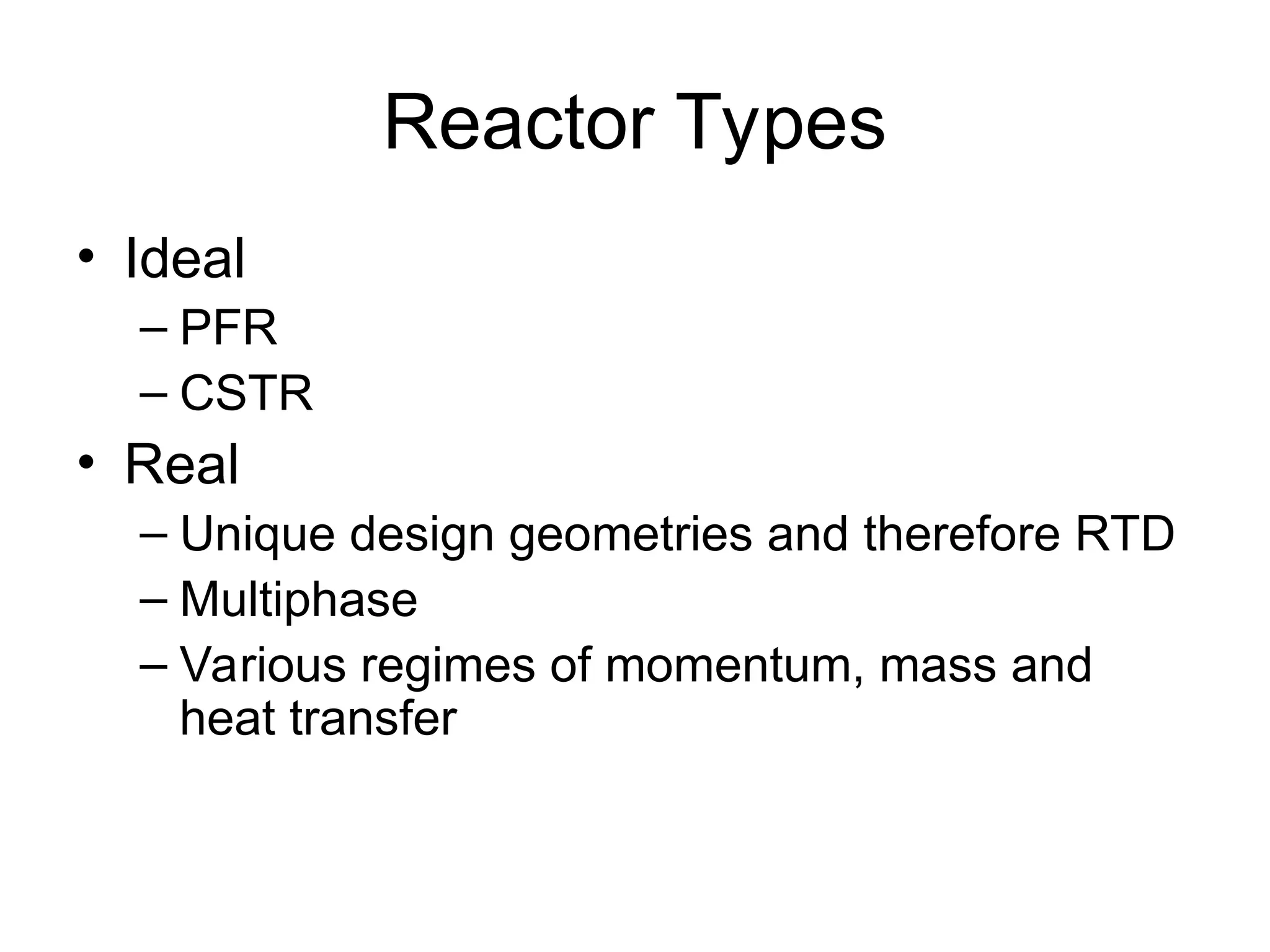
Reactor Types
• Ideal
–PFR
– CSTR
• Real
– Unique design geometries and therefore RTD
– Multiphase
– Various regimes of momentum, mass and
heat transfer
3.
Reactor Cost
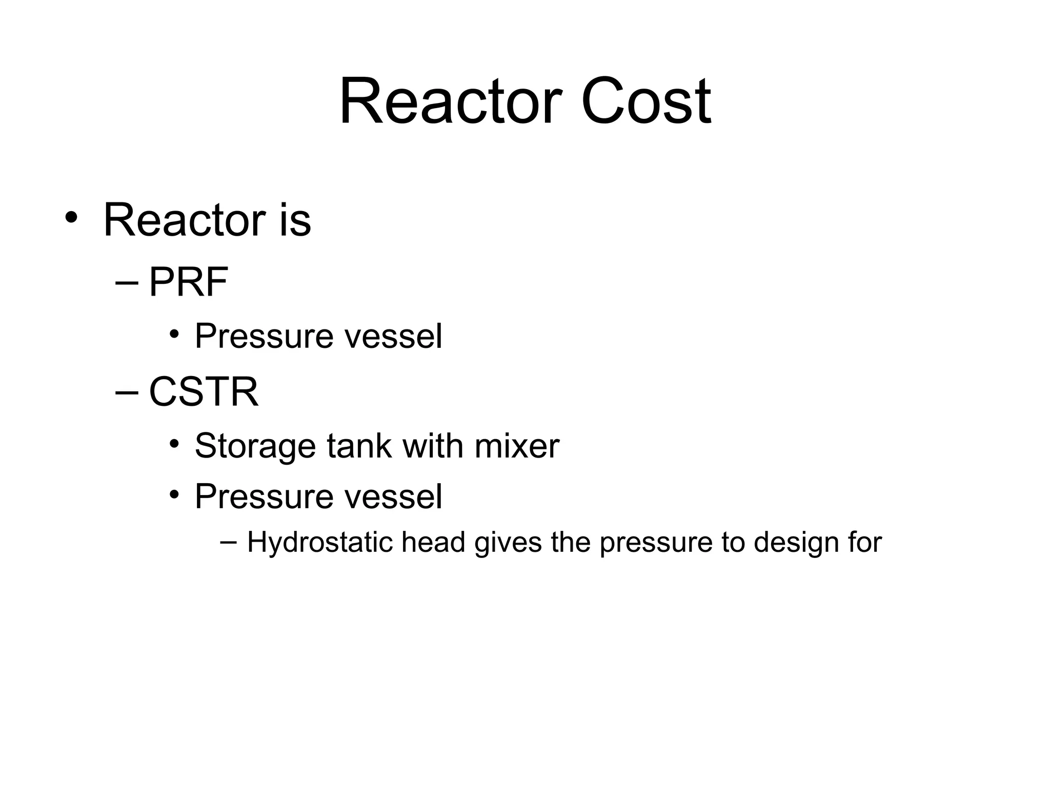
• Reactoris
– PRF
• Pressure vessel
– CSTR
• Storage tank with mixer
• Pressure vessel
– Hydrostatic head gives the pressure to design for
4.
Reactor Cost
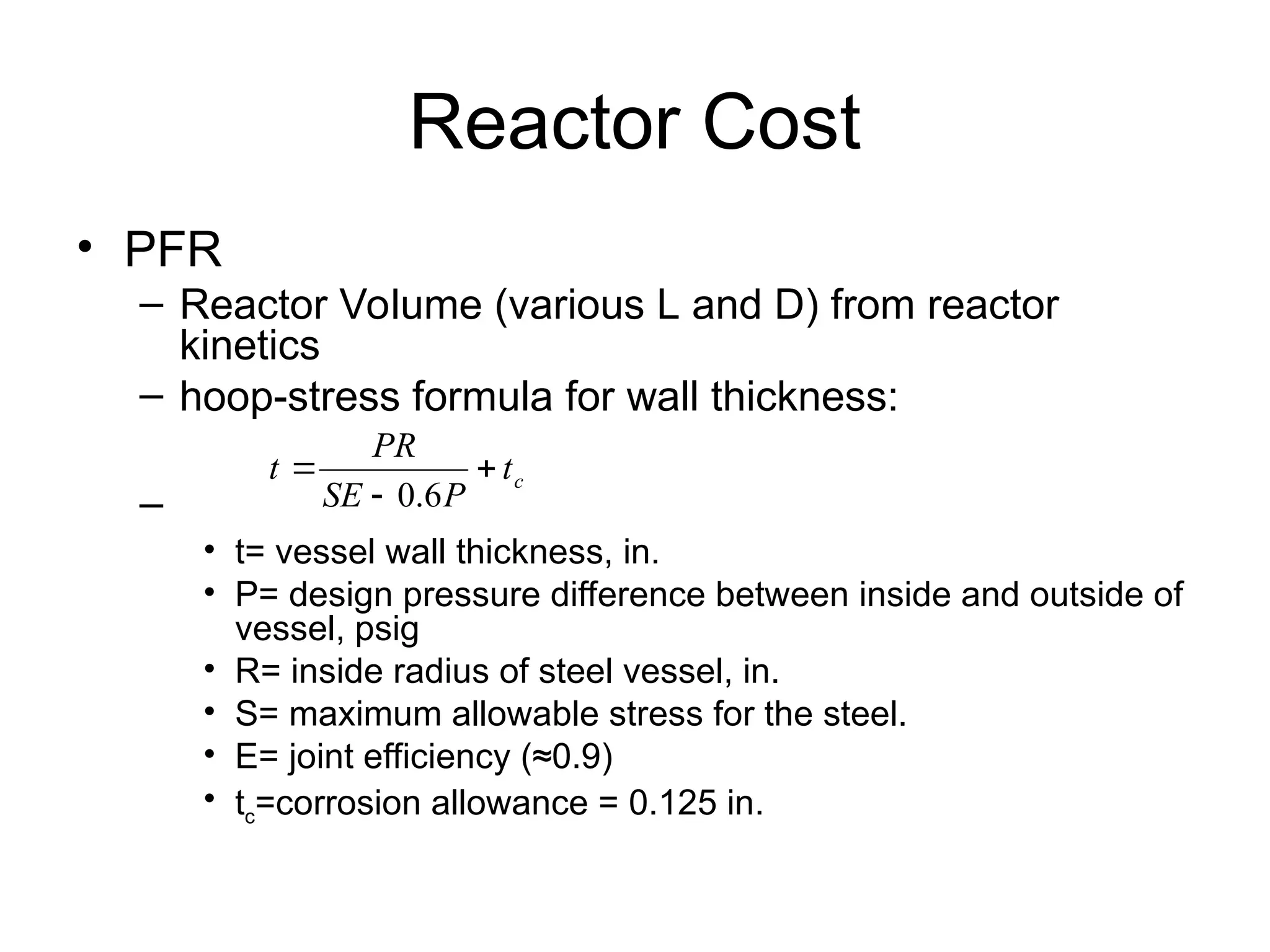
• PFR
–Reactor Volume (various L and D) from reactor
kinetics
– hoop-stress formula for wall thickness:
–
• t= vessel wall thickness, in.
• P= design pressure difference between inside and outside of
vessel, psig
• R= inside radius of steel vessel, in.
• S= maximum allowable stress for the steel.
• E= joint efficiency (≈0.9)
• tc=corrosion allowance = 0.125 in.
c
t
P
SE
PR
t
6
.
0
5.
Reactor Cost
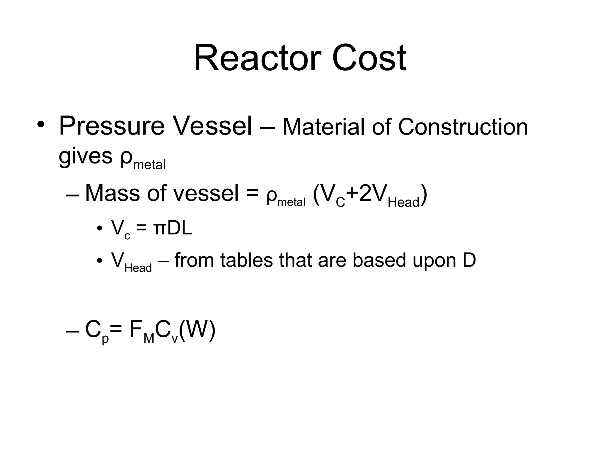
• PressureVessel – Material of Construction
gives ρmetal
– Mass of vessel = ρmetal (VC+2VHead)
• Vc = πDL
• VHead – from tables that are based upon D
– Cp= FMCv(W)
6.
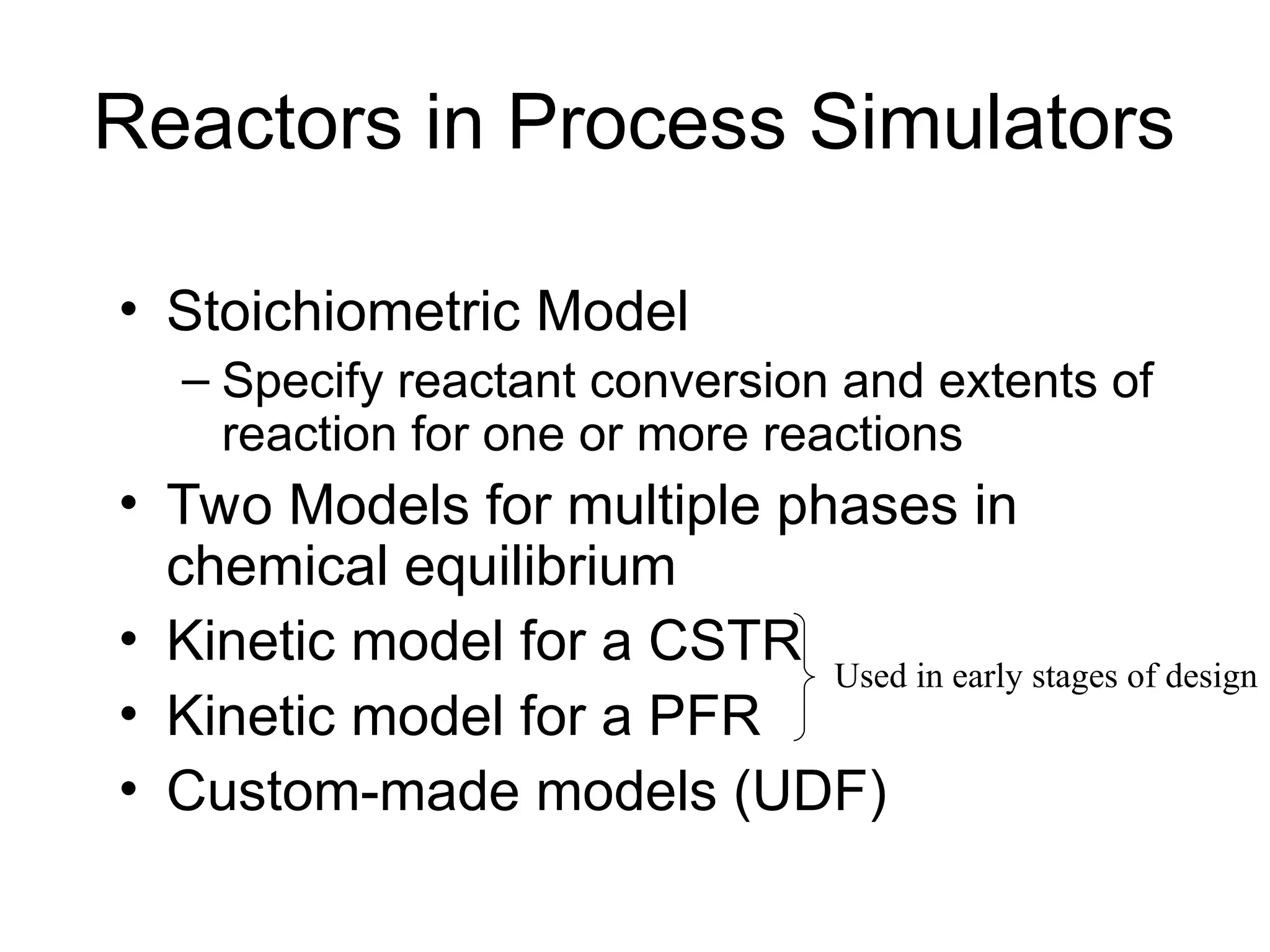
Reactors in ProcessSimulators
• Stoichiometric Model
– Specify reactant conversion and extents of
reaction for one or more reactions
• Two Models for multiple phases in
chemical equilibrium
• Kinetic model for a CSTR
• Kinetic model for a PFR
• Custom-made models (UDF)
Used in early stages of design
7.
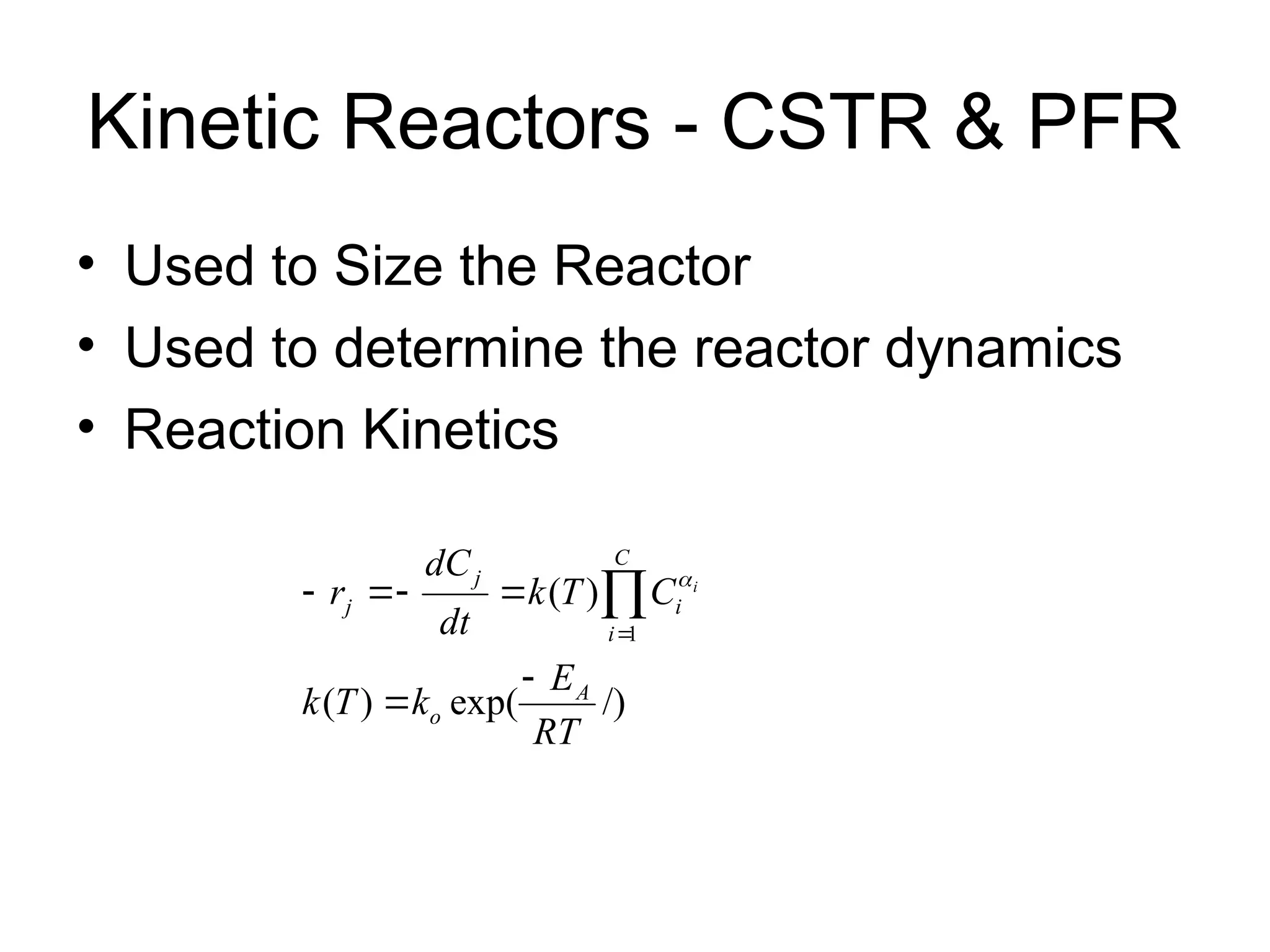
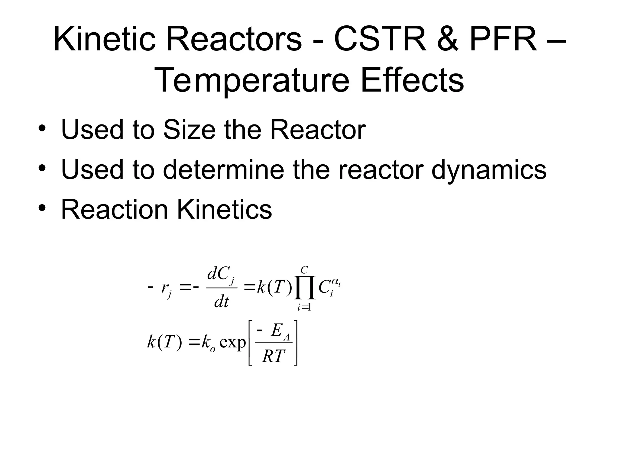
Kinetic Reactors -CSTR & PFR
• Used to Size the Reactor
• Used to determine the reactor dynamics
• Reaction Kinetics
/)
exp(
)
(
)
(
1
RT
E
k
T
k
C
T
k
dt
dC
r
A
o
C
i
i
j
j
i
8.
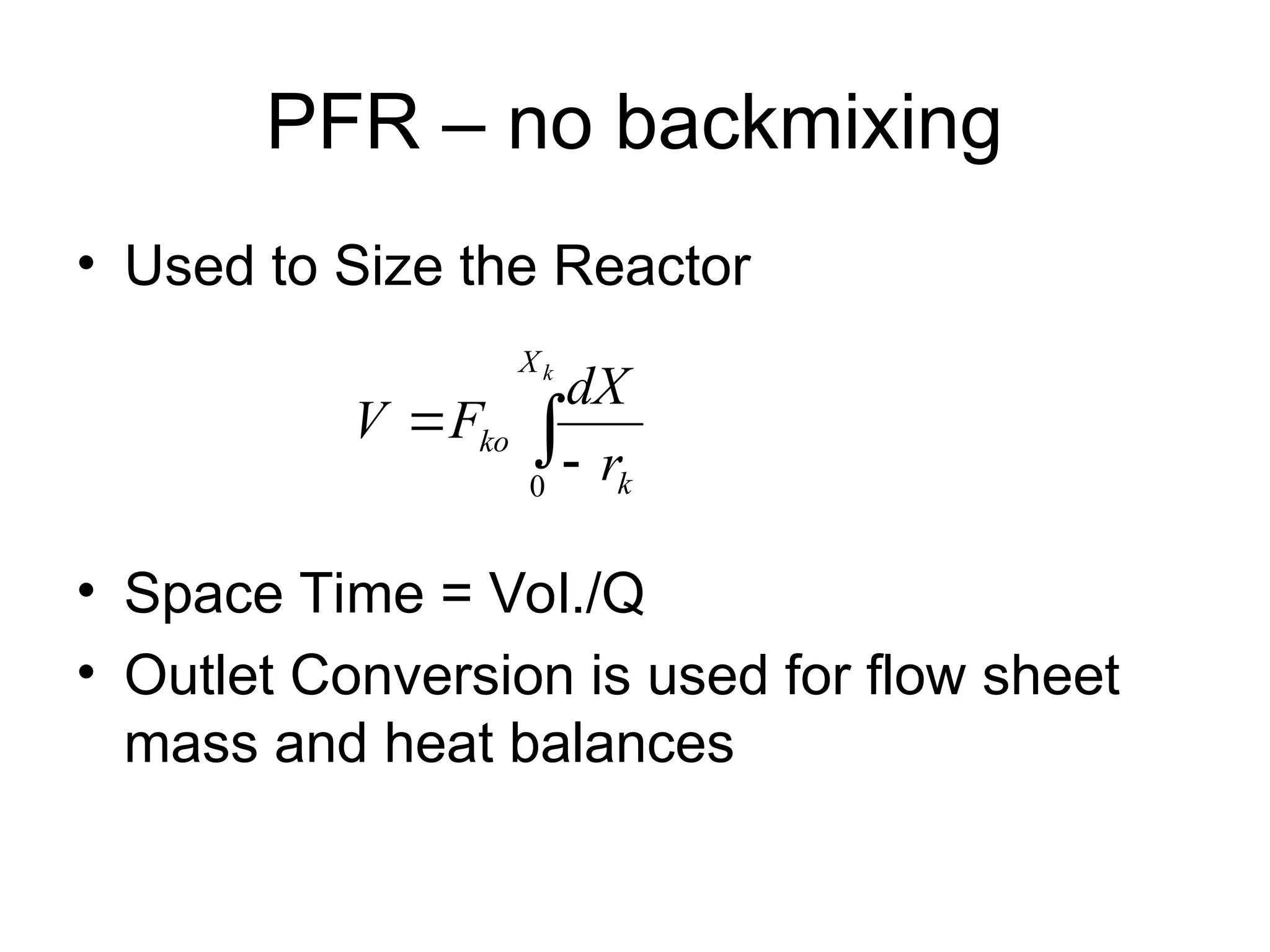
PFR – nobackmixing
• Used to Size the Reactor
• Space Time = Vol./Q
• Outlet Conversion is used for flow sheet
mass and heat balances
k
X
k
ko
r
dX
F
V
0
9.
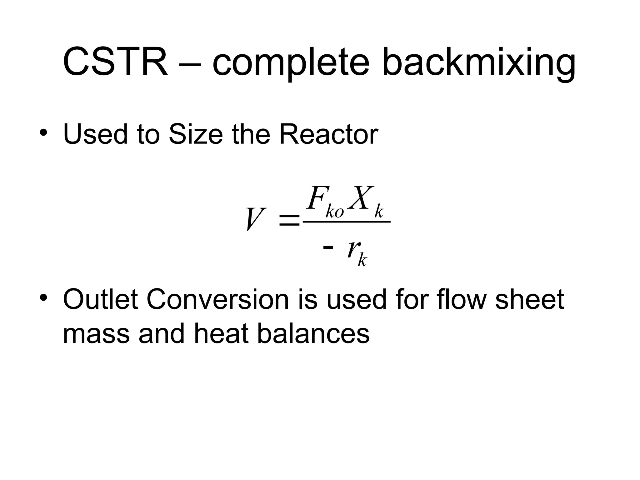
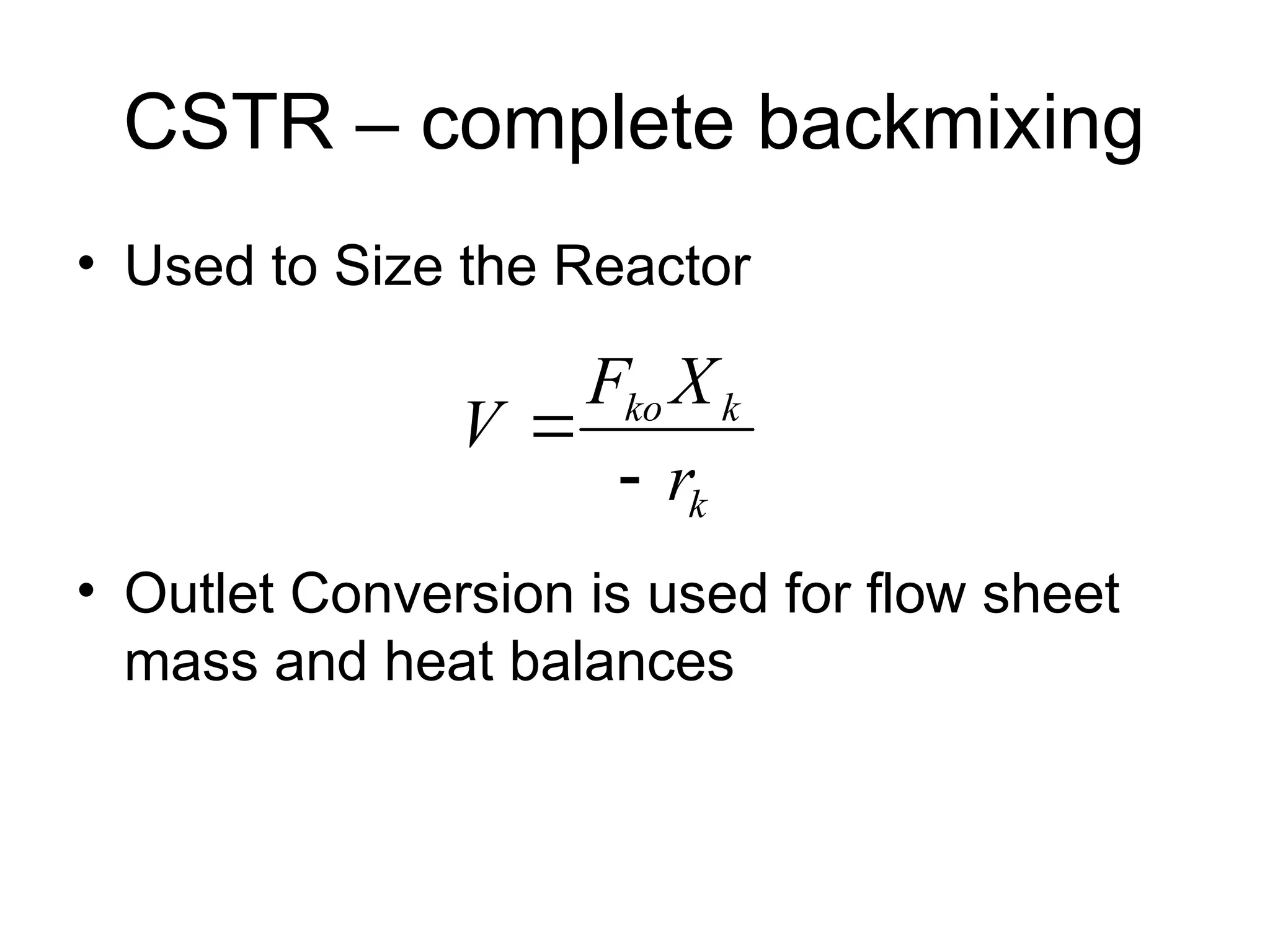
CSTR – completebackmixing
• Used to Size the Reactor
• Outlet Conversion is used for flow sheet
mass and heat balances
k
k
ko
r
X
F
V
10.
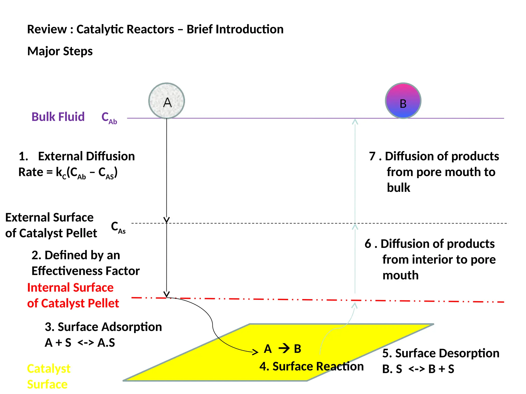
Review : CatalyticReactors – Brief Introduction
Major Steps
A B
Bulk Fluid
External Surface
of Catalyst Pellet
Catalyst
Surface
Internal Surface
of Catalyst Pellet
CAb
CAs
2. Defined by an
Effectiveness Factor
1. External Diffusion
Rate = kC(CAb – CAS)
3. Surface Adsorption
A + S <-> A.S
4. Surface Reaction
5. Surface Desorption
B. S <-> B + S
6 . Diffusion of products
from interior to pore
mouth
B
7 . Diffusion of products
from pore mouth to
bulk
11.
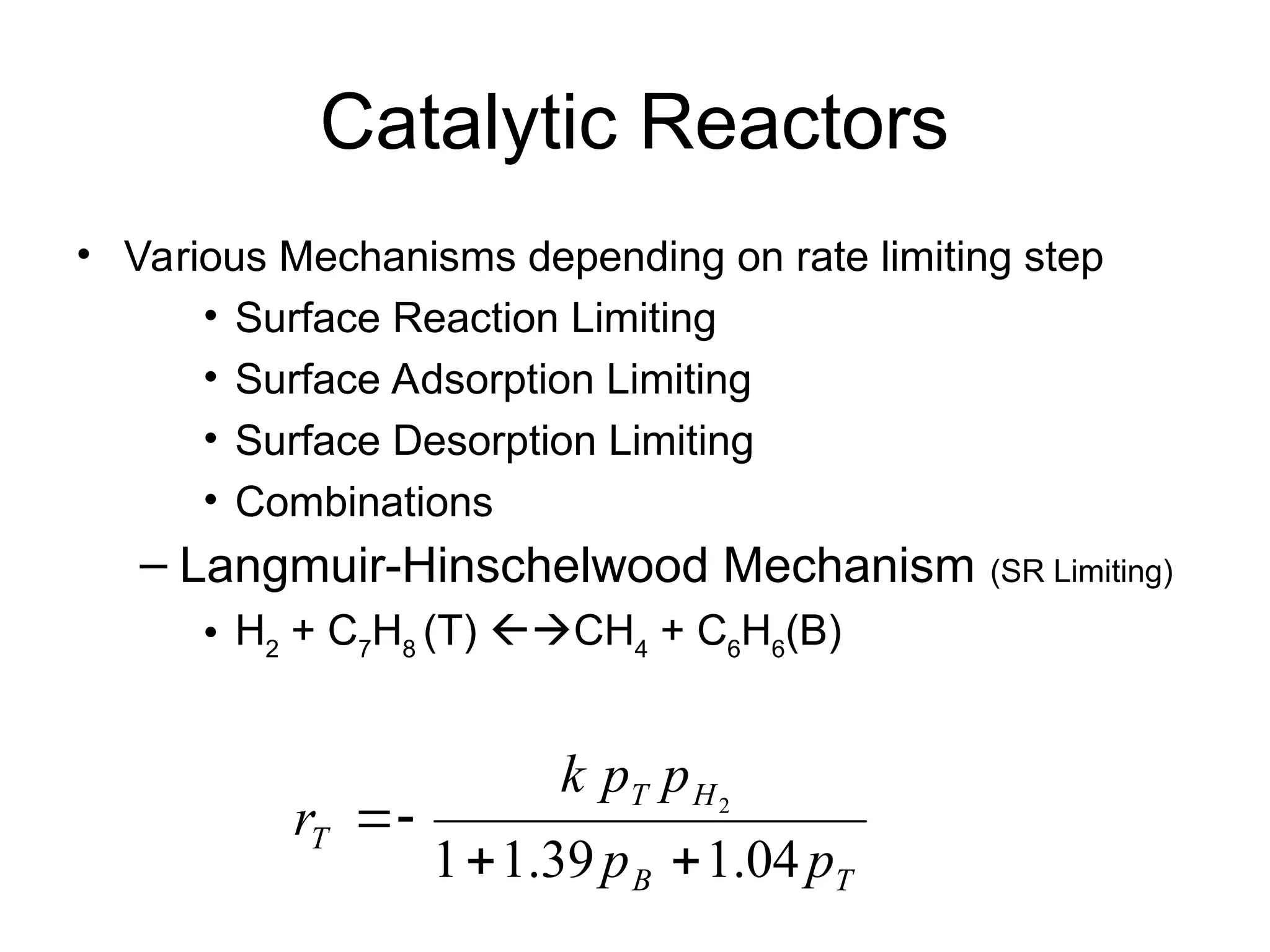
Catalytic Reactors
• VariousMechanisms depending on rate limiting step
• Surface Reaction Limiting
• Surface Adsorption Limiting
• Surface Desorption Limiting
• Combinations
– Langmuir-Hinschelwood Mechanism (SR Limiting)
• H2
+ C7
H8
(T) CH4
+ C6
H6
(B)
T
B
H
T
T
p
p
p
p
k
r
04
.
1
39
.
1
1
2
12.
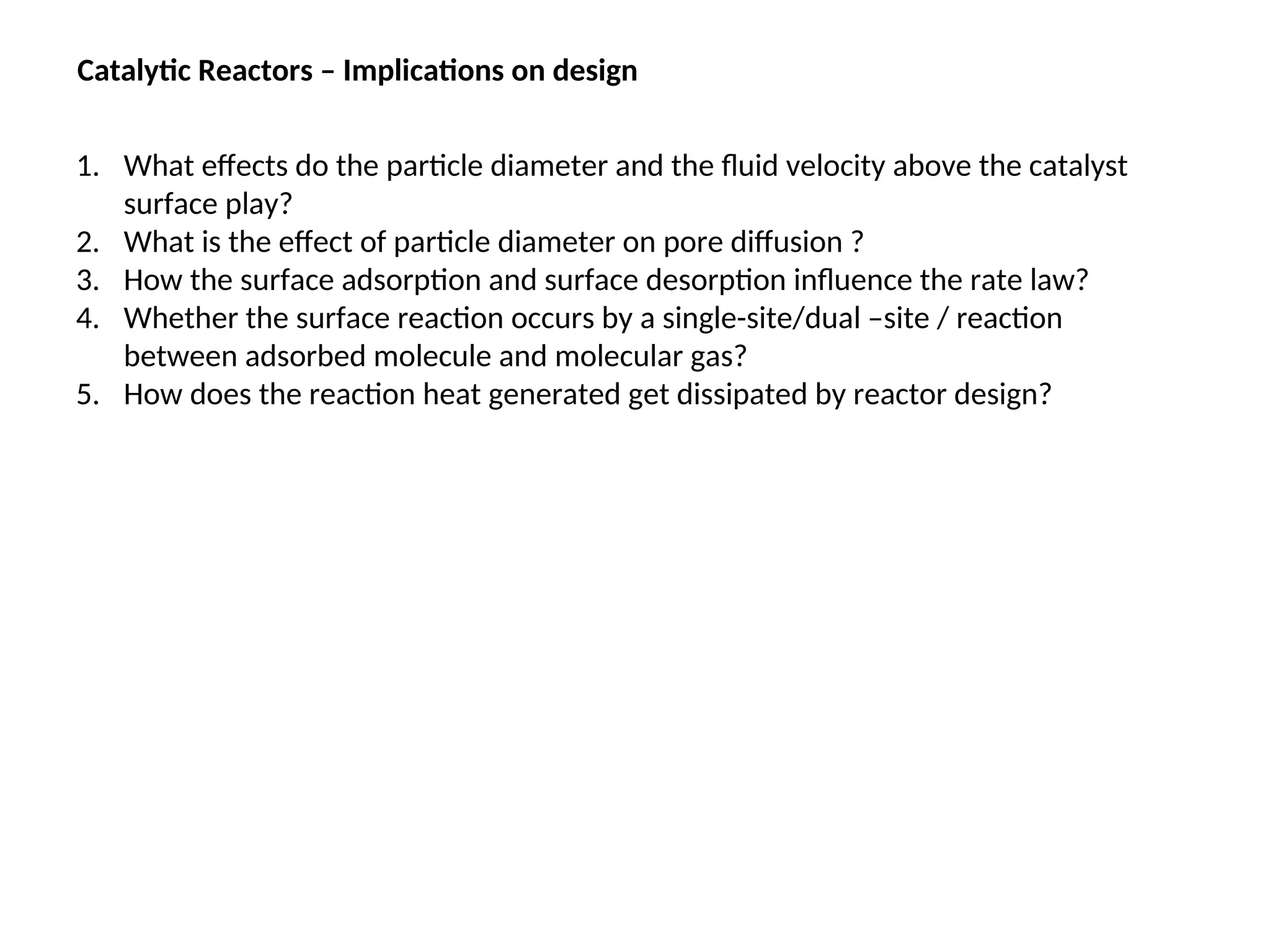
Catalytic Reactors –Implications on design
1. What effects do the particle diameter and the fluid velocity above the catalyst
surface play?
2. What is the effect of particle diameter on pore diffusion ?
3. How the surface adsorption and surface desorption influence the rate law?
4. Whether the surface reaction occurs by a single-site/dual –site / reaction
between adsorbed molecule and molecular gas?
5. How does the reaction heat generated get dissipated by reactor design?
13.
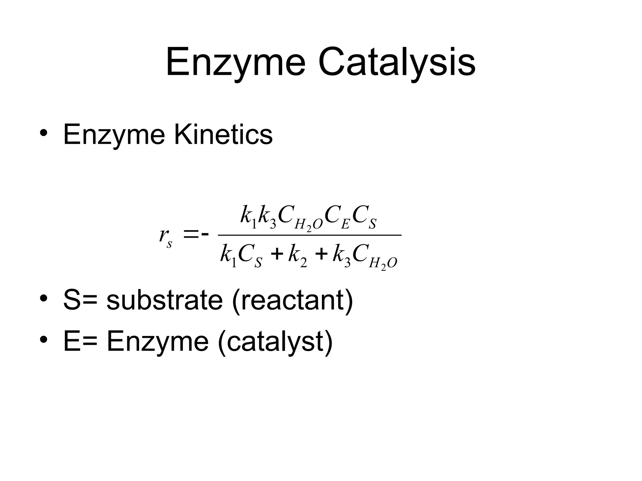
Enzyme Catalysis
• EnzymeKinetics
• S= substrate (reactant)
• E= Enzyme (catalyst)
O
H
S
S
E
O
H
s
C
k
k
C
k
C
C
C
k
k
r
2
2
3
2
1
3
1
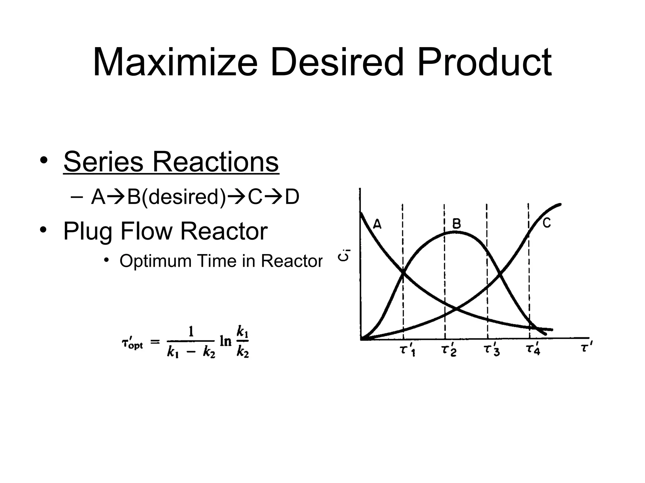
Optimization of DesiredProduct
• Reaction Networks
– Maximize yield,
• moles of product formed per mole of reactant consumed
– Maximize Selectivity
• Number of moles of desired product formed per mole of
undesirable product formed
– Maximum Attainable Region – see discussion in Chap’t. 7.
• Reactors (pfrs &cstrs in series) and bypass
• Reactor sequences
– Which come first
16.
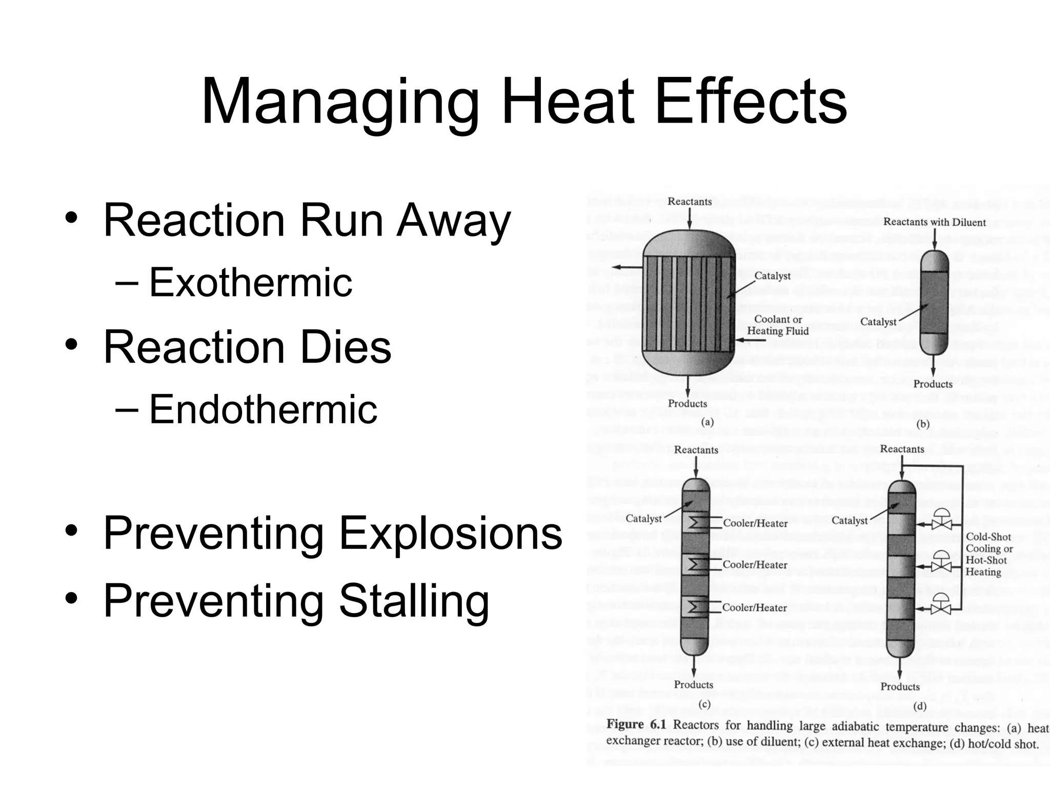
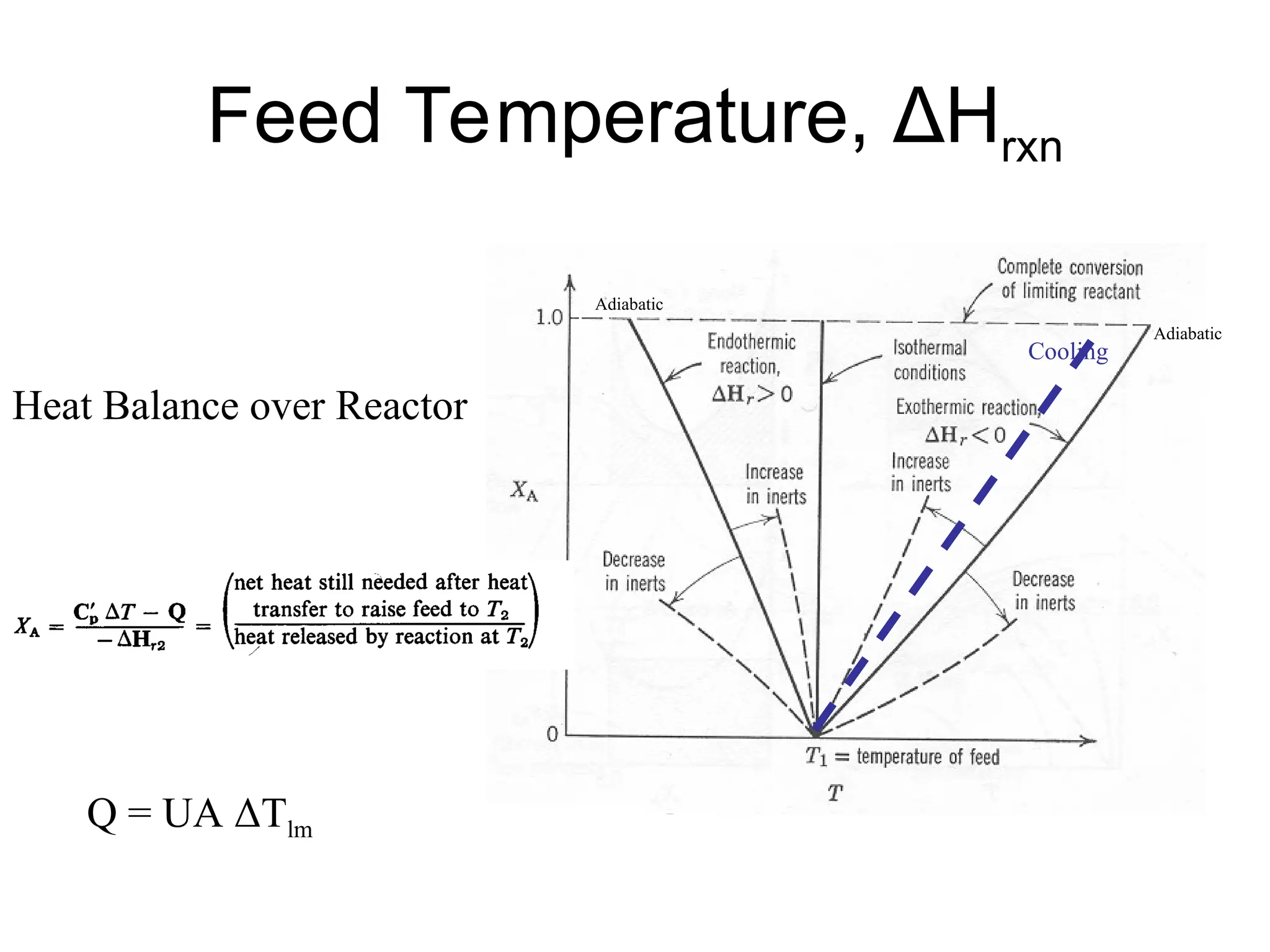
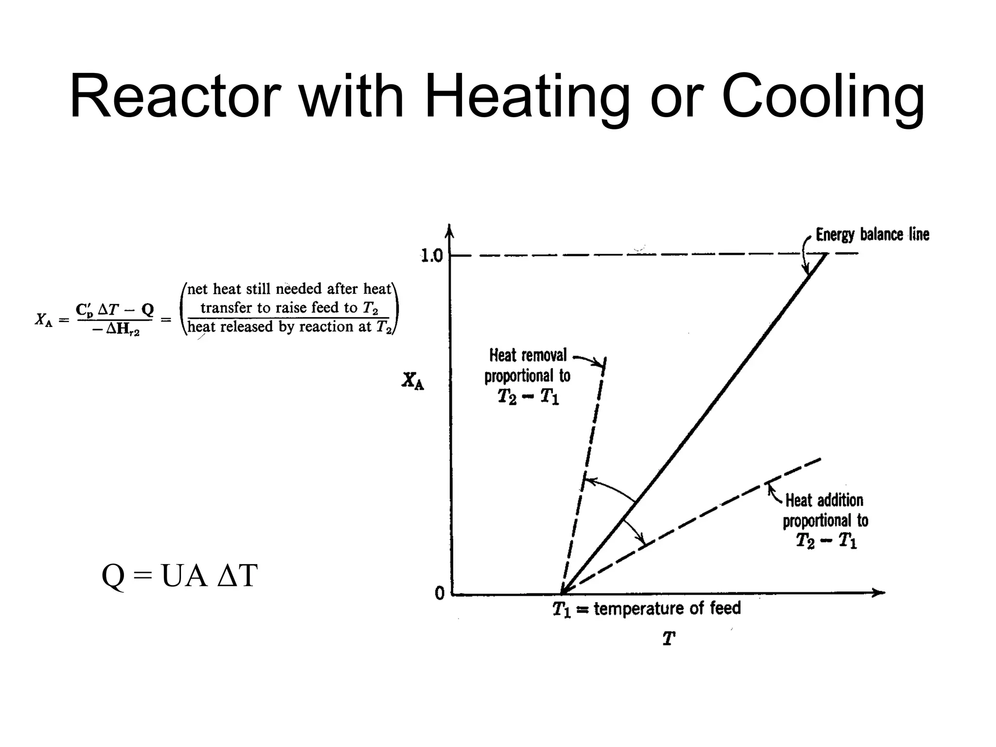
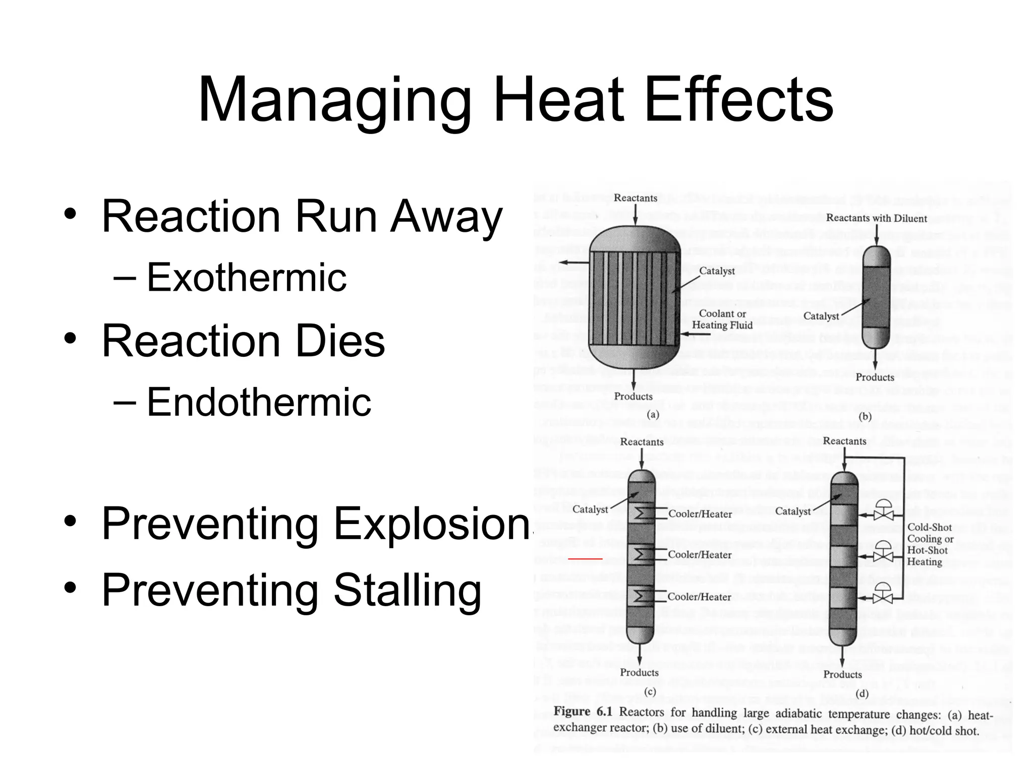
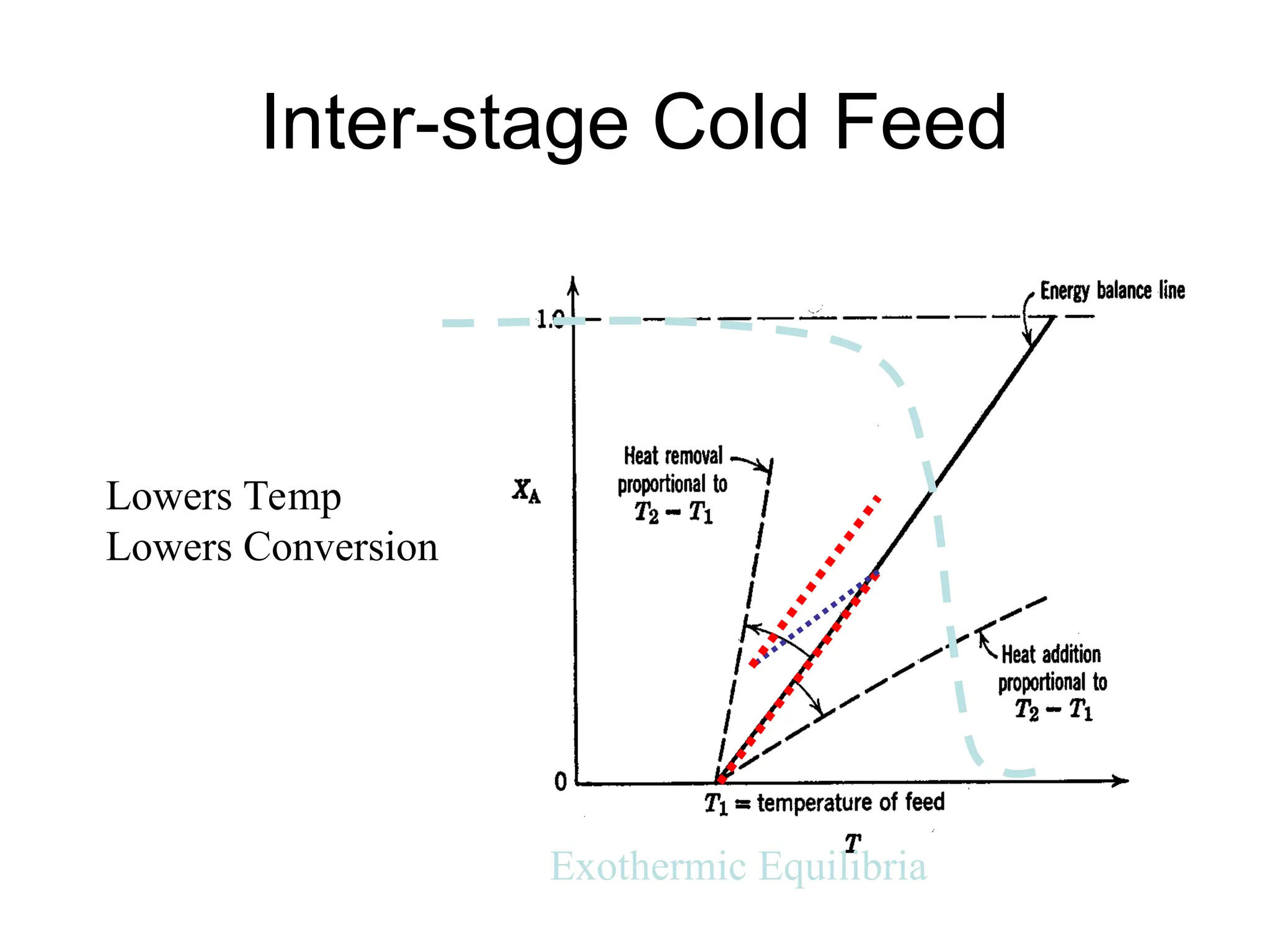
Managing Heat Effects
•Reaction Run Away
– Exothermic
• Reaction Dies
– Endothermic
• Preventing Explosions
• Preventing Stalling
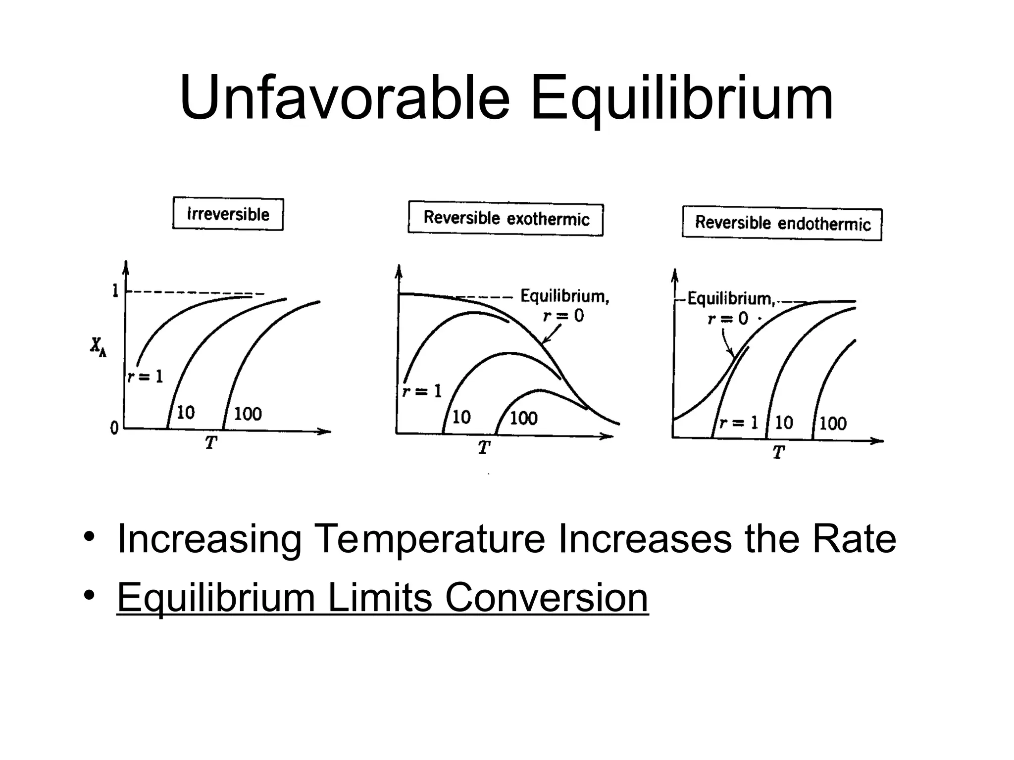
Equilibrium Reactor-
Temperature Effects
•Single Equilibrium
• aA +bB rR + sS
– ai activity of component I
• Gas Phase, ai = φiyiP,
– φi== fugacity coefficient of i
• Liquid Phase, ai= γi xi exp[Vi (P-Pi
s
) /RT]
– γi = activity coefficient of i
– Vi =Partial Molar Volume of i
2
ln
,
exp
RT
H
dT
K
d
RT
G
a
a
a
a
K
o
rxn
eq
o
rxn
a
B
a
A
s
S
r
R
eq
Van’t Hoff eq.
19.
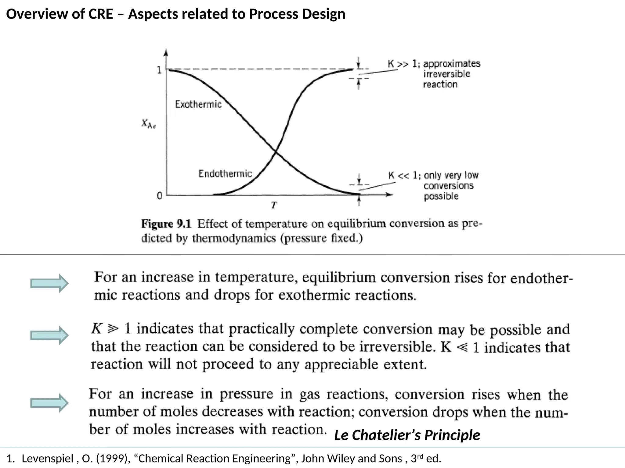
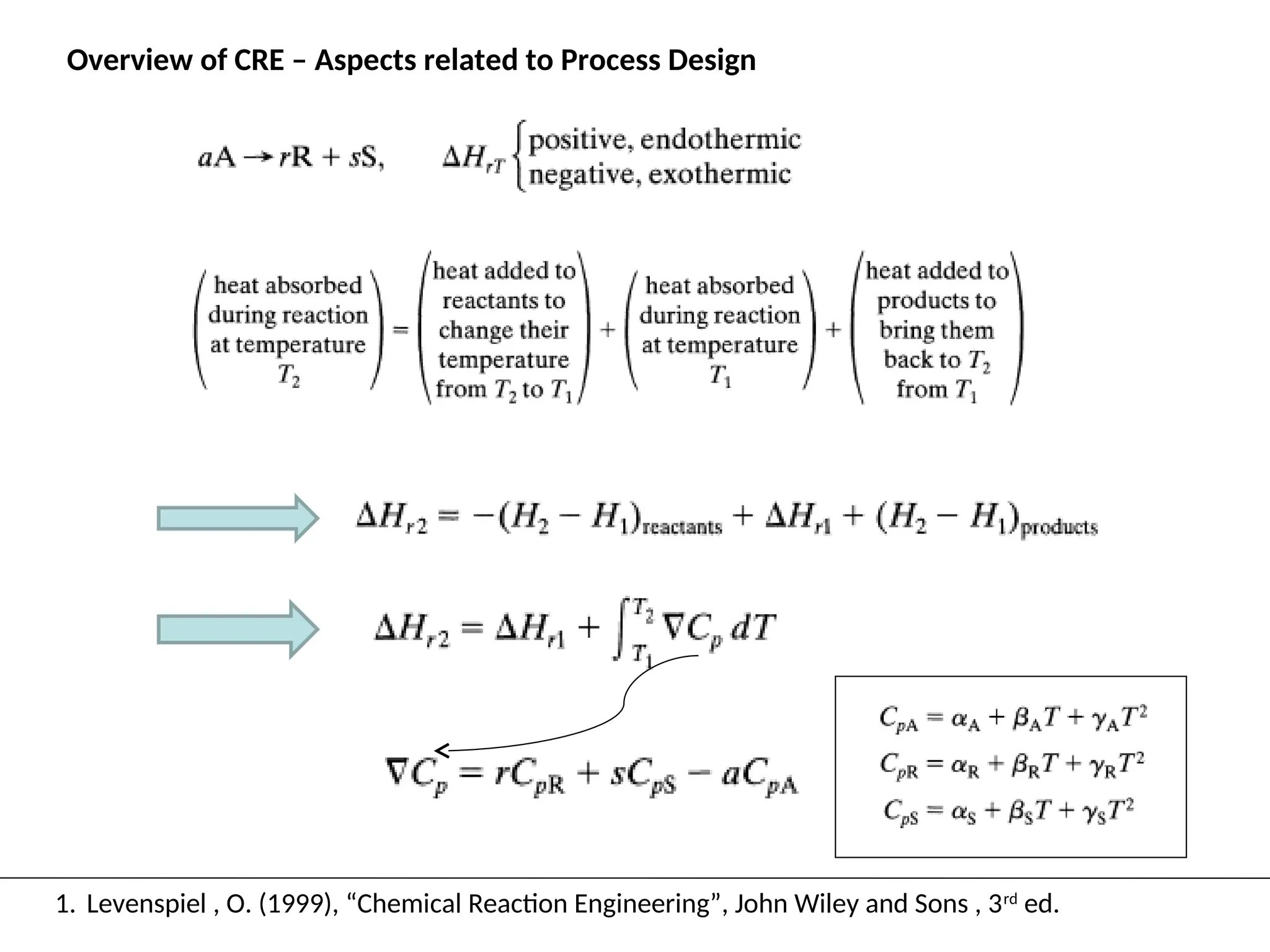
Overview of CRE– Aspects related to Process Design
1. Levenspiel , O. (1999), “Chemical Reaction Engineering”, John Wiley and Sons , 3rd
ed.
Le Chatelier’s Principle
Kinetic Reactors -CSTR & PFR –
Temperature Effects
• Used to Size the Reactor
• Used to determine the reactor dynamics
• Reaction Kinetics
RT
E
k
T
k
C
T
k
dt
dC
r
A
o
C
i
i
j
j
i
exp
)
(
)
(
1
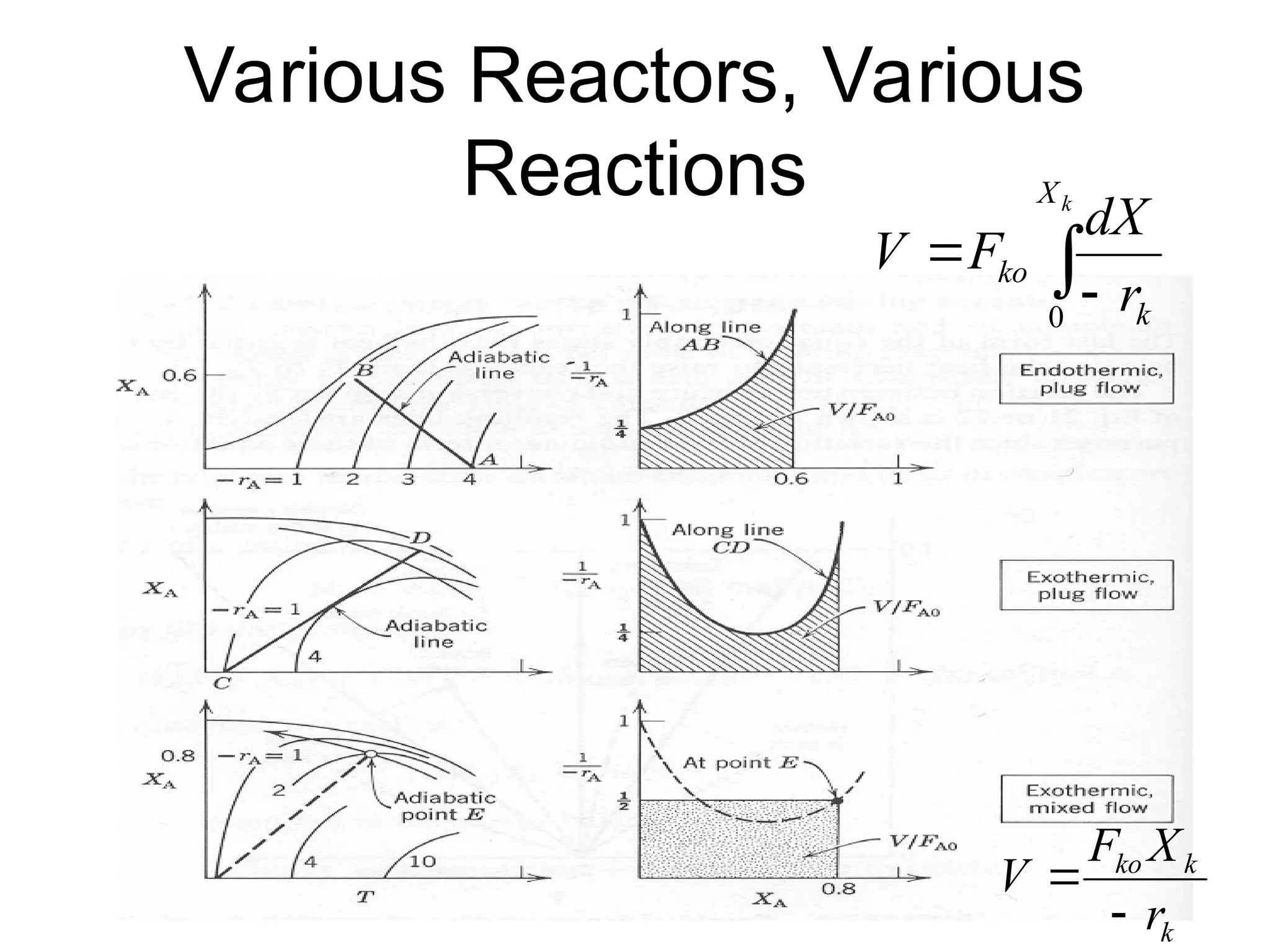
25.
PFR – nobackmixing
• Used to Size the Reactor
• Space Time = Vol./Q
• Outlet Conversion is used for flow sheet
mass and heat balances
k
X
k
ko
r
dX
F
V
0
26.
CSTR – completebackmixing
• Used to Size the Reactor
• Outlet Conversion is used for flow sheet
mass and heat balances
k
k
ko
r
X
F
V
Optimization of DesiredProduct
• Reaction Networks
– Maximize yield,
• moles of product formed per mole of reactant consumed
– Maximize Selectivity
• Number of moles of desired product formed per mole of
undesirable product formed
– Maximum Attainable Region – see discussion in Chap’t. 6.
• Reactors and bypass
• Reactor sequences
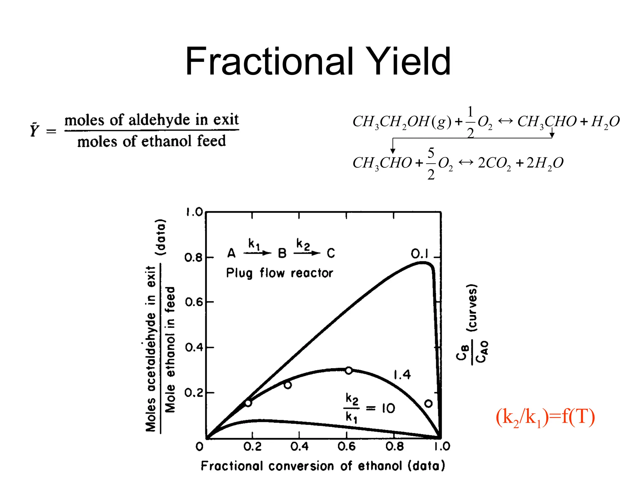
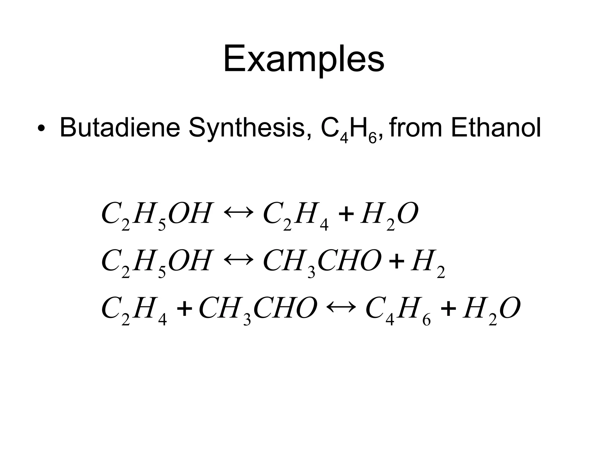
Examples
• Butadiene Synthesis,C4H6, from Ethanol
O
H
H
C
CHO
CH
H
C
H
CHO
CH
OH
H
C
O
H
H
C
OH
H
C
2
6
4
3
4
2
2
3
5
2
2
4
2
5
2
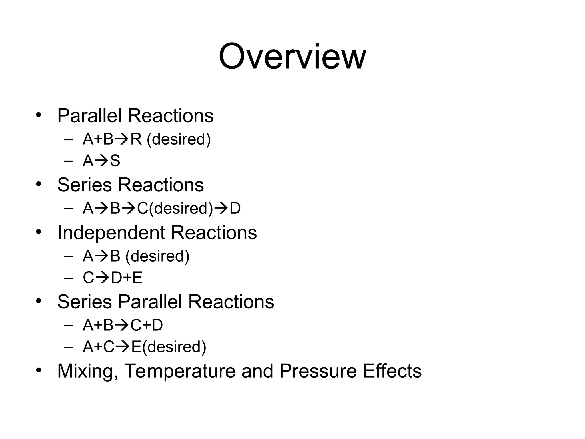
42.
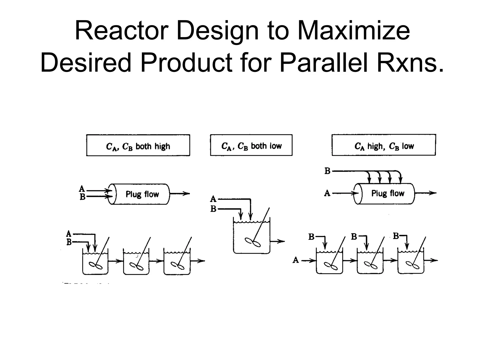
Rate Selectivity
• ParallelReactions
– A+BR (desired)
– A+BS
• Rate Selectivity
• (αD- αU) >1 make CA as large as possible
• (βD –βU)>1 make CB as large as possible
• (kD/kU)= (koD/koU)exp[-(EA-D-EA-U)/(RT)]
– EA-D > EA-U T
– EA-D < EA-U T
)
(
)
(
A
U
D
r
r
D/U
D
U
D
C
k
k
S U
D
U
B
C
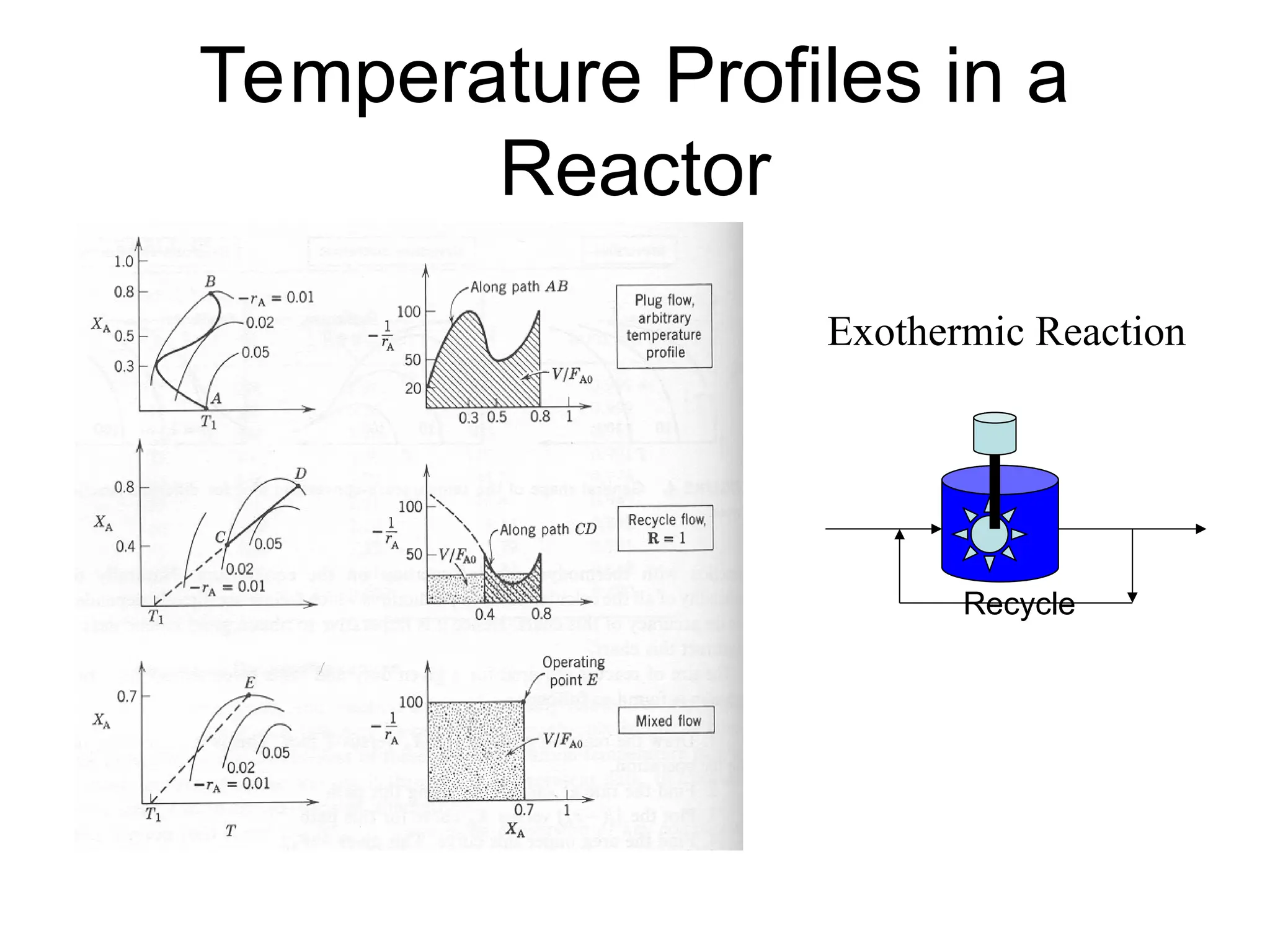
Real Reaction Systems
•More complicated than either
– Series Reactions
– Parallel Reactions
• Effects of equilibrium must be considered
• Confounding heat effects
• All have Reactor Design Implications
47.
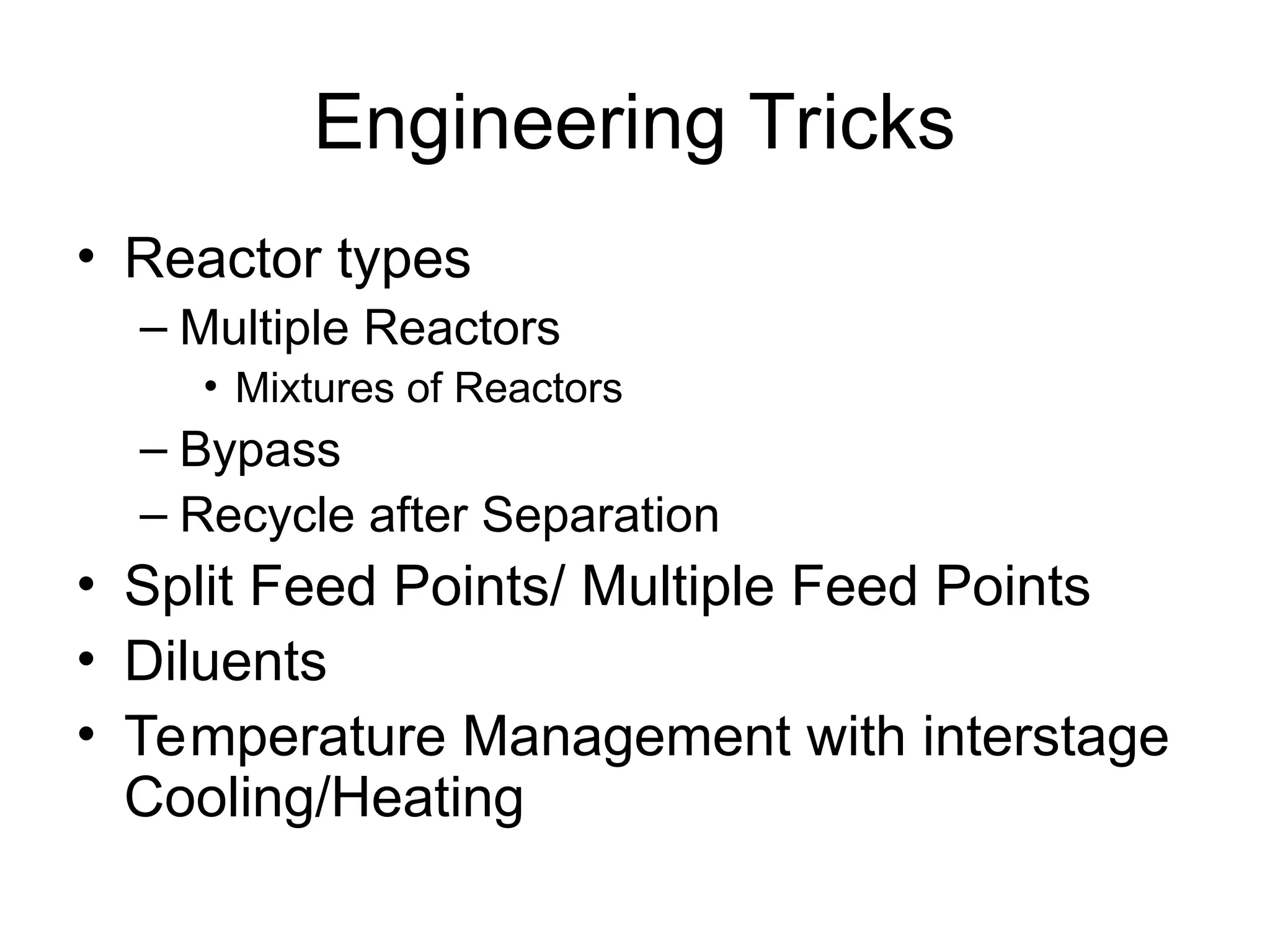
Engineering Tricks
• Reactortypes
– Multiple Reactors
• Mixtures of Reactors
– Bypass
– Recycle after Separation
• Split Feed Points/ Multiple Feed Points
• Diluents
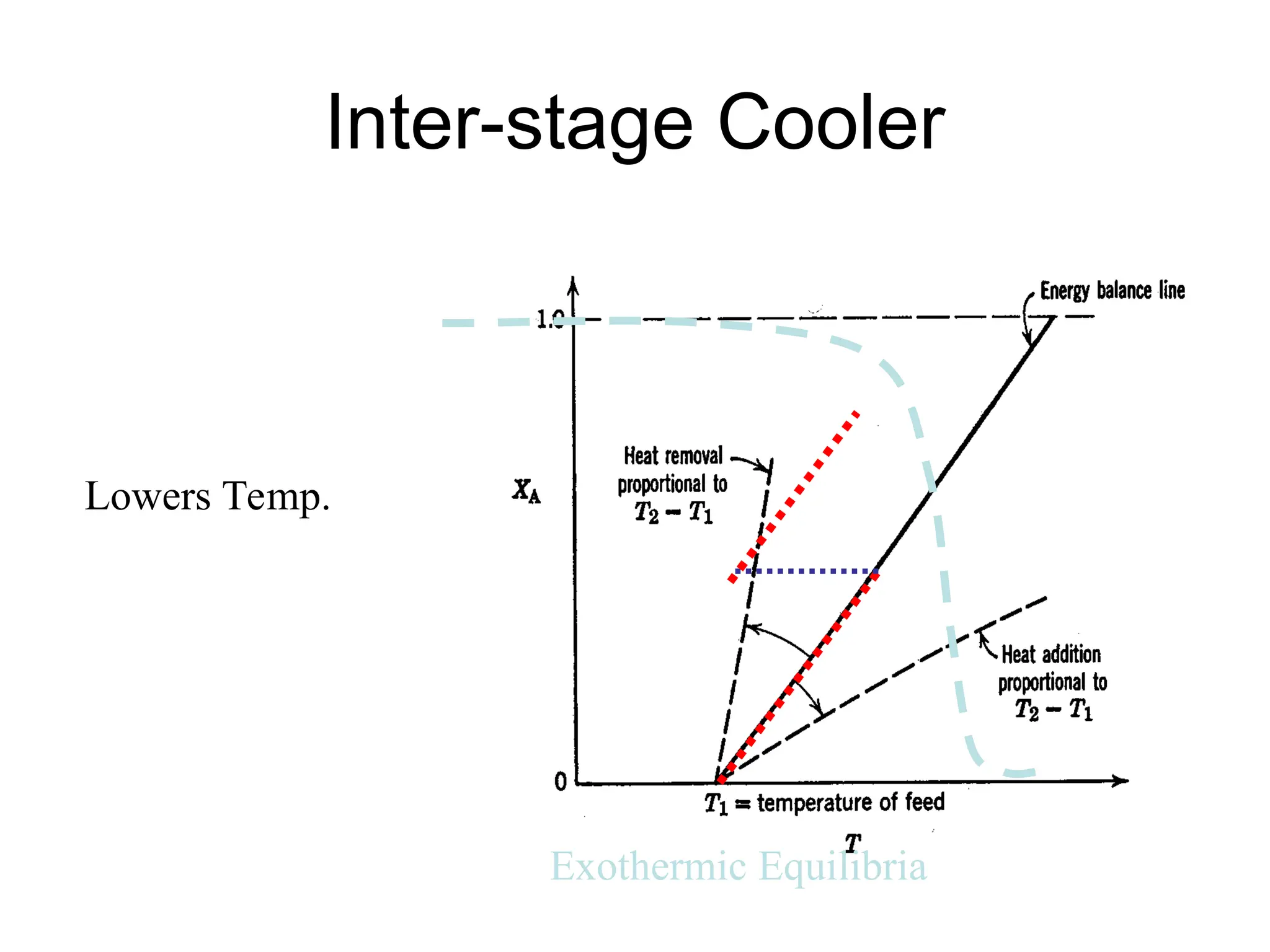
• Temperature Management with interstage
Cooling/Heating
48.
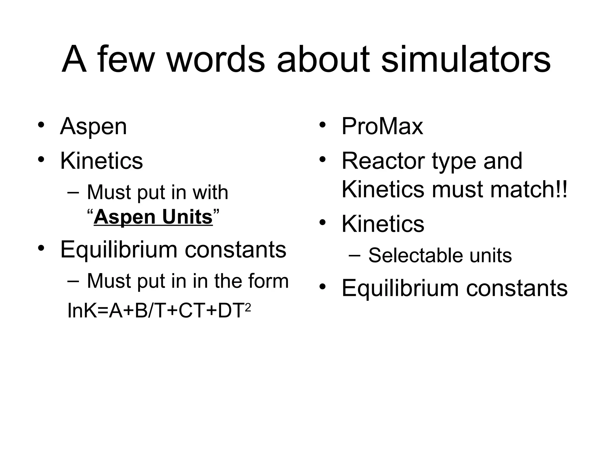
A few wordsabout simulators
• Aspen
• Kinetics
– Must put in with
“Aspen Units”
• Equilibrium constants
– Must put in in the form
lnK=A+B/T+CT+DT2
• ProMax
• Reactor type and
Kinetics must match!!
• Kinetics
– Selectable units
• Equilibrium constants
![Equilibrium Reactor-
Temperature Effects
• Single Equilibrium
• aA +bB rR + sS
– ai activity of component I
• Gas Phase, ai = φiyiP,
– φi== fugacity coefficient of i
• Liquid Phase, ai= γi xi exp[Vi (P-Pi
s
) /RT]
– γi = activity coefficient of i
– Vi =Partial Molar Volume of i
2
ln
,
exp
RT
H
dT
K
d
RT
G
a
a
a
a
K
o
rxn
eq
o
rxn
a
B
a
A
s
S
r
R
eq
Van’t Hoff eq.](https://image.slidesharecdn.com/13-l1-l2-reactordesign-250616063603-3a58922c/75/13-L1-L2-Reactor-Design-for-engineering-student-18-2048.jpg)


![Rate Selectivity
• Parallel Reactions
– A+BR (desired)
– A+BS
• Rate Selectivity
• (αD- αU) >1 make CA as large as possible
• (βD –βU)>1 make CB as large as possible
• (kD/kU)= (koD/koU)exp[-(EA-D-EA-U)/(RT)]
– EA-D > EA-U T
– EA-D < EA-U T
)
(
)
(
A
U
D
r
r
D/U
D
U
D
C
k
k
S U
D
U
B
C
](https://image.slidesharecdn.com/13-l1-l2-reactordesign-250616063603-3a58922c/75/13-L1-L2-Reactor-Design-for-engineering-student-42-2048.jpg)