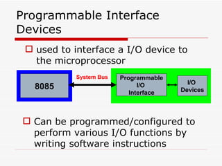
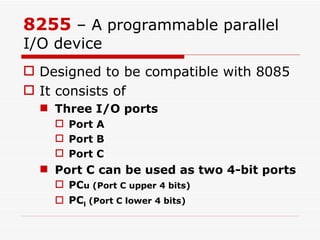
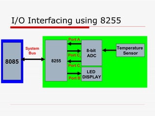
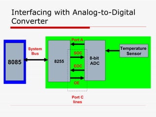
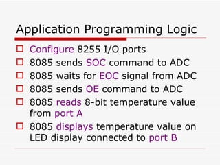
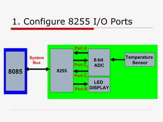
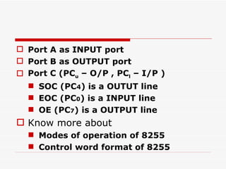
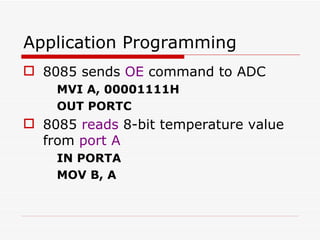
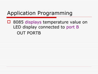
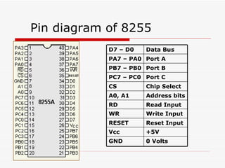
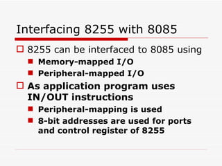
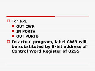
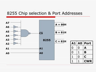
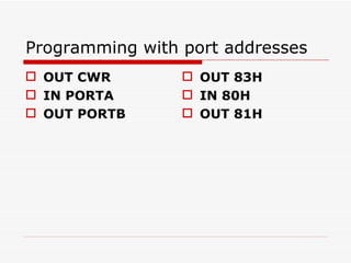
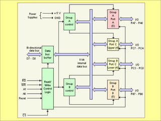
Programmable Peripheral Interface Devices Support chips :  8155 ,  8255 ,  8279 , 8254 , 8257 ,  8259,8251
Programmable Interface Devices used to interface a I/O device to the microprocessor 8085 Programmable I/O  Interface I/O  Devices System Bus Can be programmed/configured to perform various I/O functions by writing software instructions
8255  – A programmable parallel I/O device Designed to be compatible with 8085 It consists of Three I/O ports Port A Port B Port C Port C can be used as two 4-bit ports PC u (Port C upper 4 bits) PC l  (Port C lower 4 bits)
I/O Interfacing using 8255 8085 8255 8-bit  ADC System Bus LED  DISPLAY Temperature  Sensor Port A Port C u Port B Port C l
Interfacing with Analog-to-Digital Converter 8085 8255 8-bit  ADC System Bus Temperature  Sensor Port A Port C lines SOC EOC OE
Application Programming Logic Configure  8255 I/O ports 8085 sends  SOC  command to ADC 8085 waits for  EOC  signal from ADC 8085 sends  OE  command to ADC 8085  reads  8-bit temperature value from  port A 8085  displays  temperature value on LED display connected to  port B
Writing the program At this point, it will help us to understand, what we need to know more about 8255
1. Configure 8255 I/O Ports 8085 8255 8-bit  ADC System Bus LED  DISPLAY Temperature  Sensor Port A Port C u Port B Port C l
Port A as INPUT port Port B as OUTPUT port Port C (PC u  – O/P , PC l  – I/P ) SOC (PC 4 ) is a OUTUT line EOC (PC 0 ) is a INPUT line OE (PC 7 ) is a OUTPUT line Know more about Modes of operation of 8255 Control word format of 8255
Modes of Operation of 8255 Two primary modes of operation Parallel I/O mode Mode 0 (Simple Input/Output)  Mode 1 (Input/Output with Handshake) Mode 2 (Bidirectional data transfer) Bit Set/Reset Mode This application uses  Parallel I/O mode - Mode 0 Bit Set/Reset mode
Control Word for 8255 8255 has a 8-bit Control word register 8255 ports can be configured for operation by writing a appropriate control word in it
for  Parallel I/O 1 0 0 0 1 00 1 91H
for Bit Set/Reset Mode
Application Programming  Configure  8255 I/O ports MVI A, 91H OUT CWR Writing value 91H in Control Word Register of 8255  CWR represents the 8-bit port address of Control Word Register
Application Programming 8085 sends  SOC  (PC4=1)command to ADC MVI A, 00001001B OUT CWR Uses Bit Set/Reset mode of 8255
Application Programming 8085 waits for  EOC  signal from ADC WAIT: IN PORTC RAR JC WAIT EOC is taken to be active low
Application Programming 8085 sends  OE  command to ADC MVI A, 00001111H OUT PORTC 8085  reads  8-bit temperature value from  port A IN PORTA MOV B, A
Application Programming 8085  displays  temperature value on LED display connected to  port B OUT PORTB
Pin diagram of 8255 D7 – D0 Data Bus PA7 – PA0 Port A PB7 – PB0 Port B PC7 – PC0 Port C CS Chip Select A0, A1 Address bits RD Read Input WR Write Input RESET Reset Input Vcc +5V GND 0 Volts
Interfacing 8255 with 8085 8255 can be interfaced to 8085 using  Memory-mapped I/O Peripheral-mapped I/O As application program uses IN/OUT instructions  Peripheral-mapping is used 8-bit addresses are used for ports and control register of 8255
For e.g.  OUT CWR  IN PORTA OUT PORTB In actual program, label CWR will be substituted by 8-bit address of Control Word Register of 8255
8255 Chip selection & Port Addresses 8255 A2 A3 A4 A5 A6 A7 CS A1 A0 A1 A0 A = 80H B = 81H C = 82H A1 A0 Port 0 0 A 0 1 B 1 0 C 1 1 CWR
Programming with port addresses OUT 83H  IN 80H OUT 81H OUT CWR  IN PORTA OUT PORTB
Block diagram of 8255
 

1204 Ppi 8255

  • 1.
    Programmable Peripheral InterfaceDevices Support chips : 8155 , 8255 , 8279 , 8254 , 8257 , 8259,8251
  • 2.
    Programmable Interface Devicesused to interface a I/O device to the microprocessor 8085 Programmable I/O Interface I/O Devices System Bus Can be programmed/configured to perform various I/O functions by writing software instructions
  • 3.
    8255 –A programmable parallel I/O device Designed to be compatible with 8085 It consists of Three I/O ports Port A Port B Port C Port C can be used as two 4-bit ports PC u (Port C upper 4 bits) PC l (Port C lower 4 bits)
  • 4.
    I/O Interfacing using8255 8085 8255 8-bit ADC System Bus LED DISPLAY Temperature Sensor Port A Port C u Port B Port C l
  • 5.
    Interfacing with Analog-to-DigitalConverter 8085 8255 8-bit ADC System Bus Temperature Sensor Port A Port C lines SOC EOC OE
  • 6.
    Application Programming LogicConfigure 8255 I/O ports 8085 sends SOC command to ADC 8085 waits for EOC signal from ADC 8085 sends OE command to ADC 8085 reads 8-bit temperature value from port A 8085 displays temperature value on LED display connected to port B
  • 7.
    Writing the programAt this point, it will help us to understand, what we need to know more about 8255
  • 8.
    1. Configure 8255I/O Ports 8085 8255 8-bit ADC System Bus LED DISPLAY Temperature Sensor Port A Port C u Port B Port C l
  • 9.
    Port A asINPUT port Port B as OUTPUT port Port C (PC u – O/P , PC l – I/P ) SOC (PC 4 ) is a OUTUT line EOC (PC 0 ) is a INPUT line OE (PC 7 ) is a OUTPUT line Know more about Modes of operation of 8255 Control word format of 8255
  • 10.
    Modes of Operationof 8255 Two primary modes of operation Parallel I/O mode Mode 0 (Simple Input/Output) Mode 1 (Input/Output with Handshake) Mode 2 (Bidirectional data transfer) Bit Set/Reset Mode This application uses Parallel I/O mode - Mode 0 Bit Set/Reset mode
  • 11.
    Control Word for8255 8255 has a 8-bit Control word register 8255 ports can be configured for operation by writing a appropriate control word in it
  • 12.
    for ParallelI/O 1 0 0 0 1 00 1 91H
  • 13.
  • 14.
    Application Programming Configure 8255 I/O ports MVI A, 91H OUT CWR Writing value 91H in Control Word Register of 8255 CWR represents the 8-bit port address of Control Word Register
  • 15.
    Application Programming 8085sends SOC (PC4=1)command to ADC MVI A, 00001001B OUT CWR Uses Bit Set/Reset mode of 8255
  • 16.
    Application Programming 8085waits for EOC signal from ADC WAIT: IN PORTC RAR JC WAIT EOC is taken to be active low
  • 17.
    Application Programming 8085sends OE command to ADC MVI A, 00001111H OUT PORTC 8085 reads 8-bit temperature value from port A IN PORTA MOV B, A
  • 18.
    Application Programming 8085 displays temperature value on LED display connected to port B OUT PORTB
  • 19.
    Pin diagram of8255 D7 – D0 Data Bus PA7 – PA0 Port A PB7 – PB0 Port B PC7 – PC0 Port C CS Chip Select A0, A1 Address bits RD Read Input WR Write Input RESET Reset Input Vcc +5V GND 0 Volts
  • 20.
    Interfacing 8255 with8085 8255 can be interfaced to 8085 using Memory-mapped I/O Peripheral-mapped I/O As application program uses IN/OUT instructions Peripheral-mapping is used 8-bit addresses are used for ports and control register of 8255
  • 21.
    For e.g. OUT CWR IN PORTA OUT PORTB In actual program, label CWR will be substituted by 8-bit address of Control Word Register of 8255
  • 22.
    8255 Chip selection& Port Addresses 8255 A2 A3 A4 A5 A6 A7 CS A1 A0 A1 A0 A = 80H B = 81H C = 82H A1 A0 Port 0 0 A 0 1 B 1 0 C 1 1 CWR
  • 23.
    Programming with portaddresses OUT 83H IN 80H OUT 81H OUT CWR IN PORTA OUT PORTB
  • 24.
  • 25.

Editor's Notes