➥🔝 7737669865 🔝▻ Bhiwandi Call-girls in Women Seeking Men 🔝Bhiwandi🔝 Escor...
Volvo L70D Wheel Loader Service Repair Manual Instant Download.pdf
1. Service Information
Document Title: Function Group: Information Type: Date:
Description 200 Service Information 2014/4/8 0
Profile:
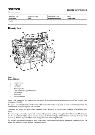
Description
Figure 1
Engine TD63KGE
1.
2.
3.
4.
5.
6.
7.
8.
Injection pump
Feed pump
Fuel filter
Water separator
Serial number and type designation
Turbocharger
Intercooler
Vibration damper
Loader L70D is equipped with a six-cylinder, four-stroke, direct-injection turbocharged diesel engine of low-emission type,
designation TD63KGE.
The engine has wet replaceable cylinder liners and two separate cylinder heads, each of which covers three cylinders. The
cylinder heads are interchangeable with each other.
Lubrication is achieved with a force-feed lubrication system where an oil pump presses lubricating oil to all lubrication
points.
The turbocharger supplies the engine with fresh air under pressure, resulting in a surplus of air. The volume of fuel injected
can thus be increased and the engine develops more power. The turbocharger is lubricated and cooled by the engine oil. It
is driven by the exhaust gases and so utilizes energy that would otherwise go to waste.
The engine is equipped with preheating of the induction air. The preheating coil (electric) is located in the inlet manifold. The
engine also has a cold starting device in the injection pump.
2. Figure 2
TD63KGE
1.
2.
3.
4.
Oil filter
Oil cooler
Coolant pump for intercooler
Preheating coil
Injection system, low-emission engine
The low-emission engine has retarded injection, i.e. fuel is injected when the piston is close to TDC. As a result, combustion
takes place at lower pressure and this substantially reduces the formation of NOx.
Figure 3
Pressurized fuel pipes
This requires injection to take place comparatively quickly and at high pressure, however, so that smoke and particulate
levels will not be worsened. Low-emission engines generally use higher injection pressures, which are achieved by means of
a nozzle with smaller holes and a different injection pump.
Do not under any circumstances bend or reshape the pipes. If a prestressed pipe is bent or deformed it will very likely break.
A damaged pipe must always be changed.
3. CAUTION
On account of the high injection pressure used, the injector delivery pipe connections must not be detached when the
engine is running.
STOP SOLENOID
Functional description
The engine’s fuel injection pump is equipped with a stop solenoid that is activated through the ignition SW101 and the
electronic unit CU201.
The purpose of CU201 is to provide an earth connection for the operating coil and holding coil in stop solenoid MA201.
Depending on the position of the ignition switch and the output signal from V-ECU, current is supplied to the various
terminals of CU201 as follows:
Turning off engine
Ignition switch in
position
Connection Voltage to electronic unit CU201
0 1 0 Volts
2 0 Volts
3, 6, 7, 8, 9, 11, 12 24 volts
1, 2 or 3 1 24 volts
2 0 Volts (24 volts at engine power reduction)
6,7, 8, 12 24 volts
3, 9, 11 0 Volt (operating position, MA201) 0.3 seconds
3, 9 24 Volts (holding position, MA201)
11 0 Volts (holding position, MA201)
With the ignition switch in position 0, current supplied to terminal 1 of electronic unit CU201 is cut off and so also is the
current to stop solenoid MA201. The solenoid’s spring moves the injection pump to the stop position.
Starting engine
With the ignition switch in position 1, 2 or 3 current is supplied to terminal 1 of electronic unit CU201. Stop solenoid MA201
is now supplied with current via terminal 6 and 12 of electronic unit CU201. Stop solenoid MA201 is activated and the
injection pump assumes the normal operating position.
Figure 4
Stop solenoid MA201
P Operating coil
H Holding coil
< 12 V feeds down into earth (31M which burns FU33)
Stop solenoid MA201
The stop solenoid consists of 2 coils, an operating coil (approx. 1 Ω ) and a holding coil (approx. 55 Ω). When the stop
solenoid is activated, a stronger current (approx. 20 A) is applied briefly (less than 1 sec.) to the operating and holding coils,
following which the operating coil is disconnected. A current of approx. 0.5 amps is now applied to the holding coil, which
keeps the stop solenoid in normal operating position.
4. Figure 5
Wiring diagram 3
The operating coil for stop solenoid MA201 is disconnected since its earth connection is interrupted via electronic unit
CU201 (terminals 3, 9 to 5, 10).
STARTING THE ENGINE
Functional description
With ignition switch SW101 in position 3, relay RE8’s coil is supplied with current via ignition switch terminal 50.
Relay RE9 is activated and starter motor terminal 50 is supplied with current via fuse FU8, relay RE8 (30 - 87) and relay RE9
(30 - 87A), thus activating the starter motor.
Relay RE9, starter inhibitor
When gear selector control SW402 is moved to the forward or reverse position, relay RE9’s coil receives current. Relay RE9 is
activated and cuts off the current supplied to starter motor MO201, which prevents the engine from being started when
forward or reverse gear is engaged.
Preheating
Functional description
The V-ECU checks the coolant temperature via the engine’s temperature sensor (SE205) and controls the preheating time as
follows:
Manual:
The preheating time is dependent on the temperature of the coolant:
Temperatures from -10 °C (14 °F) and up to +30 °C (86 °F):
Give varying preheating times between 50 and 10 seconds.
Temperatures below -10 °C (14 °F):
Give a preheating time of 50 seconds.
Automatic:
Preheating is activated automatically during starting and at an engine speed of >150 rpm if the temperature is below +10 °C
(50 °F) and "Additional preheating" is not activated.
5. Preheating time is 50 seconds at temperatures below -10 °C (50 °F).
Temperatures from -10 °C (14 °F) and up to +10 °C (50 °F) give preheating times between 50 and 10 seconds.
Sensor check: Open circuit, short-circuit in sensor circuit:
Always give a preheating time of 50 seconds when preheating is activated manually, regardless of the coolant temperature.
No preheating occurs when preheating is activated automatically.
Manual preheating
With ignition switch SW201 in position 2, preheating element HE201 can be activated with switch SW201 via V-ECU and
relay RE201.
When relay RE201 is activated, current goes to preheating coil HE201 and indicator lamp LC15 via fuses FH2 and FH1.
Indicator lamp LC15 remains on as long as preheating is activated.
Manual preheating can also be activated if V-ECU is by-passed.
Automatic heating
Automatic heating is activated by coolant temperature sensor SE205 via the V-ECU and relay RE201. Current is supplied to
preheating coil HE201 and control lamp LC15 via fuses FH2 and FH1.
Indicator lamp LC15 remains on as long as preheating is activated.
For automatic preheating to be activated, engine speed must exceed approx. 150 rpm and "Extra preheating" must not be
activated. Preheating will be disconnected if engine speed drops below approx. 100 rpm.
Additional heating
Additional heating is activated with the operator’s display panel .
For additional heating to be activated, the engine must run at >400 rpm for >2 seconds. The engine is heated a maximum of
4 times or up to +35 °C (95 °F) in a sequence of 40 seconds on and 20 seconds off.
Additional heating is disconnected if engine speed drops below approx. 100 rpm or the power supply drops below 12 V.
Additional heating is re-engaged if engine speed rises above approx. 15 rpm and the power supply remains at >12 V for at
least 2 seconds.
SPEED CONTROL (20 km/h (12 mph) and 30 km/h (19 mph))
Functional description
The engine is fitted with solenoid MA201 which controls the injection pump’s throttle arm to a limited engine speed
(1 800 rpm) at the registered maximum travel speed.
Solenoid MA201 is activated via the V-ECU and electronic unit CU201.
The purpose of the CU201 is to provide an earth connection for solenoid MA201’s operating coil and holding coil.
When the permitted speed (20 or 30 km/h (12 or 19 mph)) is registered by the V-ECU via travel speed sensor SE403, an
output signal goes from the V-ECU to CU201. Current is cut off to MA201 which then activates the throttle arm, causing it to
assume the position for limited rpm.
The following applies to 30 km/h (19 mph) travel speed control:
Control starts at 32 km/h (20 mph)
Control stops at 27 km/h (17 mph)
The following applies to 20 km/h (12 mph) travel speed control:
Control starts at 22 km/h (14 mph)
Control stops at 16 km/h (10 mph)
4th gear is blocked at 20 km/h (12 mph)
6. Service Information
Document Title: Function Group: Information Type: Date:
Compression
test
210 Service Information 2014/4/8 0
Profile:
Compression test
Op nbr
999 6643 Extractor
999 8009 Adapter
Compression tester 1–4 MPa (10–40 bar) (145–580 psi)
Figure 1
1. Connector
1. Place the machine in the service position, see Service Safety Rules, Section 1.
2. Clean the area round the injectors and remove all injectors.
NOTE!
The injectors must not be prised up. Extract them using tool 999 6643. Fit protective caps on all opened
connections.
3. Separate the connector for the stop solenoid.
4. Screw the compression tester to adapter 999 8009.
5. Crank the starter motor until the highest reading is obtained on the compression tester.
6. Restore the machine to operating condition.
7. Figure 2
1. Compression tester with adapter 999 8009
Compression at 3.3 r/s (200 rpm): approx. 2.4 MPa (348 psi)
Compression ratio: 18.3:1
Low compression readings in all cylinders indicates worn cylinder liners and/or worn piston rings. If one of the
cylinders has lower compression than the others this could be due to untight valves, broken piston rings or a
damaged cylinder head gasket
Departures from the value could also be due to the running-in status of the engine, temperature, lubricant
viscosity, battery condition, method of measurement, etc.
However, a comparison of the cylinder compression readings is the most important and the variations should not
exceed 10%.
8. Service Information
Document Title: Function Group: Information Type: Date:
Engine, installing 210 Service Information 2014/4/8 0
Profile:
Engine, installing
Op nbr 21072
1. Raise the engine.
Figure 1
2. Fit the bolts securing the hydraulic transmission to the engine and also the bolts securing the engine mountings to
the frame. Tighten the bolts.
3. Remove the engine lifting device (hoist or similar).
9. Figure 2
4. Fit the hydraulic tank bracket.
5. Fit the hydraulic tank. Refit detached hoses and connections.
6. For machines with hydraulically driven cooling fan (optional equipment) and the hydraulic pump mounted on the
engine. Reconnect detached hose connections on the hydraulic pump.
7. Refit the AC condenser and the oil cooler for the working hydraulics.
NOTE!
Do not separate any connections to the AC unit (optional equipment). The air-conditioning unit is pressurized and
refrigerant could inadvertently escape.
Figure 3
8. Attach the engine fuel lines. Refit the throttle control.
9. Fit the AC compressor
NOTE!
Do not separate any connections to the AC unit (optional equipment). The air-conditioning unit is pressurized and
refrigerant could inadvertently escape.
10. Plug the cable connector into sensor SE202 and the attach the cable harness with attendant connectors.
Figure 4
1.
2.
Sensor SE 202
Cable harness
10. 11. Connect other cables to the starter motor, alternator, optional equipment, etc.
12. Lift and position the engine hood support and bolt it in place, weight = 17 kg (37.5 lbs).
Figure 5
13. Plug in the connector for sensor SE208.
Figure 6
14. Lift the engine bonnet into place, weight = approx. 95 kg (210 lbs).
NOTE!
Take care to avoid damaging the rear window wiper when lifting the engine bonnet into place.
Figure 7
15. Refit the lower partitions and rubber cloth.
11. Figure 8
1.
2.
Partition
Rubber cloth
16. Refit the upper coolant hose on both sides of the partition. Attach other hoses to the cooling system.
17. Attach the exhaust pipe to the silencer.
18. Fit the side panels.
Figure 9
19. Fit the mudguards.
12. Figure 10
The illustration shows the extensible mudguard, weight = 27 kg (60 lbs).
20. Check the engine oil level.
21. Fill up with coolant.
22. Bleed the fuel system and turn on the battery disconnect switch.
23. Fill up the hydraulic system, see [Invalid linktarget] .
24. Release the frame joint lock.
25. Start the engine and warm it up. If necessary, top up the coolant. Check the functionality of the machine.
13. Service Information
Document Title: Function Group: Information Type: Date:
Engine, removing 210 Service Information 2014/4/8 0
Profile:
Engine, removing
Op nbr 21070
Ratchet block, 750 kg (1654 lbs) (2)
Sling, 2 m (6.6 ft) (1)
Shackle, 3/8" (1)
Figure 1
Draining, coolant
1. Secure the frame joint with the frame joint lock. Apply the parking brake and chock the wheels.
2. Turn off the electric power with the battery disconnect switch.
3. Drain the coolant.
4. Drain the hydraulic oil tank. Use the method described in [Invalid linktarget] .
5. For machines with hydraulically driven cooling fan and fan pump mounted on the engine. Detach the hose
connections on the pump. Use a clean receptacle to collect the hydraulic oil remaining in hoses and pump.
Plug opened pump and hose connections.
6. Remove the mudguards.
Figure 2
14. The illustration shows an extensible mudguard,
7. Remove the side hatches, weight = 32 kg (71 lbs).
Figure 3
8. Unplug the connector for sensor SE202. Also disconnect the attendant cable harness from the engine.
Unplug connections to starter motor and alternator.
Figure 4
1.
2.
Sensor SE202
Cable harness
9. Separate connector SE208 (located on engine bonnet support).
Figure 5
1. Connector SE208
15. 10. Remove the rubber cloth and lower partitions.
Figure 6
1.
2.
Partition
Rubber cloth
11. Detach the upper radiator hose on both sides of the partition.
Detach hoses connected to the cooling system header tank and air cleaner.
12. Remove the clamp on the silencer’s incoming connection, lower the silencer.
13. Detach the engine hood and lift it away together with the silencer, air cleaner and expansion tank.
NOTE!
Weight = approx. 90 kg (200 lbs).
Figure 7
NOTE!
Do not separate any connections to the AC unit (optional equipment). The air-conditioning unit is pressurized and
refrigerant could inadvertently escape.
14. Remove the air-conditioning unit’s condenser (optional equipment) from its attachment. Do not separate the
connections. Secure the condenser so that it will not be damaged as work continues.
15. Remove the oil cooler for the working hydraulics.
16. Figure 8
1. Oil cooler for working hydraulics
16. Remove the engine bonnet support.
Figure 9
NOTE!
Do not separate any connections to the AC unit (optional equipment). The air-conditioning unit is pressurized and
refrigerant could inadvertently escape.
17. Remove the AC compressor. Do not separate the connections. Secure the compressor to the frame.
18. Remove hoses and connections on the hydraulic tank.
Lift the hydraulic tank away.
19. Detach and remove the hydraulic tank bracket.
20. Remove and plug the engine fuel connections. Remove the throttle control.
21. Position a jack under the hydraulic transmission. Place a suitable block of wood between the hydraulic transmission
and the jack to avoid deformation of the hydraulic transmission sump.
17. Suggest:
If the above button click is invalid.
Please download this document
first, and then click the above link
to download the complete manual.
Thank you so much for reading
18. Figure 10
Jack underneath transmission
22. Attach a lifting device.
NOTE!
Engine weight = 660 kg (1455 lbs).
Figure 11
23. Undo the transmission housing bolts and the bolts securing the rear engine mountings to the frame.
24. Raise the engine at the rear by means of the ratchet block.
Lift out the engine.
25. Place the engine on a firm surface. Clean under the bed.