More Related Content
Similar to diagrama del modulo y sensores.pdf (20)
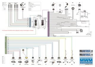
diagrama del modulo y sensores.pdf
- 1. A
1 2
4
3
5
A B C D E F
A
B C
D
B A
A B C D
A B C
A
B
C
D
E
F
G
H
J
Bk
Bk/Rd
Bk/Vl
Bk/Yw
Bl
Bk/Yw
Bk/Vl
Bk/Yw
Rd/Bk
Bk
Bl
Bk/Yw
Cyl. 1 Cyl. 4 Cyl. 3 Cyl. 2
Cyl. 1 Cyl. 3 Cyl. 2 Cyl. 5 Cyl. 6 Cyl. 4
“High Bank 1” “High Bank 2”
Injectors 0 455 120 167 (CRIN3)
Firing order 4 cyl.:
1 3 4 2
Firing order 6 cyl.(in-line engine):
1 5 3 6 2 4
ECM control order: (SV = Solenoide valve)
4 Cyl.:
Injector SV11 SV21 SV12 SV22
6 Cyl.:
Injector SV11 SV21 SV12 SV22 SV13 SV23
Cyl. 4
Cyl. 6
1 2 1 2 1 2 1 2 1 2 1 2
MPROP
1 2
Cylinder
Connector
-
16
pin
04
05
11
12
06
01
02
03
14
15
16
13
09
10
Bk/Rd
Gr/Bl
Vehicle
Connector
-
89
pin
TPS WIF
ECL VSS
Engine
Exhaust
Brake
Fuel high pressure pump with fuel
metering unit (ZME) (CP3.3NH)
0 445 020 101
64
68
1 2
Coolant level sensor
15
13
89
33
40
Engine speed for speedometer (tachometer)
ISO-K Interface
34
52
35
53
10
11
05
06
Term. 31 (BAT - )
03
02
09
08
Wire-size: BAT+1...BAT+4
?
Fuse 30A
V1
Fuse
Fuse 5A
Key switch
Ignition
switch
(+12)
Term. 30 (BAT+)
V3
39
56
Diagnost / Stop Lamp
Warning Lamp
79
78
82
48
29
Low idle switch
Accelerator pedal sensor 1
Ground digital
86
26
Parking brake switch
Exhaust brake switch
46
66
Water in fuel sensor
Clutch switch (Torque converter)
69
67
Vehicle speed sensor
Siemens VDO (2159.20)
V2
04
Switched battery plus output
41
49
72
74
Truck brake switch
Stop light switch
Diagnostic request switch
Two speed axle switch
To starter relay
Remarks:
Harness guidelines
K5/ESK2 Y 281 E22 D13E
DS - CV/ESA Y 445 R90 613
= twisted pair recommendede also recommended for all actuators
Vx = Butt connector
---------- = optional functions / nu = not used
..A = Customer Responsibility
Connector set:
0 462 YU3 DOH
ECM Part No:
0 281 020 128
Eletronic
Control Module
For the function of the ECM the vehicle configuration according to terminal diagram is mandatory
Legeng:
Yellow: Yw
Red: Rd
Green: Gn
Blue: Bl
Gray: Gr
Black: Bk
Brown: Br
Orange: Or
Violet: Vl
White: Wh
CMP
CKP
EGR Valve ECT
EOPT Turbo Actuator
T-MAP EFP MAF
EGR Sensor
Bk/Rd
Br
Wh/Bl
Wh/Gn
1 1
2 2
3 3
4 4
Rd
Wh
Bl/Bk
Bk/Wh
Bl/Gn
Bl/Bk
Shield Shield
1 2
Br
Gn/Wh
Wh/Bl
Wh
Bl/Bk
Wh
Yw/Bk
Wh/Gn
Br
Boost pressure and temperature
sensor (LDFT)
(0 281 002 845)
Oil pressure and temperature
sensor (ODFT)
(0 261 230 112)
Tyco EGR Status Analog input Crankshaft speed sensor (DG6)
(tone wheel with holes)
(0 281 002 214)
(Inductive)
Camshaft speed sensor (DG6)
(tone wheel with pins)
(0 281 002 411)
(Inductive)
Coolant temperature sensor
(0 281 002 209)
Rail pressure sensor (RDS4)
(0 281 002 930)
Hot Film Air mass sensor
(SIMAF SP8)
Norgren Turbo Actuator PWM Norgren EGR Actuator PWM
1 2
12 9 7 1 2 4 2
3 1 2 3
2 1 3
Engine
Connector
-
36
pin
25
36
33
34
24
28
32
27
07
06
15
26
12
14
13
21
02
17
35
Wh
Bl/Bk
Gn/Wh
22
18
16
Yw
Yw/Bk
Yw
Bl
23
19
09
10
1 2 3 1 2 3 4
Rd
Br
Bl Gn/Yw
Bk/Wh
Wh
Bk
Bk
Wh
C A
C A
5 4
Exhaust brake relay
Ground digital
C A
Switched battery plus output
Radiator Ground
Engine CAB Connector WIF Lamp
To the Fuse Box
(A2 Pin B)
WIF Lamp test
WIF Module
A B
D
H
D
H
J1939 Connector
Data Link connector