SlideShare a Scribd company logo
1 of 29
Download to read offline
Copyright  1999 Case France
Printed in France
Case Cre 7-22470GB November 1999
595SLE/595LSP LOADER BACKHOE SERVICE MANUAL
Table of contents
DIVISION/SECTION SECTION N° REFERENCE N°
1 GENERAL
Standard torque specifications and loctite product chart .................................1001 7-79451GB
Fluids and lubricants........................................................................................1002 7-22480GB
2 ENGINE
Engine and radiator removal and installation...................................................2000 7-21290GB
Specifications details .......................................................................................2401 7-26610GB
3 FUEL SYSTEM
4 ELECTRICAL
Electrical schematic .........................................................................................4001 7-26620GB
Battery..............................................................................................................4003 7-21330GB
Starter motor....................................................................................................4004 7-21340GB
Removal and installation of electrical components ..........................................4005 7-21350GB
Alternator .........................................................................................................4007 7-23790GB
Steering, loader and backhoe calibration.........................................................4008 7-26530GB
5 STEERING
Removal and installation of steering components ...........................................5000 7-23810GB
Steering specifications, pressure checks and troubleshooting ........................5001 7-21900GB
Steering control valve ......................................................................................5002 7-21390GB
Steering cylinder ..............................................................................................5003 7-21400GB
Front axle, four wheel drive machine/four wheel steer machine......................5007 7-21890GB
6 POWER TRAIN
Removal and installation of power train components ......................................6000 7-22540GB
Transmission specifications, pressure checks and troubleshooting ................6002 7-21430GB
Wheels and tyres .............................................................................................6003 7-22550GB
Gear box ..........................................................................................................6007 7-22560GB
Rear axle-four whell steer................................................................................6008 7-21600GB
7 BRAKES
Removal and installation of brake components ...............................................7000 7-23840GB
Disassembly and assembly of brake components...........................................7003 7-23190GB
8 HYDRAULICS
Removal and installation of hydraulic components..........................................8001 7-23210GB
Hydraulic specifications, troubleshooting and pressure checks.......................8002 7-26630GB
Cleaning the hydraulic system .........................................................................8003 7-21520GB
Hydraulic pump and unloader valve.................................................................8004 7-23250GB
Loader control valve.........................................................................................8005 7-23280GB
Cylinders ..........................................................................................................8006 7-26120GB
Backhoe control valve......................................................................................8007 7-23290GB
Extending dipperstick control valve..................................................................8008 7-21560GB
Priority demand valve ......................................................................................8010 7-21570GB
9 MOUNTED/EQUIPMENT
Pedals and levers ............................................................................................9001 7-23360GB
Loader..............................................................................................................9006 7-26140GB
Cab and Rops..................................................................................................9007 7-26600GB
Backhoe...........................................................................................................9008 7-26710GB
Seat and seat belt............................................................................................9009 7-23830GB
Removal and installation of components .........................................................9011 7-23850GB
Case
Copyright  1999 Case France
Printed in France
November 1999
Cre 7-79451GB
1001
STANDARD TORQUE SPECIFICATIONS
AND LOCTITE PRODUCT CHART
Section
1001
1001-2
Cre 7-79451GB Issued 11-99
TABLE OF CONTENTS
TORQUE SPECIFICATIONS - DECIMAL HARDWARE ..........................................................................................2
TORQUE SPECIFICATIONS - METRIC HARDWARE.............................................................................................3
TORQUE SPECIFICATIONS - STEEL HYDRAULIC FITTINGS...........................................................................4-5
LOCTITE PRODUCT CHART ..................................................................................................................................6
TORQUES SPECIFICATIONS
(DECIMAL HARDWARE)
Use the torques in this chart when special torques
are not given. These torques apply to fasteners with
both UNC and UNF threads as received from
suppliers dry, or when lubricated with engine oil. Not
applicable if special graphities, Molydisulfide greases,
or other extreme pressure lubricants are used.
Grade 5 Bolts,
Nuts and Studs
Size
Pound-
inches
Newton
metres
1/4 inch 8 to 11 12 to 15
5/16 inch 17 to 21 23 to 28
3/8 inch 35 to 42 48 to 57
7/16 inch 54 to 64 73 to 87
1/2 inch 80 to 96 109 to 130
9/16 inch 110 to 132 149 to 179
5/8 inch 150 to 180 203 to 244
3/4 inch 270 to 324 366 to 439
7/8 inch 400 to 480 542 to 651
1.0 inch 580 to 696 787 to 944
1-1/8 inchs 800 to 880 1085 to 1193
1-1/4 inchs 1120 to 1240 1519 to 1681
1-3/8 inchs 1460 to 1680 190 to 2278
1-1/2 inchs 1940 to 2200 2631 to 2983
NOTE : Use thick nuts with Grade 8 bolts.
Grade 8 Bolts,
Nuts and Studs
Size
Pound-
inches
Newton
metres
1/4 inch 12 to 15 16 to 20
5/16 inch 24 to 29 33 to 39
3/8 inch 45 to 54 61 to 73
7/16 inch 70 to 84 95 to 114
1/2 inch 110 to 132 149 to 179
9/16 inch 160 to 192 217 to 260
5/8 inch 220 to 264 298 to 358
3/4 inch 380 to 456 515 to 618
7/8 inch 600 to 720 814 to 976
1.0 inch 900 to 1080 1220 to 1465
1-1/8 inchs 1280 to 1440 1736 to 1953
1-1/4 inchs 1820 to 2000 2468 to 2712
1-3/8 inchs 2380 to 2720 3227 to 3688
1-1/2 inchs 3160 to 3560 4285 to 4827
1001-3
Cre 7-79451GB Issued 11-99
TORQUE SPECIFICATIONS
(METRIC HARDWARE)
Use the following torques when specifications are not
given.
These values apply to fasteners with coarse threads
as received from supplier, plated or unplated, or
when lubricated with engine oil. These values do not
apply if graphite or Molydisulfide grease or oil is used.
Grade 8.8 Bolts,
Nuts and Studs
Size
Pound-
inches
Newton
metres
M4 2 to 3 3 to 4
M5 5 to 6 7 to 8
M6 8 to 9 11 to 12
M8 19 to 23 26 to 31
M10 38 to 45 52 to 61
M12 66 to 79 90 to 107
M14 106 to 127 144 to 172
M16 160 to 200 217 to 271
M20 320 to 380 434 to 515
M24 500 to 600 675 to 815
M30 920 to 1100 1250 to 1500
M36 1600 to 1950 2175 to 2600
Grade 12.9 Bolts, Nuts and Studs
Usually the torque values specified for grade 10.9
fasteners can be used satisfactorily on grade 12.9
fasteners.
Grade 10.9 Bolts,
Nuts and Studs
Size
Pound-
inches
Newton
metres
M4 3 to 4 4 to 5
M5 7 to 8 9 to 11
M6 11 to 13 15 to 18
M8 27 to 32 37 to 43
M10 54 to 64 73 to 87
M12 93 to 112 125 to 150
M14 149 to 179 200 to 245
M16 230 to 280 310 to 380
M20 450 to 540 610 to 730
M24 780 to 940 1050 to 1275
M30 1470 to 1770 2000 to 2400
M36 2580 to 3090 3500 to 4200
8.8
10.9
12.9
1001-4
Cre 7-79451GB Issued 11-99
TORQUE SPECIFICATIONS
(STEEL HYDRAULIC FITTINGS)
Tube OD
Hose ID
Thread
size
Pound-
inches
Newton
metres
37 Degree
flare fitting
1/4 inch/
6.4 mm
7/16-20 6 to 12 8 to 16
5/16 inch/
7.9 mm
1/2-20 8 to 16 11 to 22
3/8 inch/
9.5 mm
9/16-18 10 to 25 14 to 34
1/2 inch/
12.7 mm
3/4-16 15 to 42 20 to 57
5/8 inch/
15.9
7/8-14 25 to 58 34 to 79
3/4 inch/
19.0 mm
1-1/16-12 40 to 80 54 to 108
7/8 inch/
22.2 mm
1-3/16-12 60 to 100 81 to 135
1.0 inch/
25.4 mm
1-5/16-12 75 to 117 102 to 158
1-1/4 inch/
31.8 mm
1-5/8-12 125 to 165 169 to 223
1-1/2 inch/
38.1 mm
1-7/8-12 210 to 250 285 to 338
Split flange
mounting screws
Size
Pound-
inches
Newton metres
5/16-18 15 to 20 20 to 27
3/8-16 27 to 40 36 to 53
7/16-14 35 to 45 47 to 61
1/2-13 55 to 65 74 to 88
5/8-11 140 to 150 190 to 203
Tube OD
Hose ID
Thread
size
Pound-
inches
Newton
metres
Straight threads
with O-ring
1/4 inch/
6.4 mm
7/16-20 12 to 19 16 to 26
5/16 inch/
7.9 mm
1/2-20 16 to 24 22 to 34
3/8 inch/
9.5 mm
9/16-18 24 to 40 34 to 54
1/2 inch/
12.7 mm
3/4-16 42 to 67 57 to 91
5/8 inch/
15.9
7/8-14 58 to 92 79 to 124
3/4 inch/
19.0 mm
1-1/16-12 80 to 128 108 to 174
7/8 inch/
22.2 mm
1-3/16-12 100 to 160 136 to 216
1.0 inch/
25.4 mm
1-5/16-12 117 to 187 159 to 253
1-1/4 inch/
31.8 mm
1-5/8-12 165 to 264 224 to 357
1-1/2 inch/
38.1 mm
1-7/8-12 250 to 400 339 to 542
Case
Copyright  1999 Case France
Printed in France
October 1999
Cre 7-21290GB
2000
ENGINE AND RADIATOR
REMOVAL AND INSTALLATION
Section
2000
2000-4
Cre 7-21290GB Issued 10-99
RADIATOR REMOVAL
Put identification tags on all disconnected hoses and
wires. Close disconnected hoses and fittings with
caps and plugs.
STEP 1
Park the machine on a level surface. Raise the loader
and install the support strut to hold the loader.
STEP 2
Open the hood.
STEP 3
Remove the bolts, washers, and nuts from the pivot
point on the hood.
STEP 4
Have another person help with the following proce-
dure :
A. Remove the retainers from the hood struts and
disconnect the hood struts from the stud.
B. Remove the hood from the machine.
STEP 5
Slowly remove the radiator cap.
NOTE : During installation, fill the radiator and cool-
ant reservoir completely. See Section 1002 for cool-
ant specifications. Start and run the engine until the
coolant is at operating temperature. Stop the engine
and check for leakage. When the coolant is cold,
check the coolant reservoir level. Add coolant as
required. Never remove the radiator cap to check the
coolant level in the radiator.
STEP 6
Depressurize the hydraulic system as follows see
section 8002.
STEP 7
Disconnect the hoses from the hydraulic filter.
STEP 8
Remove and fit blaks to the expansion reservoir
hoses.
WARNING : Do not remove the cap when the
engine is hot. The circuit is still under pressure
and you could be scalded.
!
STEP 9
Tag and disconnect the wires on the audible warning
device.
STEP 10
Tag and disconnect the wires on the hydraulic filter
obstruction indicator.
STEP 11
789M250A
Release the fluid pipes (1) and electrical connections
(2) to the screen wash bottle (3) and tie back to the
chassis.
3
2
1
3
2
1
2000-5
Cre 7-21290GB Issued 10-99
STEP 12
CI98G516
Remove the hardwere (1), the retaining pins (2), the
washers (3) and support (4).
STEP 13
CI98G517
Disconnect the overflow hose (1) from the radiator
neck.
STEP 14
Loosen the clamp and disconnect the upper radiator
hose (2).
1
4
3
2
2
3
1
1
3
2
4
STEP 15
Loosen the clamp and disconnect the lower radiator
hose (3).
STEP 16
Loosen the clamp and disconnect the air cleaner
hose (4).
STEP 17
CI98G517
Position a suitable drainage container beneath the
hydraulic hose (5) and disconnect the hose from the
oil cooler (9).
NOTE : Fit blanks to the hose and the oil cooler con-
nection.
STEP 18
Repeat step (5) for the remaining hydraulic hoses (6),
(7) and (8).
STEP 19
Remove the for radiator retaining screw.
STEP 20
Install a suitable sling around the radiator and
remove the radiator.
NOTE : Installation of the radiator is the reverse of
removal.
8
6
7
5
9
2000-6
Cre 7-21290GB Issued 10-99
PERSPECTIVE VIEW
CI98G505
21
16
28 2 1
8
16
15 2
12
4
3
25 26
22
27
25
26
22
21
23
20
24
5
17
19
7 6
9
17
18
10
15
14
11
16
13
1. Hose
2. Collar
3. Hose
4. Collar
5. Seal
6. Shroud
7. Radiator
8. Cap, filler
9. Cooler, oil
10. Bracket
11. Nut
12. Screw
13. Washer
14. Stanchion
15. Washer
16. Nut
17. Bracket
18. Bracket
19. Collar
20. Nut
21. Hose
22. Clamp
23. Tank, expansion
24. Bracket
25. Screw
26. Washer
27. Plug
28. Grommet
2000-7
Cre 7-21290GB Issued 10-99
ENGINE REMOVAL
Put identification tags on all disconnected hoses and
wires. Close disconnected hoses and fittings with
caps and plugs.
STEP 1
Remove the radiator see page 4.
STEP 2
Disconnect the battery.
STEP 3
CI98G518
Remove the hose clip (4) from the air filter hose (5) at
the turbocharger inlet.
STEP 4
Support the air filter assembly (1) and remove the
three bolts (2) from the cylinder head and two bolts
(3) from the exhaust bracket. Remove the air filter
assembly.
5
4
3
1
2
2
STEP 5
789M257A
789M256A
Install the engine lifting bracket (6) using two of the
bolts (2) from the air filter bracket. The bracket is part
of the machine tool kit.
6
2
2
6
2000-8
Cre 7-21290GB Issued 10-99
STEP 6
CI98G519
Release the spring (1) and remove the exhaust pipe
(2).
STEP 7
Release the clip (3) on the silencer to turbocharger
connection and remove the nuts, washers and spac-
ers (4). Remove the silencer (5) from the bracket (6).
STEP 8
Remove the three bolts and washers (7) from the
exhaust bracket and remove the bracket.
STEP 9
Remove the hydraulic oil pump drive shaft (see sec-
tion 8004).
6
3
5
7
2
1
4
STEP 10
789M259A
Disconnect the throttle cable (15) from the fuel injec-
tion pump lever (14) and the bracket (16).
STEP 11
789M287A
Release the hose clips (19) on the heater hoses (17)
at the thermostat housing (18). Remove the hoses
and tie back under the scuttle.
14
16
15
14
15
16
19
18
17
17
18
19
2000-9
Cre 7-21290GB Issued 10-99
STEP 12
789M261A
Remove the four bolts (20) in the hydraulic pump
drive coupling (21) and remove the drive shaft (22).
STEP 13
789M262A
Release the hose clips (24) on the transmission filler
flexible pipe (26), remove the two bolts and nuts (23)
and (28) in the support bracket (27) and the nut and
bolt (29) and (30) in the dipstick pipe support.
22
21
20
22
20
21
29, 30 28
27
26
25
23
24
24
23
30
29 28
27
26
25
STEP 14
Release the dipstick pipe coupling (25) on the trans-
mission and remove the dipstick assembly.
STEP 15
789M263A
Remove the nut (32) from the wiring cover (31) on the
starter motor (33) and remove the cover.
STEP 16
789M264A
Remove the bolt and nut (36) in the clip (35) for the
transmission oil cooler pipe (34), and release the
pipe.
33
32
31
33
31
32
35
36
34
35
36
34
2000-10
Cre 7-21290GB Issued 10-99
STEP 17
Disconnect and tag all wiring connections from the
engine. These include the starter motor, the alterna-
tor, the water temperature switch, the oil pressure
switch, the thermostat unit, the air filter restriction
switch and the fuel injection pump stop solenoid.
STEP 18
789M265A
Remove the front floor mat (37) in the cab. Remove
the four screws (39) from the centre front floor plate
(38) and remove the plate.
STEP 19
CI98G501
Remove the six screws (41) from the gear lever tower
(40) and slide the tower up the lever (42).
39
38
37
37
39 38
44
43
46
40
41
42
45
STEP 20
Remove the six screws (41) from the gear lever tower
(40) and slide the tower up the lever (42).
STEP 21
Disconnect the clutch switch wiring connection (44)
and remove the spring (46) from the shift lever.
STEP 22
Remove the bolt and nut (43) and (45) from the shift
lever and remove the lever from the transmission.
STEP 23
Put the wiring ties which attach the electrical harness
to the support rail at the rear of the engine.
STEP 24
Release the oil cooler hose clamp on the right hand
side of the chassis.
STEP 25
789M288A
Disconnect the fuel inlet and discharge pipe (47) and
(48) from the fuel lift pump.
48
47
48
47
2000-11
Cre 7-21290GB Issued 10-99
STEP 26
789M270A
Remove the four bolts (52) and the two bearing caps
(51) from the rear coupling. Lower the propshaft (49).
Make sure that the needle roller bearing cups (50) on
the rear coupling are taped to the joint.
STEP 27
789M271A
Remove the four bolts (54) and the inspection plate
(55) from the bottom of the bell housing (53).
52
51
50
49
50
52
51
49
53
54
55 54
55
53
STEP 28
789M272A
Remove the eight flywheel to torque converter bolts
(56) and the washers (57) from the flex plate assem-
bly (58).
STEP 29
789M273A
Remove all except two of the spacer housing bolts
(59).
58
56,57
56, 57
57
56
57
56
58
59
59
2000-12
Cre 7-21290GB Issued 10-99
STEP 30
Position a trolley jack under the transmission, next to
the front axle drive coupling flange. Raise the jack
into contact with the transmission but DO NOT lift the
transmission.
STEP 31
Attach the special lifting bracket to the engine.
STEP 32
789M256A
Using a suitable hoist attached to the lifting bracket,
apply tension to the lift chains. DO NOT raise the
engine.
STEP 33
789M257A
Loosen the two bolts (62) and the nuts (60) from each
engine bracket (61).
62
61
60
60
61
62
STEP 34
789M276A
Remove the centre bolt (67), the nuts (64) and the
washers (63) and (66) from each transmission
mounting plate (65).
STEP 35
Remove the rear propshaft.
STEP 36
Using the hoist and trolley jack, raise the engine/
transmission unit sufficient to remove the engine
mountings. (approximately 40 mm (1.5 in)).
STEP 37
Lower the engine/transmission unit and move it
towards the rear of the machine until the rear prop-
shaft slicing joint is completely closed.
STEP 38
Remove the two bolts in the spacer housing.
65
63
64
66
67
66
67
64
63
65
2000-13
Cre 7-21290GB Issued 10-99
STEP 39
Hold the transmission to the rear, and move the
engine forward on the hoist to disengage the torque
converters spigot. Make sure that the torque con-
verter does not disengage from the transmission
input shaft when the engine moves forward.
STEP 40
Remove the engine from the machine.
Installation
NOTE : Install the engine in the reverse order of the
removal but note the following :
1.
789M277A
Before installation of the engine, make sure that the
torque converter is correctly installed in the transmis-
sion. The flex plate face (68) must be at least 50 mm
(2.0 in) from the transmission flywheel cover face
(69) (measurement A). If the measurement A is 40
mm (1.5 in) or less, the torque converter is not cor-
rectly installed and must be removed and installed
correctly.
2. During assembly of the engine to the transmis-
sion, make sure that the torque converter spigot
enters the fly wheel bush correctly. To check,
rotate the torque converter as the engine and
transmission come together.
A
69
68
69
68
3. Torque tighten attaching parts as follows :
Flywheel to torque converter flexible
plate bolts..................................28 Nm (21 lbf ft)
Rear coupling bearing cap bolts 37 Nm (27 lbf ft)
Coupling flange bolts.................48 Nm (35 lbf ft)
Starter motor friction nuts..........36 Nm (26 lbf ft)
4. Before starting the engine, do steps 3 through 8.
5. Bleed air from fuel system (see section 3410).
6. Check the transmission oil level (see section
6002).
7. Check the engine oil level.
8. Replenish the radiator and header tank with
coolant.
9. Check the hydraulic oil level.
10. Carry out a complete functional test of the
machine. Check all connections and joints for
leakage. Check all fluid levels with the engine
stopped and cold.
4004-3
Cre 7-21340GB Issued 10-99
Special tools
0 - 20 V DC voltmeter
0 - 150 A ammeter
Mechanical tachometer 0 - 10,000 rev/min.
Tightening Torques
Nm lbf ft
Solenoid main ‘BAT’ terminal M8 stud 6.0 4.5
Cable fixing nut M10 stud 12.0 9.0
Solenoid terminal M8 nut 6.0 4.5
Solenoid terminal M10 nut 12.0 9.0
Starter terminal 1/4 BSF nut 4.0 3.0
Solenoid end-cover screws 2.0 1.5
Solenoid unit screws 6.0 4.5
Brush-plate screws 7.0 5.0
Starter earth nuts 8.0 6.0
Pole shoes fixing screws 41.0 30
Through bolts 11.0 8.0
Eccentric pivot pin lock-nut 20.0 15.0
Specifications
Pilot diameter 12.71 mm (0.5 in)
Light running speed 5500 - 8000 rev/min.
Light running current/voltage 115A at 11V
Pinion end clearance
when engaged 0.13 - 1.14 mm (0.005-0.045 in)
New brush length 28.51 mm (1.226 in)
Renew brushes at 8 mm (0.3 in)
Spring pressure in workint 11.6 N (42 oz.)
position with new brushes
4004-4
Cre 7-21340GB Issued 10-99
Removing and installing the starter motor
Removing the starter motor
Remove the starter motor as follows:
1. Disconnect the battery see section 4003.
NOTE : Make sure the key is removed from the start
switch on the side console.
2. Open the hood.
3. Remove the protective cover (13), the nut (12)
and the cover (14) from the solenoid (4).
4. Note the installed positions of the electrical
cables (9) and (17).
5. Remove the nut (11), the washer (10) and dis-
connect the four electrical cables (9) from the
starter motor (8).
6. Remove the two nuts (15), the two washers (16)
and disconnect the three electrical cables (17)
from the solenoid (4).
7. Attach the electrical cables (9) and (17) to the
structure of the engine with temporary ties.
8. Support the starter motor (8) and solenoid (4).
Remove the three nuts (7) and the “P-clip”
mounting bracket (6) from the studs (5).
9. Slide the starter motor (8) together with the sole-
noid (4) from the studs (5) and remove from the
engine.
10. Put a warning sign in the cab to tell persons not
to start the engine.
Installing the starter motor
NOTE : The installation of the starter motor is the
reverse of the removal.
Install the starter motor in the reverse order of the
removal but note the following:
1. Torque tighten the nuts (12): 12 Nm.
2. Torque tighten the nut (11): 6 Nm.
3. After installation do the following tests:
• The battery voltage under load test, refer to
page 7.
• The starter motor terminal voltage under load
test, refer to page 8.
• The voltage drop on the insulated line test, refer
to page 8.
• The voltage drop across solenoid contact refer to
page 9.
The voltage drop in earth line test, refer to
page 10.
4004-5
Cre 7-21340GB Issued 10-99
789M048A
4004-6
Cre 7-21340GB Issued 10-99
Disassembling the starter motor
Disassemble the starter motor as follows:
1. Remove the starter motor, refer to page 4.
2. Remove the solenoid assembly, refer to page
14.
3. Remove the end-cover, refer to page 12 (steps 3
through 6).
4. Remove the field winding brushes (10) from
brush plate.
5. Remove the rubber grommet (13).
6. Slacken the locknut and remove the pivot pin
(4). (The pivot is eccentric to the screw thread to
allow adjustment of the pinion gear end-clear-
ance).
7. Remove housing (2) and the pinion engagement
lever (1).
8. Remove the armature and pinion assembly (9)
from the motor body.
9. Use a suitable tube to punch the thrust-collar (6)
towards the pinion and expose the snap-ring (5).
10. Remove the snap-ring (5).
11. Remove the thrust-collar (6).
12. Pull the pinion and the roller clutch (7), off the
armature shaft.
13. Pull the intermediate plate (8) off the armature
shaft.
14. Remove the four screws (11) and carefully pull
the field windings (12) from the motor body.
15. Inspect and test the starter motor, refer to page
14.
Assembling the starter motor
NOTE : The assembly of the starter motor is the
reverse of the disassembly.
Assemble the starter motor in the reverse order of the
disassembly but note the following:
1. Apply Shell Retinax “A” grease or its equivalent
onto the drive shaft splines, the thrust-collar (6)
and the engagement lever (1).
789M049A
4004-7
Cre 7-21340GB Issued 10-99
Adjusting the pinion stroke
Adjust the pinion stroke as follows:
1. Remove the starter motor, refer to page 4.
2. Screw the pivot pin (B) fully into the casting and
then slacken off one full turn and position the
marks on the head as shown.
3. Connect the solenoid to a 6V supply as shown,
which will operate the solenoid only.
4. While the solenoid is energized push the pinion
lightly, back against the yoke, to eliminate any
free play and measure the gap between the pin-
ion end face and the snap ring collar.
5. If necessary, turn the pivot pin (8) to obtain a
clearance of 0.13 to 1.14 mm (0.005 to 0.045
in).
6. Tighten the locknut to 20 Nm (15 lbf ft).
7. Install the starter motor, refer to page 4.
Key
A STARTER SWITCH
B PIVOT PIN
789M051A
Testing the battery voltage under load
Test equipment
0 to 20 V dc voltmeter
NOTE : This test can be made with the starter motor
still installed on the machine.
Do the battery voltage under load test as follows:
1. Check condition of battery or batteries, refer to
page 9.
2. Open the hood.
3. Disconnect the wire from fuel injection pump to
prevent the engine from starting.
4. Connect the voltmeter across the terminals as
shown and with the engine fuel supply cut off,
operate the starter.
5. The voltmeter should read approximately 9 V. A
low voltage reading indicates excessive current
flow in the circuit due to low resistance.
6. Reconnect the wire to the fuel injection pump if
no further tests are required.
7. Close the hood.
789M052A
4004-8
Cre 7-21340GB Issued 10-99
Testing the starter motor terminal voltage
under load
Test equipment
0 to 20 V dc voltmeter
NOTE : This test can be made with the starter motor
still installed on the machine.
Do the starter motor terminal voltage under load test
as follows:
1. Open the hood.
2. Remove the protective cover (13), the nut (12)
and the cover (14), refer to page 4.
3. Disconnect the wire from the fuel injection pump,
to prevent the engine from starting.
4. Connect the voltmeter between the starter input
terminal and earth (end bracket). Crank the
engine with the fuel cut off. The voltmeter read-
ing should not be more than 0.5 V lower than in
the battery voltage under load test, refer to page
7.
5. A low reading (more than 0.5 V difference
between tests 1 and 2) indicates high resistance
in cables or contacts.
6. High readings indicate high resistance in the
starter motor itself.
7. Reconnect the wire to fuel injection pump if no
further tests are required.
8. Install the cover (14), the nut (12) and the pro-
tective cover (13), refer to page 4.
9. Close the hood.
789M053A
Testing the voltage drop on the insulated
line
Test equipment
0 to 20 V dc voltmeter
NOTE : This test can be made with the starter motor
still installed on the machine.
Do the voltage drop on the insulated line as follows:
1. Open the hood.
2. Connect the voltmeter between the starter termi-
nal and the battery terminal.
3. When the starter switch is open, the voltmeter
should register battery voltage. When the starter
switch is closed, the voltmeter should read prac-
tically zero.
4. A high voltmeter reading indicates a high resis-
tance in the starter circuit. Check all the insu-
lated connections.
5. Do the voltage drop across the solenoid con-
tacts test, refer to page 9.
789M054A
4004-9
Cre 7-21340GB Issued 10-99
Testing the voltage drop across the sole-
noid contacts
Test equipment
0 to 20 V dc voltmeter
NOTE : This test can be made with the starter motor
still installed on the machine.
Do the voltage drop across the solenoid contacts test
as follows:
1. Remove the protective cover (13), the nut (12)
and the cover (14), refer to page 4.
2. Connect the voltmeter across the two main sole-
noid terminals.
3. When the starter switch is open, the voltmeter
should register battery voltage. When the starter
switch is closed the reading should be zero or
fractional value.
4. A zero or fractional reading indicates that the
high resistance deduced in the voltage drop on
the insulated line test must be due either to high
resistance in the starter cables or soldered con-
nections. A high reading (similar to the voltage
drop on the insulated line test) indicates a faulty
solenoid or connection, refer to page 8.
5. Install the cover (14), the nut (12) and the pro-
tective cover (13), refer to page 4.
6. Close the hood.
Key
A STARTER SWITCH
B TACHOMETER POSITION
789M055A
4004-10
Cre 7-21340GB Issued 10-99
Testing the voltage drop in earth line
Test equipment
0 to 20 V dc voltmeter
NOTE : This test can be made with the starter motor
still installed on the machine.
Do the voltage drop in earth line test as follows:
1. Open the hood.
2. Connect the voltmeter between the battery earth
terminal and the starter earth (commutator end
bracket).
3. When the starter switch is closed the voltmeter
should read practically zero.
4. If reading is high, clean and tighten all earth con-
nections and check bonding strap.
5. Close the hood.
789M056A
Testing the no-load current and speed
Test equipment
Test bench
Mechanical tachometer 0 to 10,000 rpm
Ammeter up to 150 A capacity
Do the no-load current and speed test as follows:
1. If necessary, remove the starter motor from the
machine, refer to page 4.
2. Connect an ammeter in circuit between the
starter solenoid and battery.
3. Hold the tachometer against the end of the pin-
ion shaft and operate the starter switch.
4. Max. current: 115 A at 11 V.
Max. speed: 5500 to 8000 rpm.
Excess current indicates that starter is faulty.
5. If low current is registered, do the continuity of
contacts test, refer to page 11.
6. If starter fails to operate and there is no audible
operation of solenoid, then connect the ammeter
across the “STA” terminal and the battery.
Key
A STARTER SWITCH
B TACHOMETER POSITION
789M057A
7. Operate the starter switch, the starter motor
should run, indicating a faulty solenoid which
must be replaced.
8. If the starter motor does not run, the motor itself
is faulty.
9. If the starter motor fails to operate but the sole-
noid operation is audible, do the continuity of
contacts test, refer to page 11.
4004-11
Cre 7-21340GB Issued 10-99
Testing the continuity of contacts
Test equipment
0 to 20 V dc voltmeter
Test the continuity of contacts as follows:
1. Open the hood.
2. Remove the protective cover (13), the nut (12)
and the cover (14), refer to page 4.
3. Connect the voltmeter between motor and sole-
noid negative terminals and operate starter
switch.
4. No voltage indicates a faulty solenoid. Replace
the solenoid, refer to page 14.
789M058A
5. 12 V registered but motor fails to operate indi-
cates faulty motor. Replace the starter motor,
refer to page 4.
6. 12 V registered and motor operates, test the
voltage drop across the contacts, refer to page
11.
Testing the voltage drop across the con-
tacts
Test equipment
0 to 20 V dc voltmeter
Test the voltage drop across the contacts as follows:
1. Connect the voltmeter across the solenoid termi-
nals and operate starter switch.
2. Voltage across the terminals should be zero, if
more, the solenoid is faulty and must be
changed, refer to page 13.
3. If solenoid is satisfactory, service the starter
motor, refer to page 14.
789M059A
4004-12
Cre 7-21340GB Issued 10-99
Servicing the end cover and brush car-
rier
Service the end cover and brush carrier as follows:
1. Open the hood.
NOTE : If space within the engine compartment per-
mits the removal of the motor body bolts (3), the end
cover can be serviced without removing the starter
motor from the engine, provided that the electrical
cables to the starter are disconnected.
2. If the end cover cannot be removed in situ,
remove the starter motor, refer to page 4.
3. Remove the end cover securing screws (2), and
both long bolts (3).
4. Lift off the cover (4) complete with brake assem-
bly.
5. Remove the brake shoes (5) from the cover (4).
6. Remove the steel washer (6) and fibre washer
(7).
7. Lift the springs and disengage the field coil
brushes (8).
8. Remove the brush carrier assembly (9).
9. Polish the commutator with 600 to 1200 grade
abrasive cloth/paper.
10. Thoroughly clean all components with white
spirit and dry with compressed air.
11. Measure the length of the brushes (8). Replace
the brushes which are 8 mm (5/16 in) or less in
length, refer to page 13.
12. Install the brush carrier assembly (9).
789M060A
789M061A
13. Lift the springs and engage the brushes (8).
14. Test the strength of each brush spring and
replace any which exert less than 11.6 N (42
oz.) with new brushes fitted.
15. Install the fibre washer (7), the steel washer (6)
and the brake shoes (5) in the cover (4).
16. Turn the armature to position to drive-dogs (10)
to engage the brake shoes (5).
17. Install the cover (4), the long bolts (3) and the
screws (2).
18. Torque tighten the long bolts (3) to 11 Nm (8 lbf
ft).
19. Check the clearance between the armature
spindle and the brush (1). If the clearance is
noticeable, replace the brush (1), refer to page
13.
20. If necessary, install the starter motor, refer to
page 4.
21. Close the hood.
4004-13
Cre 7-21340GB Issued 10-99
Replacing the starter motor brushes
Replace the brushes as follows:
1. Gain access to the brushes, refer to page 12
(steps 1 through 10).
2. On earth brushes, cut the flexible wires adjacent
to the old brushes (1) and solder new brushes
on to the flexible wires.
3. On insulated brushes, cut the flexible wires adja-
cent to the old brushes (1). Open the eyelet on
the new brush. Apply a thin coat of solder and
crimp the eyelet onto the flexible wire and solder
together.
4. Install the cover, refer to page 12 (steps 12
through 21).
789M062A
Replacing the bushes in the starter
motor
Replace the bushes in the starter motor as follows:
1. Gain access, as necessary to the bush (1), (3) or
(5) to be replaced, refer to page 6 or page 12.
2. If the bush (5) in the end cover (6) is to be
replaced, remove the bush (5) using a 9/16 in,
Whitworth tap.
3. If the bush (1) in the intermediate plate (4) is to
be replaced, remove the bush (1) using a drift
with a pilot diameter of 28.51 mm (1.226 in).
4. If the bush (3) in the housing (2) is to be
replaced, remove the bush (3) using a drift hav-
ing a pilot diameter of 17.03 mm (0.6705 in).
5. Immerse the replacement bush (1), (3) or (5) in
clean engine oil for 24 hours.
NOTE : The oil absorption time can be reduced by
heating the oil to 100°C (212°F) for 2 hours and
allowing it to cool before removing the brush. A ther-
mometer is essential to prevent overheating the oil.
6. Install the bush (5) into the end cover (6) using a
drift having a pilot diameter of 12.71 mm (0.5 in).
7. Install the bush (1) into the intermediate plate (4)
using a drift having a pilot diameter of 28.51 mm
(1.226 in).
8. Install the bush (3) into the housing (2) using a
drift having a pilot diameter of 17.03 mm
(0.6705 in).
9. Assemble the starter motor as necessary, refer
to page 6 or 12.
789M353A
Suggest:
If the above button click is invalid.
Please download this document
first, and then click the above link
to download the complete manual.
Thank you so much for reading
4004-14
Cre 7-21340GB Issued 10-99
Removing the starter motor solenoid
Remove the starter motor solenoid as follows:
1. Remove the starter motor, refer to page 4.
2. Remove the two nuts (3) and the copper link (4).
3. Remove the two nuts (1) which secure the sole-
noid (5) to the starter motor (2).
4. Remove the solenoid body (5).
5. Remove the solenoid plunger from the engage-
ment lever.
789M064A
Installing the starter motor solenoid
NOTE : The installation of the starter motor solenoid
is the reverse of the removal.
Install the starter motor solenoid in the reverse order
of the removal but note the following:
1. Torque tighten the nuts (1), refer to page 3.
2. Torque tighten the nuts (3), refer to page 3.
Inspecting and testing the starter motor
Test equipment
110 volt insulation tester or ohmmeter
Inspect and test the starter motor as follows:
1. Inspect the bush (7) in the alternator cap (8). If
the clearance between the bush (7) and the
shaft (6) is noticeable, replace the bush (7), refer
to page 13.
2. Partially disassemble the starter motor, refer to
page 6 (steps 1 through 6).
3. Inspect the bush (3) in the drive housing (2). If
the clearance between the bush (3) and the
shaft (4) is noticeable, replace the bush (3), refer
to page 13.
4. Continue to disassemble the starter motor, refer
to page 6 (steps 7 through 12).
5. Inspect the bush (1) in the intermediate plate (5).
If the clearance between the bush (1) and the
shaft (4) is noticeable, replace the bush (1), refer
to page 13.
6. Complete the disassembly of the starter motor,
refer to page 6 (steps 13 and 14).
7. Use a 110 V insulation tester or ohmmeter, to
check the insulation of the electrical components
(steps 8 through 10).
8. Touch one test probe (9) onto an insulated
brush holder and the other (10) on an unpainted
part of the carrier plate, refer to page 15. The
ohmmeter must read infinity, as no current
should pass between the probes. If the meter
reads less than infinity, replace the brush holder.
9. Touch one probe (11) on the field terminal, the
other (12) on a clean part of the motor body, but
ensure neither brush touches the body, refer to
page 15. The ohmmeter must read infinity, if the
meter indicates less than infinity the field coils
are shorting and must be replaced.
10. Touch one probe (14) onto the armature shaft,
the other probe (13) onto a commutator seg-
ment, refer to page 15. The ohmmeter must
read infinity. If the meter indicates less than
infinity, the armature must be replaced.
11. Assemble the starter motor, refer page 6.
WARNING : Only trained electrical personnel
must do these checks.
!

More Related Content

More from kubei069369925

Caterpillar Cat 324E LN Excavator (Prefix LDG) Service Repair Manual Instant ...
Caterpillar Cat 324E LN Excavator (Prefix LDG) Service Repair Manual Instant ...Caterpillar Cat 324E LN Excavator (Prefix LDG) Service Repair Manual Instant ...
Caterpillar Cat 324E LN Excavator (Prefix LDG) Service Repair Manual Instant ...kubei069369925
 
Caterpillar Cat 324E L Excavator (Prefix TLF) Service Repair Manual Instant D...
Caterpillar Cat 324E L Excavator (Prefix TLF) Service Repair Manual Instant D...Caterpillar Cat 324E L Excavator (Prefix TLF) Service Repair Manual Instant D...
Caterpillar Cat 324E L Excavator (Prefix TLF) Service Repair Manual Instant D...kubei069369925
 
Caterpillar Cat 324E L Excavator (Prefix LDG) Service Repair Manual Instant D...
Caterpillar Cat 324E L Excavator (Prefix LDG) Service Repair Manual Instant D...Caterpillar Cat 324E L Excavator (Prefix LDG) Service Repair Manual Instant D...
Caterpillar Cat 324E L Excavator (Prefix LDG) Service Repair Manual Instant D...kubei069369925
 
Caterpillar Cat 324E L Excavator (Prefix KTE) Service Repair Manual Instant D...
Caterpillar Cat 324E L Excavator (Prefix KTE) Service Repair Manual Instant D...Caterpillar Cat 324E L Excavator (Prefix KTE) Service Repair Manual Instant D...
Caterpillar Cat 324E L Excavator (Prefix KTE) Service Repair Manual Instant D...kubei069369925
 
Caterpillar Cat 324E L Excavator (Prefix JCZ) Service Repair Manual Instant D...
Caterpillar Cat 324E L Excavator (Prefix JCZ) Service Repair Manual Instant D...Caterpillar Cat 324E L Excavator (Prefix JCZ) Service Repair Manual Instant D...
Caterpillar Cat 324E L Excavator (Prefix JCZ) Service Repair Manual Instant D...kubei069369925
 
Caterpillar Cat 324E Excavator (Prefix KTE) Service Repair Manual Instant Dow...
Caterpillar Cat 324E Excavator (Prefix KTE) Service Repair Manual Instant Dow...Caterpillar Cat 324E Excavator (Prefix KTE) Service Repair Manual Instant Dow...
Caterpillar Cat 324E Excavator (Prefix KTE) Service Repair Manual Instant Dow...kubei069369925
 
Caterpillar Cat 324E Excavator (Prefix JCZ) Service Repair Manual Instant Dow...
Caterpillar Cat 324E Excavator (Prefix JCZ) Service Repair Manual Instant Dow...Caterpillar Cat 324E Excavator (Prefix JCZ) Service Repair Manual Instant Dow...
Caterpillar Cat 324E Excavator (Prefix JCZ) Service Repair Manual Instant Dow...kubei069369925
 
Caterpillar Cat 324D LN Excavator (Prefix TRH) Service Repair Manual Instant ...
Caterpillar Cat 324D LN Excavator (Prefix TRH) Service Repair Manual Instant ...Caterpillar Cat 324D LN Excavator (Prefix TRH) Service Repair Manual Instant ...
Caterpillar Cat 324D LN Excavator (Prefix TRH) Service Repair Manual Instant ...kubei069369925
 
Caterpillar Cat 324D LN Excavator (Prefix EJC) Service Repair Manual Instant ...
Caterpillar Cat 324D LN Excavator (Prefix EJC) Service Repair Manual Instant ...Caterpillar Cat 324D LN Excavator (Prefix EJC) Service Repair Manual Instant ...
Caterpillar Cat 324D LN Excavator (Prefix EJC) Service Repair Manual Instant ...kubei069369925
 
Caterpillar Cat 324D LN Excavator (Prefix BTK) Service Repair Manual Instant ...
Caterpillar Cat 324D LN Excavator (Prefix BTK) Service Repair Manual Instant ...Caterpillar Cat 324D LN Excavator (Prefix BTK) Service Repair Manual Instant ...
Caterpillar Cat 324D LN Excavator (Prefix BTK) Service Repair Manual Instant ...kubei069369925
 
Caterpillar Cat 324D L Excavator (Prefix TRH) Service Repair Manual Instant D...
Caterpillar Cat 324D L Excavator (Prefix TRH) Service Repair Manual Instant D...Caterpillar Cat 324D L Excavator (Prefix TRH) Service Repair Manual Instant D...
Caterpillar Cat 324D L Excavator (Prefix TRH) Service Repair Manual Instant D...kubei069369925
 
Caterpillar Cat 324D L Excavator (Prefix SYM) Service Repair Manual Instant D...
Caterpillar Cat 324D L Excavator (Prefix SYM) Service Repair Manual Instant D...Caterpillar Cat 324D L Excavator (Prefix SYM) Service Repair Manual Instant D...
Caterpillar Cat 324D L Excavator (Prefix SYM) Service Repair Manual Instant D...kubei069369925
 
Caterpillar Cat 324D L Excavator (Prefix PYT) Service Repair Manual Instant D...
Caterpillar Cat 324D L Excavator (Prefix PYT) Service Repair Manual Instant D...Caterpillar Cat 324D L Excavator (Prefix PYT) Service Repair Manual Instant D...
Caterpillar Cat 324D L Excavator (Prefix PYT) Service Repair Manual Instant D...kubei069369925
 
Caterpillar Cat 324D L Excavator (Prefix JJG) Service Repair Manual Instant D...
Caterpillar Cat 324D L Excavator (Prefix JJG) Service Repair Manual Instant D...Caterpillar Cat 324D L Excavator (Prefix JJG) Service Repair Manual Instant D...
Caterpillar Cat 324D L Excavator (Prefix JJG) Service Repair Manual Instant D...kubei069369925
 
Caterpillar Cat 324D L Excavator (Prefix EJC) Service Repair Manual Instant D...
Caterpillar Cat 324D L Excavator (Prefix EJC) Service Repair Manual Instant D...Caterpillar Cat 324D L Excavator (Prefix EJC) Service Repair Manual Instant D...
Caterpillar Cat 324D L Excavator (Prefix EJC) Service Repair Manual Instant D...kubei069369925
 
Caterpillar Cat 324D L Excavator (Prefix BTK) Service Repair Manual Instant D...
Caterpillar Cat 324D L Excavator (Prefix BTK) Service Repair Manual Instant D...Caterpillar Cat 324D L Excavator (Prefix BTK) Service Repair Manual Instant D...
Caterpillar Cat 324D L Excavator (Prefix BTK) Service Repair Manual Instant D...kubei069369925
 
Caterpillar Cat 320D LRR Excavator (Prefix ZGB) Service Repair Manual Instant...
Caterpillar Cat 320D LRR Excavator (Prefix ZGB) Service Repair Manual Instant...Caterpillar Cat 320D LRR Excavator (Prefix ZGB) Service Repair Manual Instant...
Caterpillar Cat 320D LRR Excavator (Prefix ZGB) Service Repair Manual Instant...kubei069369925
 
Caterpillar Cat 320D LRR Excavator (Prefix EJT) Service Repair Manual Instant...
Caterpillar Cat 320D LRR Excavator (Prefix EJT) Service Repair Manual Instant...Caterpillar Cat 320D LRR Excavator (Prefix EJT) Service Repair Manual Instant...
Caterpillar Cat 320D LRR Excavator (Prefix EJT) Service Repair Manual Instant...kubei069369925
 
Caterpillar Cat 320D LRR Excavator (Prefix DHE) Service Repair Manual Instant...
Caterpillar Cat 320D LRR Excavator (Prefix DHE) Service Repair Manual Instant...Caterpillar Cat 320D LRR Excavator (Prefix DHE) Service Repair Manual Instant...
Caterpillar Cat 320D LRR Excavator (Prefix DHE) Service Repair Manual Instant...kubei069369925
 
Caterpillar Cat 318C Excavator (Prefix BTG) Service Repair Manual Instant Dow...
Caterpillar Cat 318C Excavator (Prefix BTG) Service Repair Manual Instant Dow...Caterpillar Cat 318C Excavator (Prefix BTG) Service Repair Manual Instant Dow...
Caterpillar Cat 318C Excavator (Prefix BTG) Service Repair Manual Instant Dow...kubei069369925
 

More from kubei069369925 (20)

Caterpillar Cat 324E LN Excavator (Prefix LDG) Service Repair Manual Instant ...
Caterpillar Cat 324E LN Excavator (Prefix LDG) Service Repair Manual Instant ...Caterpillar Cat 324E LN Excavator (Prefix LDG) Service Repair Manual Instant ...
Caterpillar Cat 324E LN Excavator (Prefix LDG) Service Repair Manual Instant ...
 
Caterpillar Cat 324E L Excavator (Prefix TLF) Service Repair Manual Instant D...
Caterpillar Cat 324E L Excavator (Prefix TLF) Service Repair Manual Instant D...Caterpillar Cat 324E L Excavator (Prefix TLF) Service Repair Manual Instant D...
Caterpillar Cat 324E L Excavator (Prefix TLF) Service Repair Manual Instant D...
 
Caterpillar Cat 324E L Excavator (Prefix LDG) Service Repair Manual Instant D...
Caterpillar Cat 324E L Excavator (Prefix LDG) Service Repair Manual Instant D...Caterpillar Cat 324E L Excavator (Prefix LDG) Service Repair Manual Instant D...
Caterpillar Cat 324E L Excavator (Prefix LDG) Service Repair Manual Instant D...
 
Caterpillar Cat 324E L Excavator (Prefix KTE) Service Repair Manual Instant D...
Caterpillar Cat 324E L Excavator (Prefix KTE) Service Repair Manual Instant D...Caterpillar Cat 324E L Excavator (Prefix KTE) Service Repair Manual Instant D...
Caterpillar Cat 324E L Excavator (Prefix KTE) Service Repair Manual Instant D...
 
Caterpillar Cat 324E L Excavator (Prefix JCZ) Service Repair Manual Instant D...
Caterpillar Cat 324E L Excavator (Prefix JCZ) Service Repair Manual Instant D...Caterpillar Cat 324E L Excavator (Prefix JCZ) Service Repair Manual Instant D...
Caterpillar Cat 324E L Excavator (Prefix JCZ) Service Repair Manual Instant D...
 
Caterpillar Cat 324E Excavator (Prefix KTE) Service Repair Manual Instant Dow...
Caterpillar Cat 324E Excavator (Prefix KTE) Service Repair Manual Instant Dow...Caterpillar Cat 324E Excavator (Prefix KTE) Service Repair Manual Instant Dow...
Caterpillar Cat 324E Excavator (Prefix KTE) Service Repair Manual Instant Dow...
 
Caterpillar Cat 324E Excavator (Prefix JCZ) Service Repair Manual Instant Dow...
Caterpillar Cat 324E Excavator (Prefix JCZ) Service Repair Manual Instant Dow...Caterpillar Cat 324E Excavator (Prefix JCZ) Service Repair Manual Instant Dow...
Caterpillar Cat 324E Excavator (Prefix JCZ) Service Repair Manual Instant Dow...
 
Caterpillar Cat 324D LN Excavator (Prefix TRH) Service Repair Manual Instant ...
Caterpillar Cat 324D LN Excavator (Prefix TRH) Service Repair Manual Instant ...Caterpillar Cat 324D LN Excavator (Prefix TRH) Service Repair Manual Instant ...
Caterpillar Cat 324D LN Excavator (Prefix TRH) Service Repair Manual Instant ...
 
Caterpillar Cat 324D LN Excavator (Prefix EJC) Service Repair Manual Instant ...
Caterpillar Cat 324D LN Excavator (Prefix EJC) Service Repair Manual Instant ...Caterpillar Cat 324D LN Excavator (Prefix EJC) Service Repair Manual Instant ...
Caterpillar Cat 324D LN Excavator (Prefix EJC) Service Repair Manual Instant ...
 
Caterpillar Cat 324D LN Excavator (Prefix BTK) Service Repair Manual Instant ...
Caterpillar Cat 324D LN Excavator (Prefix BTK) Service Repair Manual Instant ...Caterpillar Cat 324D LN Excavator (Prefix BTK) Service Repair Manual Instant ...
Caterpillar Cat 324D LN Excavator (Prefix BTK) Service Repair Manual Instant ...
 
Caterpillar Cat 324D L Excavator (Prefix TRH) Service Repair Manual Instant D...
Caterpillar Cat 324D L Excavator (Prefix TRH) Service Repair Manual Instant D...Caterpillar Cat 324D L Excavator (Prefix TRH) Service Repair Manual Instant D...
Caterpillar Cat 324D L Excavator (Prefix TRH) Service Repair Manual Instant D...
 
Caterpillar Cat 324D L Excavator (Prefix SYM) Service Repair Manual Instant D...
Caterpillar Cat 324D L Excavator (Prefix SYM) Service Repair Manual Instant D...Caterpillar Cat 324D L Excavator (Prefix SYM) Service Repair Manual Instant D...
Caterpillar Cat 324D L Excavator (Prefix SYM) Service Repair Manual Instant D...
 
Caterpillar Cat 324D L Excavator (Prefix PYT) Service Repair Manual Instant D...
Caterpillar Cat 324D L Excavator (Prefix PYT) Service Repair Manual Instant D...Caterpillar Cat 324D L Excavator (Prefix PYT) Service Repair Manual Instant D...
Caterpillar Cat 324D L Excavator (Prefix PYT) Service Repair Manual Instant D...
 
Caterpillar Cat 324D L Excavator (Prefix JJG) Service Repair Manual Instant D...
Caterpillar Cat 324D L Excavator (Prefix JJG) Service Repair Manual Instant D...Caterpillar Cat 324D L Excavator (Prefix JJG) Service Repair Manual Instant D...
Caterpillar Cat 324D L Excavator (Prefix JJG) Service Repair Manual Instant D...
 
Caterpillar Cat 324D L Excavator (Prefix EJC) Service Repair Manual Instant D...
Caterpillar Cat 324D L Excavator (Prefix EJC) Service Repair Manual Instant D...Caterpillar Cat 324D L Excavator (Prefix EJC) Service Repair Manual Instant D...
Caterpillar Cat 324D L Excavator (Prefix EJC) Service Repair Manual Instant D...
 
Caterpillar Cat 324D L Excavator (Prefix BTK) Service Repair Manual Instant D...
Caterpillar Cat 324D L Excavator (Prefix BTK) Service Repair Manual Instant D...Caterpillar Cat 324D L Excavator (Prefix BTK) Service Repair Manual Instant D...
Caterpillar Cat 324D L Excavator (Prefix BTK) Service Repair Manual Instant D...
 
Caterpillar Cat 320D LRR Excavator (Prefix ZGB) Service Repair Manual Instant...
Caterpillar Cat 320D LRR Excavator (Prefix ZGB) Service Repair Manual Instant...Caterpillar Cat 320D LRR Excavator (Prefix ZGB) Service Repair Manual Instant...
Caterpillar Cat 320D LRR Excavator (Prefix ZGB) Service Repair Manual Instant...
 
Caterpillar Cat 320D LRR Excavator (Prefix EJT) Service Repair Manual Instant...
Caterpillar Cat 320D LRR Excavator (Prefix EJT) Service Repair Manual Instant...Caterpillar Cat 320D LRR Excavator (Prefix EJT) Service Repair Manual Instant...
Caterpillar Cat 320D LRR Excavator (Prefix EJT) Service Repair Manual Instant...
 
Caterpillar Cat 320D LRR Excavator (Prefix DHE) Service Repair Manual Instant...
Caterpillar Cat 320D LRR Excavator (Prefix DHE) Service Repair Manual Instant...Caterpillar Cat 320D LRR Excavator (Prefix DHE) Service Repair Manual Instant...
Caterpillar Cat 320D LRR Excavator (Prefix DHE) Service Repair Manual Instant...
 
Caterpillar Cat 318C Excavator (Prefix BTG) Service Repair Manual Instant Dow...
Caterpillar Cat 318C Excavator (Prefix BTG) Service Repair Manual Instant Dow...Caterpillar Cat 318C Excavator (Prefix BTG) Service Repair Manual Instant Dow...
Caterpillar Cat 318C Excavator (Prefix BTG) Service Repair Manual Instant Dow...
 

Recently uploaded

定制(Cantab毕业证书)剑桥大学毕业证成绩单原版一比一
定制(Cantab毕业证书)剑桥大学毕业证成绩单原版一比一定制(Cantab毕业证书)剑桥大学毕业证成绩单原版一比一
定制(Cantab毕业证书)剑桥大学毕业证成绩单原版一比一mjyguplun
 
Call Girls in Malviya Nagar Delhi 💯 Call Us 🔝9205541914 🔝( Delhi) Escorts Ser...
Call Girls in Malviya Nagar Delhi 💯 Call Us 🔝9205541914 🔝( Delhi) Escorts Ser...Call Girls in Malviya Nagar Delhi 💯 Call Us 🔝9205541914 🔝( Delhi) Escorts Ser...
Call Girls in Malviya Nagar Delhi 💯 Call Us 🔝9205541914 🔝( Delhi) Escorts Ser...Delhi Call girls
 
83778-77756 ( HER.SELF ) Brings Call Girls In Laxmi Nagar
83778-77756 ( HER.SELF ) Brings Call Girls In Laxmi Nagar83778-77756 ( HER.SELF ) Brings Call Girls In Laxmi Nagar
83778-77756 ( HER.SELF ) Brings Call Girls In Laxmi Nagardollysharma2066
 
Hauz Khas Call Girls ☎ 7042364481 independent Escorts Service in delhi
Hauz Khas Call Girls ☎ 7042364481 independent Escorts Service in delhiHauz Khas Call Girls ☎ 7042364481 independent Escorts Service in delhi
Hauz Khas Call Girls ☎ 7042364481 independent Escorts Service in delhiHot Call Girls In Sector 58 (Noida)
 
Dubai Call Girls Size E6 (O525547819) Call Girls In Dubai
Dubai Call Girls  Size E6 (O525547819) Call Girls In DubaiDubai Call Girls  Size E6 (O525547819) Call Girls In Dubai
Dubai Call Girls Size E6 (O525547819) Call Girls In Dubaikojalkojal131
 
(COD) ̄Young Call Girls In Dwarka , New Delhi꧁❤ 7042364481❤꧂ Escorts Service i...
(COD) ̄Young Call Girls In Dwarka , New Delhi꧁❤ 7042364481❤꧂ Escorts Service i...(COD) ̄Young Call Girls In Dwarka , New Delhi꧁❤ 7042364481❤꧂ Escorts Service i...
(COD) ̄Young Call Girls In Dwarka , New Delhi꧁❤ 7042364481❤꧂ Escorts Service i...Hot Call Girls In Sector 58 (Noida)
 
Delhi Call Girls Saket 9711199171 ☎✔👌✔ Full night Service for more than 1 person
Delhi Call Girls Saket 9711199171 ☎✔👌✔ Full night Service for more than 1 personDelhi Call Girls Saket 9711199171 ☎✔👌✔ Full night Service for more than 1 person
Delhi Call Girls Saket 9711199171 ☎✔👌✔ Full night Service for more than 1 personshivangimorya083
 
Hyundai World Rally Team in action at 2024 WRC
Hyundai World Rally Team in action at 2024 WRCHyundai World Rally Team in action at 2024 WRC
Hyundai World Rally Team in action at 2024 WRCHyundai Motor Group
 
Vip Hot🥵 Call Girls Delhi Delhi {9711199012} Avni Thakur 🧡😘 High Profile Girls
Vip Hot🥵 Call Girls Delhi Delhi {9711199012} Avni Thakur 🧡😘 High Profile GirlsVip Hot🥵 Call Girls Delhi Delhi {9711199012} Avni Thakur 🧡😘 High Profile Girls
Vip Hot🥵 Call Girls Delhi Delhi {9711199012} Avni Thakur 🧡😘 High Profile Girlsshivangimorya083
 
Delhi Call Girls Saket 9711199171 ☎✔👌✔ Whatsapp Hard And Sexy Vip Call
Delhi Call Girls Saket 9711199171 ☎✔👌✔ Whatsapp Hard And Sexy Vip CallDelhi Call Girls Saket 9711199171 ☎✔👌✔ Whatsapp Hard And Sexy Vip Call
Delhi Call Girls Saket 9711199171 ☎✔👌✔ Whatsapp Hard And Sexy Vip Callshivangimorya083
 
John Deere 7430 7530 Tractors Diagnostic Service Manual W.pdf
John Deere 7430 7530 Tractors Diagnostic Service Manual W.pdfJohn Deere 7430 7530 Tractors Diagnostic Service Manual W.pdf
John Deere 7430 7530 Tractors Diagnostic Service Manual W.pdfExcavator
 
VIP Kolkata Call Girl Kasba 👉 8250192130 Available With Room
VIP Kolkata Call Girl Kasba 👉 8250192130  Available With RoomVIP Kolkata Call Girl Kasba 👉 8250192130  Available With Room
VIP Kolkata Call Girl Kasba 👉 8250192130 Available With Roomdivyansh0kumar0
 
Russian Call Girls Delhi Indirapuram {9711199171} Aarvi Gupta ✌️Independent ...
Russian  Call Girls Delhi Indirapuram {9711199171} Aarvi Gupta ✌️Independent ...Russian  Call Girls Delhi Indirapuram {9711199171} Aarvi Gupta ✌️Independent ...
Russian Call Girls Delhi Indirapuram {9711199171} Aarvi Gupta ✌️Independent ...shivangimorya083
 
The 10th anniversary, Hyundai World Rally Team's amazing journey
The 10th anniversary, Hyundai World Rally Team's amazing journeyThe 10th anniversary, Hyundai World Rally Team's amazing journey
The 10th anniversary, Hyundai World Rally Team's amazing journeyHyundai Motor Group
 
Delhi Call Girls Vikaspuri 9711199171 ☎✔👌✔ Whatsapp Hard And Sexy Vip Call
Delhi Call Girls Vikaspuri 9711199171 ☎✔👌✔ Whatsapp Hard And Sexy Vip CallDelhi Call Girls Vikaspuri 9711199171 ☎✔👌✔ Whatsapp Hard And Sexy Vip Call
Delhi Call Girls Vikaspuri 9711199171 ☎✔👌✔ Whatsapp Hard And Sexy Vip Callshivangimorya083
 
VIP Mumbai Call Girls Thakur village Just Call 9920874524 with A/C Room Cash ...
VIP Mumbai Call Girls Thakur village Just Call 9920874524 with A/C Room Cash ...VIP Mumbai Call Girls Thakur village Just Call 9920874524 with A/C Room Cash ...
VIP Mumbai Call Girls Thakur village Just Call 9920874524 with A/C Room Cash ...Garima Khatri
 
FULL ENJOY - 9953040155 Call Girls in Sector 61 | Noida
FULL ENJOY - 9953040155 Call Girls in Sector 61 | NoidaFULL ENJOY - 9953040155 Call Girls in Sector 61 | Noida
FULL ENJOY - 9953040155 Call Girls in Sector 61 | NoidaMalviyaNagarCallGirl
 
Electronic Vehicle (EV) Industry Challenges
Electronic Vehicle (EV) Industry ChallengesElectronic Vehicle (EV) Industry Challenges
Electronic Vehicle (EV) Industry Challengesmarketingmangosemi
 
Call me @ 9892124323 Call Girl in Andheri East With Free Home Delivery
Call me @ 9892124323 Call Girl in Andheri East With Free Home DeliveryCall me @ 9892124323 Call Girl in Andheri East With Free Home Delivery
Call me @ 9892124323 Call Girl in Andheri East With Free Home DeliveryPooja Nehwal
 

Recently uploaded (20)

定制(Cantab毕业证书)剑桥大学毕业证成绩单原版一比一
定制(Cantab毕业证书)剑桥大学毕业证成绩单原版一比一定制(Cantab毕业证书)剑桥大学毕业证成绩单原版一比一
定制(Cantab毕业证书)剑桥大学毕业证成绩单原版一比一
 
Call Girls in Malviya Nagar Delhi 💯 Call Us 🔝9205541914 🔝( Delhi) Escorts Ser...
Call Girls in Malviya Nagar Delhi 💯 Call Us 🔝9205541914 🔝( Delhi) Escorts Ser...Call Girls in Malviya Nagar Delhi 💯 Call Us 🔝9205541914 🔝( Delhi) Escorts Ser...
Call Girls in Malviya Nagar Delhi 💯 Call Us 🔝9205541914 🔝( Delhi) Escorts Ser...
 
83778-77756 ( HER.SELF ) Brings Call Girls In Laxmi Nagar
83778-77756 ( HER.SELF ) Brings Call Girls In Laxmi Nagar83778-77756 ( HER.SELF ) Brings Call Girls In Laxmi Nagar
83778-77756 ( HER.SELF ) Brings Call Girls In Laxmi Nagar
 
Hauz Khas Call Girls ☎ 7042364481 independent Escorts Service in delhi
Hauz Khas Call Girls ☎ 7042364481 independent Escorts Service in delhiHauz Khas Call Girls ☎ 7042364481 independent Escorts Service in delhi
Hauz Khas Call Girls ☎ 7042364481 independent Escorts Service in delhi
 
Dubai Call Girls Size E6 (O525547819) Call Girls In Dubai
Dubai Call Girls  Size E6 (O525547819) Call Girls In DubaiDubai Call Girls  Size E6 (O525547819) Call Girls In Dubai
Dubai Call Girls Size E6 (O525547819) Call Girls In Dubai
 
(COD) ̄Young Call Girls In Dwarka , New Delhi꧁❤ 7042364481❤꧂ Escorts Service i...
(COD) ̄Young Call Girls In Dwarka , New Delhi꧁❤ 7042364481❤꧂ Escorts Service i...(COD) ̄Young Call Girls In Dwarka , New Delhi꧁❤ 7042364481❤꧂ Escorts Service i...
(COD) ̄Young Call Girls In Dwarka , New Delhi꧁❤ 7042364481❤꧂ Escorts Service i...
 
Delhi Call Girls Saket 9711199171 ☎✔👌✔ Full night Service for more than 1 person
Delhi Call Girls Saket 9711199171 ☎✔👌✔ Full night Service for more than 1 personDelhi Call Girls Saket 9711199171 ☎✔👌✔ Full night Service for more than 1 person
Delhi Call Girls Saket 9711199171 ☎✔👌✔ Full night Service for more than 1 person
 
Hyundai World Rally Team in action at 2024 WRC
Hyundai World Rally Team in action at 2024 WRCHyundai World Rally Team in action at 2024 WRC
Hyundai World Rally Team in action at 2024 WRC
 
Vip Hot🥵 Call Girls Delhi Delhi {9711199012} Avni Thakur 🧡😘 High Profile Girls
Vip Hot🥵 Call Girls Delhi Delhi {9711199012} Avni Thakur 🧡😘 High Profile GirlsVip Hot🥵 Call Girls Delhi Delhi {9711199012} Avni Thakur 🧡😘 High Profile Girls
Vip Hot🥵 Call Girls Delhi Delhi {9711199012} Avni Thakur 🧡😘 High Profile Girls
 
Delhi Call Girls Saket 9711199171 ☎✔👌✔ Whatsapp Hard And Sexy Vip Call
Delhi Call Girls Saket 9711199171 ☎✔👌✔ Whatsapp Hard And Sexy Vip CallDelhi Call Girls Saket 9711199171 ☎✔👌✔ Whatsapp Hard And Sexy Vip Call
Delhi Call Girls Saket 9711199171 ☎✔👌✔ Whatsapp Hard And Sexy Vip Call
 
John Deere 7430 7530 Tractors Diagnostic Service Manual W.pdf
John Deere 7430 7530 Tractors Diagnostic Service Manual W.pdfJohn Deere 7430 7530 Tractors Diagnostic Service Manual W.pdf
John Deere 7430 7530 Tractors Diagnostic Service Manual W.pdf
 
VIP Kolkata Call Girl Kasba 👉 8250192130 Available With Room
VIP Kolkata Call Girl Kasba 👉 8250192130  Available With RoomVIP Kolkata Call Girl Kasba 👉 8250192130  Available With Room
VIP Kolkata Call Girl Kasba 👉 8250192130 Available With Room
 
Russian Call Girls Delhi Indirapuram {9711199171} Aarvi Gupta ✌️Independent ...
Russian  Call Girls Delhi Indirapuram {9711199171} Aarvi Gupta ✌️Independent ...Russian  Call Girls Delhi Indirapuram {9711199171} Aarvi Gupta ✌️Independent ...
Russian Call Girls Delhi Indirapuram {9711199171} Aarvi Gupta ✌️Independent ...
 
The 10th anniversary, Hyundai World Rally Team's amazing journey
The 10th anniversary, Hyundai World Rally Team's amazing journeyThe 10th anniversary, Hyundai World Rally Team's amazing journey
The 10th anniversary, Hyundai World Rally Team's amazing journey
 
Delhi Call Girls Vikaspuri 9711199171 ☎✔👌✔ Whatsapp Hard And Sexy Vip Call
Delhi Call Girls Vikaspuri 9711199171 ☎✔👌✔ Whatsapp Hard And Sexy Vip CallDelhi Call Girls Vikaspuri 9711199171 ☎✔👌✔ Whatsapp Hard And Sexy Vip Call
Delhi Call Girls Vikaspuri 9711199171 ☎✔👌✔ Whatsapp Hard And Sexy Vip Call
 
VIP Mumbai Call Girls Thakur village Just Call 9920874524 with A/C Room Cash ...
VIP Mumbai Call Girls Thakur village Just Call 9920874524 with A/C Room Cash ...VIP Mumbai Call Girls Thakur village Just Call 9920874524 with A/C Room Cash ...
VIP Mumbai Call Girls Thakur village Just Call 9920874524 with A/C Room Cash ...
 
FULL ENJOY - 9953040155 Call Girls in Sector 61 | Noida
FULL ENJOY - 9953040155 Call Girls in Sector 61 | NoidaFULL ENJOY - 9953040155 Call Girls in Sector 61 | Noida
FULL ENJOY - 9953040155 Call Girls in Sector 61 | Noida
 
Electronic Vehicle (EV) Industry Challenges
Electronic Vehicle (EV) Industry ChallengesElectronic Vehicle (EV) Industry Challenges
Electronic Vehicle (EV) Industry Challenges
 
Call Girls in Shri Niwas Puri Delhi 💯Call Us 🔝9953056974🔝
Call Girls in  Shri Niwas Puri  Delhi 💯Call Us 🔝9953056974🔝Call Girls in  Shri Niwas Puri  Delhi 💯Call Us 🔝9953056974🔝
Call Girls in Shri Niwas Puri Delhi 💯Call Us 🔝9953056974🔝
 
Call me @ 9892124323 Call Girl in Andheri East With Free Home Delivery
Call me @ 9892124323 Call Girl in Andheri East With Free Home DeliveryCall me @ 9892124323 Call Girl in Andheri East With Free Home Delivery
Call me @ 9892124323 Call Girl in Andheri East With Free Home Delivery
 

CASE 595SLE Loader Backhoe Service Repair Manual Instant Download.pdf

  • 1. Copyright  1999 Case France Printed in France Case Cre 7-22470GB November 1999 595SLE/595LSP LOADER BACKHOE SERVICE MANUAL Table of contents DIVISION/SECTION SECTION N° REFERENCE N° 1 GENERAL Standard torque specifications and loctite product chart .................................1001 7-79451GB Fluids and lubricants........................................................................................1002 7-22480GB 2 ENGINE Engine and radiator removal and installation...................................................2000 7-21290GB Specifications details .......................................................................................2401 7-26610GB 3 FUEL SYSTEM 4 ELECTRICAL Electrical schematic .........................................................................................4001 7-26620GB Battery..............................................................................................................4003 7-21330GB Starter motor....................................................................................................4004 7-21340GB Removal and installation of electrical components ..........................................4005 7-21350GB Alternator .........................................................................................................4007 7-23790GB Steering, loader and backhoe calibration.........................................................4008 7-26530GB 5 STEERING Removal and installation of steering components ...........................................5000 7-23810GB Steering specifications, pressure checks and troubleshooting ........................5001 7-21900GB Steering control valve ......................................................................................5002 7-21390GB Steering cylinder ..............................................................................................5003 7-21400GB Front axle, four wheel drive machine/four wheel steer machine......................5007 7-21890GB 6 POWER TRAIN Removal and installation of power train components ......................................6000 7-22540GB Transmission specifications, pressure checks and troubleshooting ................6002 7-21430GB Wheels and tyres .............................................................................................6003 7-22550GB Gear box ..........................................................................................................6007 7-22560GB Rear axle-four whell steer................................................................................6008 7-21600GB 7 BRAKES Removal and installation of brake components ...............................................7000 7-23840GB Disassembly and assembly of brake components...........................................7003 7-23190GB 8 HYDRAULICS Removal and installation of hydraulic components..........................................8001 7-23210GB Hydraulic specifications, troubleshooting and pressure checks.......................8002 7-26630GB Cleaning the hydraulic system .........................................................................8003 7-21520GB Hydraulic pump and unloader valve.................................................................8004 7-23250GB Loader control valve.........................................................................................8005 7-23280GB Cylinders ..........................................................................................................8006 7-26120GB Backhoe control valve......................................................................................8007 7-23290GB Extending dipperstick control valve..................................................................8008 7-21560GB Priority demand valve ......................................................................................8010 7-21570GB 9 MOUNTED/EQUIPMENT Pedals and levers ............................................................................................9001 7-23360GB Loader..............................................................................................................9006 7-26140GB Cab and Rops..................................................................................................9007 7-26600GB Backhoe...........................................................................................................9008 7-26710GB Seat and seat belt............................................................................................9009 7-23830GB Removal and installation of components .........................................................9011 7-23850GB
  • 2. Case Copyright  1999 Case France Printed in France November 1999 Cre 7-79451GB 1001 STANDARD TORQUE SPECIFICATIONS AND LOCTITE PRODUCT CHART Section 1001
  • 3. 1001-2 Cre 7-79451GB Issued 11-99 TABLE OF CONTENTS TORQUE SPECIFICATIONS - DECIMAL HARDWARE ..........................................................................................2 TORQUE SPECIFICATIONS - METRIC HARDWARE.............................................................................................3 TORQUE SPECIFICATIONS - STEEL HYDRAULIC FITTINGS...........................................................................4-5 LOCTITE PRODUCT CHART ..................................................................................................................................6 TORQUES SPECIFICATIONS (DECIMAL HARDWARE) Use the torques in this chart when special torques are not given. These torques apply to fasteners with both UNC and UNF threads as received from suppliers dry, or when lubricated with engine oil. Not applicable if special graphities, Molydisulfide greases, or other extreme pressure lubricants are used. Grade 5 Bolts, Nuts and Studs Size Pound- inches Newton metres 1/4 inch 8 to 11 12 to 15 5/16 inch 17 to 21 23 to 28 3/8 inch 35 to 42 48 to 57 7/16 inch 54 to 64 73 to 87 1/2 inch 80 to 96 109 to 130 9/16 inch 110 to 132 149 to 179 5/8 inch 150 to 180 203 to 244 3/4 inch 270 to 324 366 to 439 7/8 inch 400 to 480 542 to 651 1.0 inch 580 to 696 787 to 944 1-1/8 inchs 800 to 880 1085 to 1193 1-1/4 inchs 1120 to 1240 1519 to 1681 1-3/8 inchs 1460 to 1680 190 to 2278 1-1/2 inchs 1940 to 2200 2631 to 2983 NOTE : Use thick nuts with Grade 8 bolts. Grade 8 Bolts, Nuts and Studs Size Pound- inches Newton metres 1/4 inch 12 to 15 16 to 20 5/16 inch 24 to 29 33 to 39 3/8 inch 45 to 54 61 to 73 7/16 inch 70 to 84 95 to 114 1/2 inch 110 to 132 149 to 179 9/16 inch 160 to 192 217 to 260 5/8 inch 220 to 264 298 to 358 3/4 inch 380 to 456 515 to 618 7/8 inch 600 to 720 814 to 976 1.0 inch 900 to 1080 1220 to 1465 1-1/8 inchs 1280 to 1440 1736 to 1953 1-1/4 inchs 1820 to 2000 2468 to 2712 1-3/8 inchs 2380 to 2720 3227 to 3688 1-1/2 inchs 3160 to 3560 4285 to 4827
  • 4. 1001-3 Cre 7-79451GB Issued 11-99 TORQUE SPECIFICATIONS (METRIC HARDWARE) Use the following torques when specifications are not given. These values apply to fasteners with coarse threads as received from supplier, plated or unplated, or when lubricated with engine oil. These values do not apply if graphite or Molydisulfide grease or oil is used. Grade 8.8 Bolts, Nuts and Studs Size Pound- inches Newton metres M4 2 to 3 3 to 4 M5 5 to 6 7 to 8 M6 8 to 9 11 to 12 M8 19 to 23 26 to 31 M10 38 to 45 52 to 61 M12 66 to 79 90 to 107 M14 106 to 127 144 to 172 M16 160 to 200 217 to 271 M20 320 to 380 434 to 515 M24 500 to 600 675 to 815 M30 920 to 1100 1250 to 1500 M36 1600 to 1950 2175 to 2600 Grade 12.9 Bolts, Nuts and Studs Usually the torque values specified for grade 10.9 fasteners can be used satisfactorily on grade 12.9 fasteners. Grade 10.9 Bolts, Nuts and Studs Size Pound- inches Newton metres M4 3 to 4 4 to 5 M5 7 to 8 9 to 11 M6 11 to 13 15 to 18 M8 27 to 32 37 to 43 M10 54 to 64 73 to 87 M12 93 to 112 125 to 150 M14 149 to 179 200 to 245 M16 230 to 280 310 to 380 M20 450 to 540 610 to 730 M24 780 to 940 1050 to 1275 M30 1470 to 1770 2000 to 2400 M36 2580 to 3090 3500 to 4200 8.8 10.9 12.9
  • 5. 1001-4 Cre 7-79451GB Issued 11-99 TORQUE SPECIFICATIONS (STEEL HYDRAULIC FITTINGS) Tube OD Hose ID Thread size Pound- inches Newton metres 37 Degree flare fitting 1/4 inch/ 6.4 mm 7/16-20 6 to 12 8 to 16 5/16 inch/ 7.9 mm 1/2-20 8 to 16 11 to 22 3/8 inch/ 9.5 mm 9/16-18 10 to 25 14 to 34 1/2 inch/ 12.7 mm 3/4-16 15 to 42 20 to 57 5/8 inch/ 15.9 7/8-14 25 to 58 34 to 79 3/4 inch/ 19.0 mm 1-1/16-12 40 to 80 54 to 108 7/8 inch/ 22.2 mm 1-3/16-12 60 to 100 81 to 135 1.0 inch/ 25.4 mm 1-5/16-12 75 to 117 102 to 158 1-1/4 inch/ 31.8 mm 1-5/8-12 125 to 165 169 to 223 1-1/2 inch/ 38.1 mm 1-7/8-12 210 to 250 285 to 338 Split flange mounting screws Size Pound- inches Newton metres 5/16-18 15 to 20 20 to 27 3/8-16 27 to 40 36 to 53 7/16-14 35 to 45 47 to 61 1/2-13 55 to 65 74 to 88 5/8-11 140 to 150 190 to 203 Tube OD Hose ID Thread size Pound- inches Newton metres Straight threads with O-ring 1/4 inch/ 6.4 mm 7/16-20 12 to 19 16 to 26 5/16 inch/ 7.9 mm 1/2-20 16 to 24 22 to 34 3/8 inch/ 9.5 mm 9/16-18 24 to 40 34 to 54 1/2 inch/ 12.7 mm 3/4-16 42 to 67 57 to 91 5/8 inch/ 15.9 7/8-14 58 to 92 79 to 124 3/4 inch/ 19.0 mm 1-1/16-12 80 to 128 108 to 174 7/8 inch/ 22.2 mm 1-3/16-12 100 to 160 136 to 216 1.0 inch/ 25.4 mm 1-5/16-12 117 to 187 159 to 253 1-1/4 inch/ 31.8 mm 1-5/8-12 165 to 264 224 to 357 1-1/2 inch/ 38.1 mm 1-7/8-12 250 to 400 339 to 542
  • 6. Case Copyright  1999 Case France Printed in France October 1999 Cre 7-21290GB 2000 ENGINE AND RADIATOR REMOVAL AND INSTALLATION Section 2000
  • 7. 2000-4 Cre 7-21290GB Issued 10-99 RADIATOR REMOVAL Put identification tags on all disconnected hoses and wires. Close disconnected hoses and fittings with caps and plugs. STEP 1 Park the machine on a level surface. Raise the loader and install the support strut to hold the loader. STEP 2 Open the hood. STEP 3 Remove the bolts, washers, and nuts from the pivot point on the hood. STEP 4 Have another person help with the following proce- dure : A. Remove the retainers from the hood struts and disconnect the hood struts from the stud. B. Remove the hood from the machine. STEP 5 Slowly remove the radiator cap. NOTE : During installation, fill the radiator and cool- ant reservoir completely. See Section 1002 for cool- ant specifications. Start and run the engine until the coolant is at operating temperature. Stop the engine and check for leakage. When the coolant is cold, check the coolant reservoir level. Add coolant as required. Never remove the radiator cap to check the coolant level in the radiator. STEP 6 Depressurize the hydraulic system as follows see section 8002. STEP 7 Disconnect the hoses from the hydraulic filter. STEP 8 Remove and fit blaks to the expansion reservoir hoses. WARNING : Do not remove the cap when the engine is hot. The circuit is still under pressure and you could be scalded. ! STEP 9 Tag and disconnect the wires on the audible warning device. STEP 10 Tag and disconnect the wires on the hydraulic filter obstruction indicator. STEP 11 789M250A Release the fluid pipes (1) and electrical connections (2) to the screen wash bottle (3) and tie back to the chassis. 3 2 1 3 2 1
  • 8. 2000-5 Cre 7-21290GB Issued 10-99 STEP 12 CI98G516 Remove the hardwere (1), the retaining pins (2), the washers (3) and support (4). STEP 13 CI98G517 Disconnect the overflow hose (1) from the radiator neck. STEP 14 Loosen the clamp and disconnect the upper radiator hose (2). 1 4 3 2 2 3 1 1 3 2 4 STEP 15 Loosen the clamp and disconnect the lower radiator hose (3). STEP 16 Loosen the clamp and disconnect the air cleaner hose (4). STEP 17 CI98G517 Position a suitable drainage container beneath the hydraulic hose (5) and disconnect the hose from the oil cooler (9). NOTE : Fit blanks to the hose and the oil cooler con- nection. STEP 18 Repeat step (5) for the remaining hydraulic hoses (6), (7) and (8). STEP 19 Remove the for radiator retaining screw. STEP 20 Install a suitable sling around the radiator and remove the radiator. NOTE : Installation of the radiator is the reverse of removal. 8 6 7 5 9
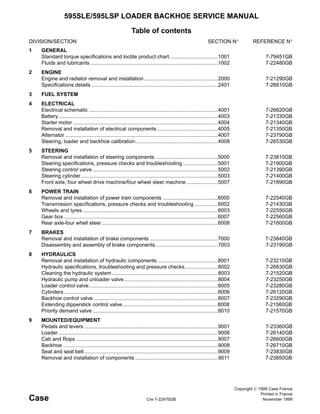
  • 9. 2000-6 Cre 7-21290GB Issued 10-99 PERSPECTIVE VIEW CI98G505 21 16 28 2 1 8 16 15 2 12 4 3 25 26 22 27 25 26 22 21 23 20 24 5 17 19 7 6 9 17 18 10 15 14 11 16 13 1. Hose 2. Collar 3. Hose 4. Collar 5. Seal 6. Shroud 7. Radiator 8. Cap, filler 9. Cooler, oil 10. Bracket 11. Nut 12. Screw 13. Washer 14. Stanchion 15. Washer 16. Nut 17. Bracket 18. Bracket 19. Collar 20. Nut 21. Hose 22. Clamp 23. Tank, expansion 24. Bracket 25. Screw 26. Washer 27. Plug 28. Grommet
  • 10. 2000-7 Cre 7-21290GB Issued 10-99 ENGINE REMOVAL Put identification tags on all disconnected hoses and wires. Close disconnected hoses and fittings with caps and plugs. STEP 1 Remove the radiator see page 4. STEP 2 Disconnect the battery. STEP 3 CI98G518 Remove the hose clip (4) from the air filter hose (5) at the turbocharger inlet. STEP 4 Support the air filter assembly (1) and remove the three bolts (2) from the cylinder head and two bolts (3) from the exhaust bracket. Remove the air filter assembly. 5 4 3 1 2 2 STEP 5 789M257A 789M256A Install the engine lifting bracket (6) using two of the bolts (2) from the air filter bracket. The bracket is part of the machine tool kit. 6 2 2 6
  • 11. 2000-8 Cre 7-21290GB Issued 10-99 STEP 6 CI98G519 Release the spring (1) and remove the exhaust pipe (2). STEP 7 Release the clip (3) on the silencer to turbocharger connection and remove the nuts, washers and spac- ers (4). Remove the silencer (5) from the bracket (6). STEP 8 Remove the three bolts and washers (7) from the exhaust bracket and remove the bracket. STEP 9 Remove the hydraulic oil pump drive shaft (see sec- tion 8004). 6 3 5 7 2 1 4 STEP 10 789M259A Disconnect the throttle cable (15) from the fuel injec- tion pump lever (14) and the bracket (16). STEP 11 789M287A Release the hose clips (19) on the heater hoses (17) at the thermostat housing (18). Remove the hoses and tie back under the scuttle. 14 16 15 14 15 16 19 18 17 17 18 19
  • 12. 2000-9 Cre 7-21290GB Issued 10-99 STEP 12 789M261A Remove the four bolts (20) in the hydraulic pump drive coupling (21) and remove the drive shaft (22). STEP 13 789M262A Release the hose clips (24) on the transmission filler flexible pipe (26), remove the two bolts and nuts (23) and (28) in the support bracket (27) and the nut and bolt (29) and (30) in the dipstick pipe support. 22 21 20 22 20 21 29, 30 28 27 26 25 23 24 24 23 30 29 28 27 26 25 STEP 14 Release the dipstick pipe coupling (25) on the trans- mission and remove the dipstick assembly. STEP 15 789M263A Remove the nut (32) from the wiring cover (31) on the starter motor (33) and remove the cover. STEP 16 789M264A Remove the bolt and nut (36) in the clip (35) for the transmission oil cooler pipe (34), and release the pipe. 33 32 31 33 31 32 35 36 34 35 36 34
  • 13. 2000-10 Cre 7-21290GB Issued 10-99 STEP 17 Disconnect and tag all wiring connections from the engine. These include the starter motor, the alterna- tor, the water temperature switch, the oil pressure switch, the thermostat unit, the air filter restriction switch and the fuel injection pump stop solenoid. STEP 18 789M265A Remove the front floor mat (37) in the cab. Remove the four screws (39) from the centre front floor plate (38) and remove the plate. STEP 19 CI98G501 Remove the six screws (41) from the gear lever tower (40) and slide the tower up the lever (42). 39 38 37 37 39 38 44 43 46 40 41 42 45 STEP 20 Remove the six screws (41) from the gear lever tower (40) and slide the tower up the lever (42). STEP 21 Disconnect the clutch switch wiring connection (44) and remove the spring (46) from the shift lever. STEP 22 Remove the bolt and nut (43) and (45) from the shift lever and remove the lever from the transmission. STEP 23 Put the wiring ties which attach the electrical harness to the support rail at the rear of the engine. STEP 24 Release the oil cooler hose clamp on the right hand side of the chassis. STEP 25 789M288A Disconnect the fuel inlet and discharge pipe (47) and (48) from the fuel lift pump. 48 47 48 47
  • 14. 2000-11 Cre 7-21290GB Issued 10-99 STEP 26 789M270A Remove the four bolts (52) and the two bearing caps (51) from the rear coupling. Lower the propshaft (49). Make sure that the needle roller bearing cups (50) on the rear coupling are taped to the joint. STEP 27 789M271A Remove the four bolts (54) and the inspection plate (55) from the bottom of the bell housing (53). 52 51 50 49 50 52 51 49 53 54 55 54 55 53 STEP 28 789M272A Remove the eight flywheel to torque converter bolts (56) and the washers (57) from the flex plate assem- bly (58). STEP 29 789M273A Remove all except two of the spacer housing bolts (59). 58 56,57 56, 57 57 56 57 56 58 59 59
  • 15. 2000-12 Cre 7-21290GB Issued 10-99 STEP 30 Position a trolley jack under the transmission, next to the front axle drive coupling flange. Raise the jack into contact with the transmission but DO NOT lift the transmission. STEP 31 Attach the special lifting bracket to the engine. STEP 32 789M256A Using a suitable hoist attached to the lifting bracket, apply tension to the lift chains. DO NOT raise the engine. STEP 33 789M257A Loosen the two bolts (62) and the nuts (60) from each engine bracket (61). 62 61 60 60 61 62 STEP 34 789M276A Remove the centre bolt (67), the nuts (64) and the washers (63) and (66) from each transmission mounting plate (65). STEP 35 Remove the rear propshaft. STEP 36 Using the hoist and trolley jack, raise the engine/ transmission unit sufficient to remove the engine mountings. (approximately 40 mm (1.5 in)). STEP 37 Lower the engine/transmission unit and move it towards the rear of the machine until the rear prop- shaft slicing joint is completely closed. STEP 38 Remove the two bolts in the spacer housing. 65 63 64 66 67 66 67 64 63 65
  • 16. 2000-13 Cre 7-21290GB Issued 10-99 STEP 39 Hold the transmission to the rear, and move the engine forward on the hoist to disengage the torque converters spigot. Make sure that the torque con- verter does not disengage from the transmission input shaft when the engine moves forward. STEP 40 Remove the engine from the machine. Installation NOTE : Install the engine in the reverse order of the removal but note the following : 1. 789M277A Before installation of the engine, make sure that the torque converter is correctly installed in the transmis- sion. The flex plate face (68) must be at least 50 mm (2.0 in) from the transmission flywheel cover face (69) (measurement A). If the measurement A is 40 mm (1.5 in) or less, the torque converter is not cor- rectly installed and must be removed and installed correctly. 2. During assembly of the engine to the transmis- sion, make sure that the torque converter spigot enters the fly wheel bush correctly. To check, rotate the torque converter as the engine and transmission come together. A 69 68 69 68 3. Torque tighten attaching parts as follows : Flywheel to torque converter flexible plate bolts..................................28 Nm (21 lbf ft) Rear coupling bearing cap bolts 37 Nm (27 lbf ft) Coupling flange bolts.................48 Nm (35 lbf ft) Starter motor friction nuts..........36 Nm (26 lbf ft) 4. Before starting the engine, do steps 3 through 8. 5. Bleed air from fuel system (see section 3410). 6. Check the transmission oil level (see section 6002). 7. Check the engine oil level. 8. Replenish the radiator and header tank with coolant. 9. Check the hydraulic oil level. 10. Carry out a complete functional test of the machine. Check all connections and joints for leakage. Check all fluid levels with the engine stopped and cold.
  • 17. 4004-3 Cre 7-21340GB Issued 10-99 Special tools 0 - 20 V DC voltmeter 0 - 150 A ammeter Mechanical tachometer 0 - 10,000 rev/min. Tightening Torques Nm lbf ft Solenoid main ‘BAT’ terminal M8 stud 6.0 4.5 Cable fixing nut M10 stud 12.0 9.0 Solenoid terminal M8 nut 6.0 4.5 Solenoid terminal M10 nut 12.0 9.0 Starter terminal 1/4 BSF nut 4.0 3.0 Solenoid end-cover screws 2.0 1.5 Solenoid unit screws 6.0 4.5 Brush-plate screws 7.0 5.0 Starter earth nuts 8.0 6.0 Pole shoes fixing screws 41.0 30 Through bolts 11.0 8.0 Eccentric pivot pin lock-nut 20.0 15.0 Specifications Pilot diameter 12.71 mm (0.5 in) Light running speed 5500 - 8000 rev/min. Light running current/voltage 115A at 11V Pinion end clearance when engaged 0.13 - 1.14 mm (0.005-0.045 in) New brush length 28.51 mm (1.226 in) Renew brushes at 8 mm (0.3 in) Spring pressure in workint 11.6 N (42 oz.) position with new brushes
  • 18. 4004-4 Cre 7-21340GB Issued 10-99 Removing and installing the starter motor Removing the starter motor Remove the starter motor as follows: 1. Disconnect the battery see section 4003. NOTE : Make sure the key is removed from the start switch on the side console. 2. Open the hood. 3. Remove the protective cover (13), the nut (12) and the cover (14) from the solenoid (4). 4. Note the installed positions of the electrical cables (9) and (17). 5. Remove the nut (11), the washer (10) and dis- connect the four electrical cables (9) from the starter motor (8). 6. Remove the two nuts (15), the two washers (16) and disconnect the three electrical cables (17) from the solenoid (4). 7. Attach the electrical cables (9) and (17) to the structure of the engine with temporary ties. 8. Support the starter motor (8) and solenoid (4). Remove the three nuts (7) and the “P-clip” mounting bracket (6) from the studs (5). 9. Slide the starter motor (8) together with the sole- noid (4) from the studs (5) and remove from the engine. 10. Put a warning sign in the cab to tell persons not to start the engine. Installing the starter motor NOTE : The installation of the starter motor is the reverse of the removal. Install the starter motor in the reverse order of the removal but note the following: 1. Torque tighten the nuts (12): 12 Nm. 2. Torque tighten the nut (11): 6 Nm. 3. After installation do the following tests: • The battery voltage under load test, refer to page 7. • The starter motor terminal voltage under load test, refer to page 8. • The voltage drop on the insulated line test, refer to page 8. • The voltage drop across solenoid contact refer to page 9. The voltage drop in earth line test, refer to page 10.
  • 19. 4004-5 Cre 7-21340GB Issued 10-99 789M048A
  • 20. 4004-6 Cre 7-21340GB Issued 10-99 Disassembling the starter motor Disassemble the starter motor as follows: 1. Remove the starter motor, refer to page 4. 2. Remove the solenoid assembly, refer to page 14. 3. Remove the end-cover, refer to page 12 (steps 3 through 6). 4. Remove the field winding brushes (10) from brush plate. 5. Remove the rubber grommet (13). 6. Slacken the locknut and remove the pivot pin (4). (The pivot is eccentric to the screw thread to allow adjustment of the pinion gear end-clear- ance). 7. Remove housing (2) and the pinion engagement lever (1). 8. Remove the armature and pinion assembly (9) from the motor body. 9. Use a suitable tube to punch the thrust-collar (6) towards the pinion and expose the snap-ring (5). 10. Remove the snap-ring (5). 11. Remove the thrust-collar (6). 12. Pull the pinion and the roller clutch (7), off the armature shaft. 13. Pull the intermediate plate (8) off the armature shaft. 14. Remove the four screws (11) and carefully pull the field windings (12) from the motor body. 15. Inspect and test the starter motor, refer to page 14. Assembling the starter motor NOTE : The assembly of the starter motor is the reverse of the disassembly. Assemble the starter motor in the reverse order of the disassembly but note the following: 1. Apply Shell Retinax “A” grease or its equivalent onto the drive shaft splines, the thrust-collar (6) and the engagement lever (1). 789M049A
  • 21. 4004-7 Cre 7-21340GB Issued 10-99 Adjusting the pinion stroke Adjust the pinion stroke as follows: 1. Remove the starter motor, refer to page 4. 2. Screw the pivot pin (B) fully into the casting and then slacken off one full turn and position the marks on the head as shown. 3. Connect the solenoid to a 6V supply as shown, which will operate the solenoid only. 4. While the solenoid is energized push the pinion lightly, back against the yoke, to eliminate any free play and measure the gap between the pin- ion end face and the snap ring collar. 5. If necessary, turn the pivot pin (8) to obtain a clearance of 0.13 to 1.14 mm (0.005 to 0.045 in). 6. Tighten the locknut to 20 Nm (15 lbf ft). 7. Install the starter motor, refer to page 4. Key A STARTER SWITCH B PIVOT PIN 789M051A Testing the battery voltage under load Test equipment 0 to 20 V dc voltmeter NOTE : This test can be made with the starter motor still installed on the machine. Do the battery voltage under load test as follows: 1. Check condition of battery or batteries, refer to page 9. 2. Open the hood. 3. Disconnect the wire from fuel injection pump to prevent the engine from starting. 4. Connect the voltmeter across the terminals as shown and with the engine fuel supply cut off, operate the starter. 5. The voltmeter should read approximately 9 V. A low voltage reading indicates excessive current flow in the circuit due to low resistance. 6. Reconnect the wire to the fuel injection pump if no further tests are required. 7. Close the hood. 789M052A
  • 22. 4004-8 Cre 7-21340GB Issued 10-99 Testing the starter motor terminal voltage under load Test equipment 0 to 20 V dc voltmeter NOTE : This test can be made with the starter motor still installed on the machine. Do the starter motor terminal voltage under load test as follows: 1. Open the hood. 2. Remove the protective cover (13), the nut (12) and the cover (14), refer to page 4. 3. Disconnect the wire from the fuel injection pump, to prevent the engine from starting. 4. Connect the voltmeter between the starter input terminal and earth (end bracket). Crank the engine with the fuel cut off. The voltmeter read- ing should not be more than 0.5 V lower than in the battery voltage under load test, refer to page 7. 5. A low reading (more than 0.5 V difference between tests 1 and 2) indicates high resistance in cables or contacts. 6. High readings indicate high resistance in the starter motor itself. 7. Reconnect the wire to fuel injection pump if no further tests are required. 8. Install the cover (14), the nut (12) and the pro- tective cover (13), refer to page 4. 9. Close the hood. 789M053A Testing the voltage drop on the insulated line Test equipment 0 to 20 V dc voltmeter NOTE : This test can be made with the starter motor still installed on the machine. Do the voltage drop on the insulated line as follows: 1. Open the hood. 2. Connect the voltmeter between the starter termi- nal and the battery terminal. 3. When the starter switch is open, the voltmeter should register battery voltage. When the starter switch is closed, the voltmeter should read prac- tically zero. 4. A high voltmeter reading indicates a high resis- tance in the starter circuit. Check all the insu- lated connections. 5. Do the voltage drop across the solenoid con- tacts test, refer to page 9. 789M054A
  • 23. 4004-9 Cre 7-21340GB Issued 10-99 Testing the voltage drop across the sole- noid contacts Test equipment 0 to 20 V dc voltmeter NOTE : This test can be made with the starter motor still installed on the machine. Do the voltage drop across the solenoid contacts test as follows: 1. Remove the protective cover (13), the nut (12) and the cover (14), refer to page 4. 2. Connect the voltmeter across the two main sole- noid terminals. 3. When the starter switch is open, the voltmeter should register battery voltage. When the starter switch is closed the reading should be zero or fractional value. 4. A zero or fractional reading indicates that the high resistance deduced in the voltage drop on the insulated line test must be due either to high resistance in the starter cables or soldered con- nections. A high reading (similar to the voltage drop on the insulated line test) indicates a faulty solenoid or connection, refer to page 8. 5. Install the cover (14), the nut (12) and the pro- tective cover (13), refer to page 4. 6. Close the hood. Key A STARTER SWITCH B TACHOMETER POSITION 789M055A
  • 24. 4004-10 Cre 7-21340GB Issued 10-99 Testing the voltage drop in earth line Test equipment 0 to 20 V dc voltmeter NOTE : This test can be made with the starter motor still installed on the machine. Do the voltage drop in earth line test as follows: 1. Open the hood. 2. Connect the voltmeter between the battery earth terminal and the starter earth (commutator end bracket). 3. When the starter switch is closed the voltmeter should read practically zero. 4. If reading is high, clean and tighten all earth con- nections and check bonding strap. 5. Close the hood. 789M056A Testing the no-load current and speed Test equipment Test bench Mechanical tachometer 0 to 10,000 rpm Ammeter up to 150 A capacity Do the no-load current and speed test as follows: 1. If necessary, remove the starter motor from the machine, refer to page 4. 2. Connect an ammeter in circuit between the starter solenoid and battery. 3. Hold the tachometer against the end of the pin- ion shaft and operate the starter switch. 4. Max. current: 115 A at 11 V. Max. speed: 5500 to 8000 rpm. Excess current indicates that starter is faulty. 5. If low current is registered, do the continuity of contacts test, refer to page 11. 6. If starter fails to operate and there is no audible operation of solenoid, then connect the ammeter across the “STA” terminal and the battery. Key A STARTER SWITCH B TACHOMETER POSITION 789M057A 7. Operate the starter switch, the starter motor should run, indicating a faulty solenoid which must be replaced. 8. If the starter motor does not run, the motor itself is faulty. 9. If the starter motor fails to operate but the sole- noid operation is audible, do the continuity of contacts test, refer to page 11.
  • 25. 4004-11 Cre 7-21340GB Issued 10-99 Testing the continuity of contacts Test equipment 0 to 20 V dc voltmeter Test the continuity of contacts as follows: 1. Open the hood. 2. Remove the protective cover (13), the nut (12) and the cover (14), refer to page 4. 3. Connect the voltmeter between motor and sole- noid negative terminals and operate starter switch. 4. No voltage indicates a faulty solenoid. Replace the solenoid, refer to page 14. 789M058A 5. 12 V registered but motor fails to operate indi- cates faulty motor. Replace the starter motor, refer to page 4. 6. 12 V registered and motor operates, test the voltage drop across the contacts, refer to page 11. Testing the voltage drop across the con- tacts Test equipment 0 to 20 V dc voltmeter Test the voltage drop across the contacts as follows: 1. Connect the voltmeter across the solenoid termi- nals and operate starter switch. 2. Voltage across the terminals should be zero, if more, the solenoid is faulty and must be changed, refer to page 13. 3. If solenoid is satisfactory, service the starter motor, refer to page 14. 789M059A
  • 26. 4004-12 Cre 7-21340GB Issued 10-99 Servicing the end cover and brush car- rier Service the end cover and brush carrier as follows: 1. Open the hood. NOTE : If space within the engine compartment per- mits the removal of the motor body bolts (3), the end cover can be serviced without removing the starter motor from the engine, provided that the electrical cables to the starter are disconnected. 2. If the end cover cannot be removed in situ, remove the starter motor, refer to page 4. 3. Remove the end cover securing screws (2), and both long bolts (3). 4. Lift off the cover (4) complete with brake assem- bly. 5. Remove the brake shoes (5) from the cover (4). 6. Remove the steel washer (6) and fibre washer (7). 7. Lift the springs and disengage the field coil brushes (8). 8. Remove the brush carrier assembly (9). 9. Polish the commutator with 600 to 1200 grade abrasive cloth/paper. 10. Thoroughly clean all components with white spirit and dry with compressed air. 11. Measure the length of the brushes (8). Replace the brushes which are 8 mm (5/16 in) or less in length, refer to page 13. 12. Install the brush carrier assembly (9). 789M060A 789M061A 13. Lift the springs and engage the brushes (8). 14. Test the strength of each brush spring and replace any which exert less than 11.6 N (42 oz.) with new brushes fitted. 15. Install the fibre washer (7), the steel washer (6) and the brake shoes (5) in the cover (4). 16. Turn the armature to position to drive-dogs (10) to engage the brake shoes (5). 17. Install the cover (4), the long bolts (3) and the screws (2). 18. Torque tighten the long bolts (3) to 11 Nm (8 lbf ft). 19. Check the clearance between the armature spindle and the brush (1). If the clearance is noticeable, replace the brush (1), refer to page 13. 20. If necessary, install the starter motor, refer to page 4. 21. Close the hood.
  • 27. 4004-13 Cre 7-21340GB Issued 10-99 Replacing the starter motor brushes Replace the brushes as follows: 1. Gain access to the brushes, refer to page 12 (steps 1 through 10). 2. On earth brushes, cut the flexible wires adjacent to the old brushes (1) and solder new brushes on to the flexible wires. 3. On insulated brushes, cut the flexible wires adja- cent to the old brushes (1). Open the eyelet on the new brush. Apply a thin coat of solder and crimp the eyelet onto the flexible wire and solder together. 4. Install the cover, refer to page 12 (steps 12 through 21). 789M062A Replacing the bushes in the starter motor Replace the bushes in the starter motor as follows: 1. Gain access, as necessary to the bush (1), (3) or (5) to be replaced, refer to page 6 or page 12. 2. If the bush (5) in the end cover (6) is to be replaced, remove the bush (5) using a 9/16 in, Whitworth tap. 3. If the bush (1) in the intermediate plate (4) is to be replaced, remove the bush (1) using a drift with a pilot diameter of 28.51 mm (1.226 in). 4. If the bush (3) in the housing (2) is to be replaced, remove the bush (3) using a drift hav- ing a pilot diameter of 17.03 mm (0.6705 in). 5. Immerse the replacement bush (1), (3) or (5) in clean engine oil for 24 hours. NOTE : The oil absorption time can be reduced by heating the oil to 100°C (212°F) for 2 hours and allowing it to cool before removing the brush. A ther- mometer is essential to prevent overheating the oil. 6. Install the bush (5) into the end cover (6) using a drift having a pilot diameter of 12.71 mm (0.5 in). 7. Install the bush (1) into the intermediate plate (4) using a drift having a pilot diameter of 28.51 mm (1.226 in). 8. Install the bush (3) into the housing (2) using a drift having a pilot diameter of 17.03 mm (0.6705 in). 9. Assemble the starter motor as necessary, refer to page 6 or 12. 789M353A
  • 28. Suggest: If the above button click is invalid. Please download this document first, and then click the above link to download the complete manual. Thank you so much for reading
  • 29. 4004-14 Cre 7-21340GB Issued 10-99 Removing the starter motor solenoid Remove the starter motor solenoid as follows: 1. Remove the starter motor, refer to page 4. 2. Remove the two nuts (3) and the copper link (4). 3. Remove the two nuts (1) which secure the sole- noid (5) to the starter motor (2). 4. Remove the solenoid body (5). 5. Remove the solenoid plunger from the engage- ment lever. 789M064A Installing the starter motor solenoid NOTE : The installation of the starter motor solenoid is the reverse of the removal. Install the starter motor solenoid in the reverse order of the removal but note the following: 1. Torque tighten the nuts (1), refer to page 3. 2. Torque tighten the nuts (3), refer to page 3. Inspecting and testing the starter motor Test equipment 110 volt insulation tester or ohmmeter Inspect and test the starter motor as follows: 1. Inspect the bush (7) in the alternator cap (8). If the clearance between the bush (7) and the shaft (6) is noticeable, replace the bush (7), refer to page 13. 2. Partially disassemble the starter motor, refer to page 6 (steps 1 through 6). 3. Inspect the bush (3) in the drive housing (2). If the clearance between the bush (3) and the shaft (4) is noticeable, replace the bush (3), refer to page 13. 4. Continue to disassemble the starter motor, refer to page 6 (steps 7 through 12). 5. Inspect the bush (1) in the intermediate plate (5). If the clearance between the bush (1) and the shaft (4) is noticeable, replace the bush (1), refer to page 13. 6. Complete the disassembly of the starter motor, refer to page 6 (steps 13 and 14). 7. Use a 110 V insulation tester or ohmmeter, to check the insulation of the electrical components (steps 8 through 10). 8. Touch one test probe (9) onto an insulated brush holder and the other (10) on an unpainted part of the carrier plate, refer to page 15. The ohmmeter must read infinity, as no current should pass between the probes. If the meter reads less than infinity, replace the brush holder. 9. Touch one probe (11) on the field terminal, the other (12) on a clean part of the motor body, but ensure neither brush touches the body, refer to page 15. The ohmmeter must read infinity, if the meter indicates less than infinity the field coils are shorting and must be replaced. 10. Touch one probe (14) onto the armature shaft, the other probe (13) onto a commutator seg- ment, refer to page 15. The ohmmeter must read infinity. If the meter indicates less than infinity, the armature must be replaced. 11. Assemble the starter motor, refer page 6. WARNING : Only trained electrical personnel must do these checks. !