
Recommended
Recommended
More Related Content
What's hot
What's hot (11)
More from jksmemmd
More from jksmemmd (15)
LIEBHERR R954C LITRONIC HYDRAULIC EXCAVATOR Service Repair Manual
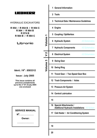
- 1. 1 General Information 2 Tools 3 Technical Data / Maintenance Guidelines 4 Engine 5 Coupling / Splitterbox 6 Hydraulic System A3 Schematics MJFCIFSS! HYDRAULIC EXCAVATORS R 954 / R 954 B / R 954 C R 964 / R 964 B R 974 B R 984 B / R 984 C 7 Hydraulic Components A3 Schematics 8 Electrical System A3 Schematics 9 Swing Gear 10 Swing Ring 11 Travel Gear / Two Speed Gear Box 12 Track Components / Axles 13 Pressure Air System 14 Central Lubrication 15 16 Special Attachments / Additional Hydraulic Installations A3 Schem 17 Cab Heater / Air Conditioning System 19 Ident. / Nb : 8503312 Issue : July 2005 This issue contains all previous complements up to the nb 07 of july 2005 one enclosed 20 SERVICE MANUAL Nb . ..................... Owner: ..........................
- 2. Service Manual Hydraulic Excavator Table of contents Group modified new date Group modified new date Pages nb pages pages of issue Pages nb pages pages of issue R 954 - R 954 B R 964 - R 964 B LIEBHERR 00-01 R 974 B R 984 B - R 984 C Date: 07 / 2005 00.10.01 & 02 ............... ...................... .............10.01 01.00.01........................ ...................... .............02.03 01.01.01........................ ...................... .............05.00 01.10.01 & 02 ............... ...................... .............09.01 01.10.03 & 04 ............... ...................... .............09.01 01.10.05 & 06 ............... ...................... .............09.01 01.10.07 & 08 ............... ...................... .............09.01 01.10.09 & 10 ............... ...................... .............09.01 01.19.01........................ ...................... .............09.01 01.20.01 & 02 ............... ...................... .............09.01 01.20.03 & 04 ............... ...................... .............09.01 01.20.05...................... X ..................... .............03.04 01.30.01 & 02 ............... ...................... .............11.92 01.40.01 & 02 ............... ...................... .............10.96 01.40.03 & 04 ............... ...................... .............10.96 01.40.05 & 06 ............... ...................... .............10.96 01.50.01 & 02 ............... ...................... .............09.99 01.50.03 & 04 ............... ...................... .............09.99 01.50.05 & 06 ............... ...................... .............09.99 01.50.07 & 08 ............... ...................... .............09.99 01.50.09 & 10 ............... ...................... .............06.00 Suppress the existing group 02. 02.00.01 & 02 ............... .................... X ............06.03 02.01.01 & 02 ............... .................... X ............06.05 02.01.03 & 04 ............... .................... X ............06.05 02.01.05 & 06 ............... .................... X ............06.05 02.01.07 & 08 ............... .................... X ............06.05 02.01.09 & 10 ............... .................... X ............06.05 02.01.11 & 12 ............... .................... X ............06.05 02.01.13 & 14 ............... .................... X ............06.05 02.01.15 & 16 ............... .................... X ............06.05 02.01.17 & 18 ............... .................... X ............06.05 02.01.19 & 20 ............... .................... X ............06.05 02.02.01 & 02 ............... .................... X ............06.05 02.02.03 & 04 ............... .................... X ............06.05 02.02.05 & 06 ............... .................... X ............06.05 02.03.01 & 02 ............... .................... X ............06.05 02.03.03 & 04 ............... .................... X ............06.05 02.04.01 & 02 ............... .................... X ............06.05 02.04.03 & 04 ............... .................... X ............06.05 02.04.05 & 06 ............... .................... X ............06.05 02.05.01 & 02 ............... .................... X ............06.05 02.05.03 & 04 ............... .................... X ............06.05 02.06.01 & 02 ............... .................... X ............06.05 02.06.03 & 04 ............... .................... X ............06.05 02.06.05 & 06 ............... .................... X ............06.05 02.06.07 & 08 ............... .................... X ............06.05 02.06.09 & 10 ............... .................... X ............06.05 02.06.11 & 12 ............... .................... X ............06.05 02.07.01 & 02 ............... .................... X ............06.05 02.08.01 & 02 ............... .................... X ............06.05 02.09.01 & 02 ............... .................... X ............06.05 02.09.03 & 04 ............... .................... X ............06.05 02.09.05 & 06 ............... .................... X ............06.05 02.09.07 & 08 ............... .................... X ............06.05 02.09.09 & 10 ............... .................... X ............06.05 02.09.11 & 12 ............... .................... X ............06.05 02.09.13 & 14............... ..................... X ............06.05 02.09.15 & 16............... ..................... X ............06.05 02.09.17 & 18............... ..................... X ............06.05 02.09.19 & 20............... ..................... X ............06.05 02.09.21 & 22............... ..................... X ............06.05 02.09.23 & 24............... ..................... X ............06.05 02.09.25 & 26............... ..................... X ............06.05 02.09.27 & 28............... ..................... X ............06.05 02.09.29 & 30............... ..................... X ............06.05 02.09.31 & 32............... ..................... X ............06.05 02.09.33 & 34............... ..................... X ............06.05 02.09.35 & 36............... ..................... X ............06.05 02.09.37 & 38............... ..................... X ............06.05 02.09.39 & 40............... ..................... X ............06.05 02.09.41 & 42............... ..................... X ............06.05 02.09.43 & 44............... ..................... X ............06.05 02.09.45 & 46............... ..................... X ............06.05 02.09.47 & 48............... ..................... X ............06.05 02.09.49 & 50............... ..................... X ............06.05 02.09.51 & 52............... ..................... X ............06.05 02.09.53 & 54............... ..................... X ............06.05 02.09.55 & 56............... ..................... X ............06.05 02.09.57 & 58............... ..................... X ............06.05 03.00.00...................... X .................... ..............06.05 03.01.01 & 02............... ...................... ..............05.00 03.01.03 & 04............... ...................... ..............05.00 03.02.01 & 02............... ..................... X ............07.05 03.02.03....................... ..................... X ............07.05 03.03.01 & 02............... ...................... ..............05.00 03.03.11 & 12............... ..................... X ............06.04 03.03.13....................... ..................... X ............06.04 03.04.01 & 02............... ..................... X ............07.05 03.04.03....................... ..................... X ............07.05 03.05.01 & 02............... ...................... ..............05.00 03.05.11 & 12............... ..................... X ............06.04 03.05.13....................... ..................... X ............06.04 03.06.01 & 02............... ..................... X ............07.05 03.06.03....................... ..................... X ............07.05 03.07.01 & 02............... ...................... ..............05.00 03.11.01 & 02............... ...................... ..............04.94 03.11.03 & 04............... ...................... ..............05.98 03.12.01 & 02............... ..................... X ............04.05 03.12.03 & 04............... ..................... X ............04.05 03.13.01 & 02............... ...................... ..............04.94 03.13.03 & 04............... ...................... ..............08.99 03.13.11 & 12............... ..................... X ............06.04 03.13.13 & 14............... ..................... X ............06.04 03.15.01 & 02............... ...................... ..............08.99 03.16.01 & 02............... ..................... X ............06.04 03.16.03 & 04............... ..................... X ............06.04 03.17.01 & 02............... ...................... ..............06.95 03.31.01....................... ...................... ..............04.00 03.33.01....................... ...................... ..............06.95 03.33.03....................... ...................... ..............04.00 03.35.01....................... ...................... ..............04.00 03.37.01....................... ...................... ..............04.00
- 3. Service Manual Hydraulic Excavator Table of contents Group modified new date Group modified new date Pages nb pages pages of issue Pages nb pages pages of issue R 954 - R 954 B R 964 - R 964 B LIEBHERR 00-02 R 974 B R 984 B - R 984 C Date: 07 / 2005 04.00.01........................ ...................... .............02.03 04.10.01 & 02 ............... ...................... .............08.96 04.10.03 & 04 ............... ...................... .............02.93 04.20.01 & 02 ............... ...................... .............11.99 04.20.03 & 04 ............... ...................... .............09.96 04.20.11 & 12 ............... ...................... .............02.97 04.20.13 & 14 ............... ...................... .............02.97 04.21.01........................ ...................... .............07.97 04.23.01........................ ...................... .............06.00 04.23.03 & 04 ............... ...................... .............06.00 04.23.05 & 06 ............... ...................... .............06.00 04.23.07 & 08 ............... ...................... .............06.00 04.23.09 & 10 ............... ...................... .............06.00 04.23.11 & 12 ............... ...................... .............06.00 04.23.13 & 14 ............... ...................... .............06.00 04.23.15 & 16 ............... ...................... .............06.00 04.23.17 & 18 ............... ...................... .............06.00 04.23.19 & 20 ............... ...................... .............06.00 04.23.21 & 22 ............... ...................... .............06.00 04.23.23 & 24 ............... ...................... .............06.00 04.23.25 & 26 ............... ...................... .............06.00 04.23.27........................ ...................... .............06.00 04.23.29........................ ...................... .............06.00 04.30.01 & 02 ............... ...................... .............02.93 04.35.01 & 02 ............... ...................... .............02.93 04.36.01........................ ...................... .............02.03 04.50.01 & 02 ............... ...................... .............02.93 04.50.03 & 04 ............... ...................... .............02.93 04.50.05 & 06 ............... ...................... .............02.93 05.00.00........................ ...................... .............06.98 05.10.01 & 02 ............... ...................... .............11.92 05.20.01 & 02 ............... ...................... .............02.93 05.20.03 & 04 ............... ...................... .............06.98 05.20.05........................ ...................... .............06.98 05.21.01 & 02 ............... ...................... .............02.93 05.21.03 & 04 ............... ...................... .............02.93 05.21.05 & 06 ............... ...................... .............06.98 05.21.07........................ ...................... .............06.98 05.31.01 & 02 ............... ...................... .............06.98 05.31.03 & 04 ............... ...................... .............06.98 05.31.05........................ ...................... .............06.98 06.00.01 & 02 ............. X ..................... .............10.04 06.03.01........................ ...................... .............02.93 06.05.01 & 02 ............... ...................... .............05.93 06.07.01 & 02 ............... ...................... .............09.96 06.09.01 & 02 ............... ...................... .............06.00 06.09.03 & 04 ............... ...................... .............06.00 06.10.01 & 02 ............... ...................... .............10.02 06.10.03........................ ...................... .............10.02 06.11.01 & 02 ............... ...................... .............10.02 06.11.03 & 04 ............... ...................... .............10.02 06.12.01 & 02 ............... ...................... .............10.02 06.12.03 & 04 ............... ...................... .............10.02 06.12.05........................ ...................... .............10.02 06.13.01 & 02 ............... .................... X ............06.05 06.13.03 & 04 ............... .................... X ............06.05 06.13.05....................... ..................... X ............06.05 06.14.01 & 02............... ...................... ..............10.02 06.14.03 & 04............... ...................... ..............10.02 06.15.01 & 02............... ...................... ..............10.02 06.15.03 & 04............... ...................... ..............10.02 06.15.05....................... ...................... ..............10.02 06.16.01 & 02............... ..................... X ............06.04 06.16.03 & 04............... ..................... X ............06.04 06.16.05....................... ..................... X ............06.04 06.17.01 & 02............... ...................... ..............02.96 06.17.03....................... ...................... ..............06.96 06.18.01 & 02............... ...................... ..............10.02 06.18.03 & 04............... ...................... ..............10.02 06.18.05....................... ...................... ..............10.02 06.18.11 & 12............... ..................... X ............06.04 06.18.13 & 14............... ..................... X ............06.04 06.18.15....................... ..................... X ............06.04 06.19.01 & 02............... ...................... ..............11.00 06.19.03 & 04............... ...................... ..............11.00 06.20.01 & 02............... ...................... ..............10.02 06.20.03 & 04............... ...................... ..............10.02 06.20.05 & 06.............. X .................... ..............01.05 06.31.01 & 02............... ...................... ..............02.93 06.31.03 & 04............... ...................... ..............02.93 06.31.05 & 06............... ...................... ..............02.93 06.31.07 & 08............... ...................... ..............02.93 06.31.09....................... ...................... ..............02.93 06.34.01 & 02............... ...................... ..............02.93 06.34.03 & 04............... ...................... ..............02.93 06.34.05 & 06............... ...................... ..............02.93 06.34.07 & 08............... ...................... ..............02.93 06.34.09 & 10............... ...................... ..............04.93 06.34.11....................... ...................... ..............02.93 06.36.01 & 02............... ...................... ..............04.93 06.36.03 & 04............... ...................... ..............03.93 06.36.05 & 06............... ...................... ..............04.93 06.36.07 & 08............... ...................... ..............04.93 06.36.09 & 10............... ...................... ..............04.93 06.36.11 & 12............... ...................... ..............02.93 06.38.01 & 02............... ...................... ..............02.93 06.38.03 & 04............... ...................... ..............02.93 06.38.05 & 06............... ...................... ..............04.93 06.38.07 & 08............... ...................... ..............02.93 06.38.09 & 10............... ...................... ..............02.93 06.38.11 & 12............... ...................... ..............11.96 06.39.01 & 02............... ...................... ..............04.93 06.39.03 & 04............... ...................... ..............04.93 06.39.05 & 06............... ...................... ..............04.93 06.40.01 & 02............... ...................... ..............07.97 06.40.03 & 04............... ...................... ..............07.97 06.40.05 & 06............... ...................... ..............07.97 06.40.07 & 08............... ...................... ..............07.97 06.40.09 & 10............... ...................... ..............10.99 06.41.01 & 02............... ...................... ..............12.96 06.41.03 & 04............... ...................... ..............01.97 06.42.01 & 02............... ...................... ..............01.98 06.42.03 & 04............... ...................... ..............01.98 06.42.05 & 06............... ...................... ..............10.02
- 4. Service Manual Hydraulic Excavator Table of contents Group modified new date Group modified new date Pages nb pages pages of issue Pages nb pages pages of issue R 954 - R 954 B R 964 - R 964 B LIEBHERR 00-03 R 974 B R 984 B - R 984 C Date: 07 / 2005 06.42.11 & 12 ............... ...................... .............10.02 06.42.13 & 14 ............... ...................... .............10.02 06.42.21 & 22 ............... .................... X ............06.05 06.42.23........................ .................... X ............06.05 06.43.01 & 02 ............... ...................... .............05.93 06.43.03 & 04 ............... ...................... .............05.93 06.44.01 & 02 ............... ...................... .............07.97 06.44.03 & 04 ............... ...................... .............01.98 06.44.05 & 06 ............... ...................... .............05.98 06.44.11 & 12 ............... ...................... .............05.98 06.44.13 & 14 ............... ...................... .............05.98 06.44.21 & 22 ............... ...................... .............12.99 06.44.23 & 24 ............... ...................... .............10.02 06.44.31 & 32 ............... ...................... .............10.02 06.44.33 & 34 ............... ...................... .............10.02 06.44.41 & 42 ............... .................... X ............06.04 06.44.43 & 44 ............... .................... X ............06.04 06.45.01 & 02 ............... ...................... .............12.96 06.45.03 & 04 ............... ...................... .............12.96 06.45.05 & 06 ............... ...................... .............06.97 06.46.01 & 02 ............... ...................... .............10.02 06.46.03 & 04 ............... ...................... .............10.02 06.46.11 & 12 ............... .................... X ............06.04 06.46.13 & 14 ............... .................... X ............06.04 06.47.01 & 02 ............... ...................... .............12.99 06.47.03 & 04 ............... ...................... .............12.96 06.47.05 & 06 ............... ...................... .............01.97 06.47.07 & 08 ............... ...................... .............01.98 06.47.09 & 10 ............... ...................... .............05.98 06.47.11 & 12 ............... ...................... .............12.99 06.47.13 & 14 ............... ...................... .............07.99 06.48.01 & 02 ............... ...................... .............10.02 06.48.03 & 04 ............... ...................... .............10.02 06.48.05 & 06 ............... ...................... .............11.02 06.48.07 & 08 ............... ...................... .............02.03 06.48.09 & 10 ............... .................... X ............02.05 06.48.11 & 12 ............... .................... X ............02.05 06.58.01 & 02 ............... ...................... .............03.95 06.58.03 & 04 ............... ...................... .............07.97 06.58.05 & 06 ............... ...................... .............03.95 06.58.07 & 08 ............... ...................... .............03.95 06.58.09 & 10 ............... ...................... .............03.99 06.59.01 & 02 ............... ...................... .............03.95 06.59.03 & 04 ............... ...................... .............03.95 06.59.05 & 06 ............... ...................... .............03.95 06.70.01 & 02 ............... ...................... .............12.02 06.70.03 & 04 ............... ...................... .............12.02 06.71.01 & 02 ............... ...................... .............07.95 06.72.01 & 02 ............... ...................... .............12.99 06.73.01........................ .................... X ............10.04 Underlined pages are joined as A3 size at the end of each group 07.00.01 & 02 ............. X ..................... .............11.04 07.05.01........................ ...................... .............07.96 07.05.03 & 04 ............... ...................... .............07.96 07.05.05....................... ...................... ..............03.93 07.05.11 & 12............... ...................... ..............01.03 07.05.13 & 14............... ...................... ..............01.03 07.05.15 & 16............... ...................... ..............01.03 07.05.21 & 22............... ..................... X ............01.05 07.05.23 & 24............... ..................... X ............01.05 07.05.25....................... ..................... X ............01.05 07.06.01....................... ...................... ..............11.96 07.06.03 & 04............... ...................... ..............11.96 07.06.05....................... ...................... ..............11.96 07.06.11 & 12............... ...................... ..............01.03 07.06.13 & 14............... ...................... ..............01.03 07.06.15 & 16............... ...................... ..............01.03 07.07.01....................... ...................... ..............04.95 07.07.03 & 04............... ...................... ..............04.95 07.07.05....................... ...................... ..............04.95 07.07.11 & 12............... ...................... ..............01.03 07.07.13 & 14............... ...................... ..............01.03 07.07.15....................... ...................... ..............01.03 07.08.01....................... ...................... ..............04.95 07.08.03 & 04............... ...................... ..............06.00 07.08.05....................... ...................... ..............07.96 07.08.11 & 12............... ...................... ..............01.03 07.08.13 & 14............... ...................... ..............01.03 07.08.15....................... ...................... ..............01.03 07.10.01 & 02............... ...................... ..............03.93 07.10.03 & 04............... ...................... ..............03.93 07.10.05 & 06............... ...................... ..............03.93 07.10.07 & 08............... ...................... ..............03.93 07.10.09 & 10............... ...................... ..............03.93 07.10.11 & 12............... ...................... ..............03.93 07.10.13....................... ...................... ..............03.93 07.11.01 & 02............... ...................... ..............05.97 07.11.03 & 04............... ...................... ..............05.97 07.11.05 & 06............... ...................... ..............05.97 07.11.07 & 08............... ...................... ..............05.97 07.11.09 & 10............... ...................... ..............05.97 07.11.11....................... ...................... ..............10.99 07.12.01 & 02.. Suppress pages 07.13.01 & 02............... ...................... ..............12.97 07.13.03 & 04............... ...................... ..............12.97 07.13.05 & 06............... ...................... ..............12.97 07.14.01 & 02.............. X .................... ..............10.04 07.14.03 & 04.............. X .................... ..............10.04 07.14.05 & 06.............. X .................... ..............10.04 07.14.07 & 08.............. X .................... ..............10.04 07.14.09 & 10............... ..................... X ............10.04 07.15.01....................... ...................... ..............05.95 07.15.03 & 04............... ...................... ..............05.95 07.15.05 & 06............... ...................... ..............05.95 07.15.07 & 08............... ...................... ..............05.95 07.15.09....................... ...................... ..............05.95 07.15.11....................... ...................... ..............05.95 07.15.13 & 14............... ...................... ..............12.95 07.15.15 & 16............... ...................... ..............05.95 07.15.17....................... ...................... ..............05.95 07.17.01....................... ...................... ..............04.95 07.17.03 & 04............... ...................... ..............04.95
- 5. Service Manual Hydraulic Excavator Table of contents Group modified new date Group modified new date Pages nb pages pages of issue Pages nb pages pages of issue R 954 - R 954 B R 964 - R 964 B LIEBHERR 00-04 R 974 B R 984 B - R 984 C Date: 07 / 2005 07.17.05 & 06 ............... ...................... .............04.95 07.17.07 & 08 ............... ...................... .............04.95 07.17.09 & 10 ............... ...................... .............06.95 07.17.11 & 12 ............... ...................... .............04.95 07.17.13 & 14 ............... ...................... .............04.95 07.17.15 & 16 ............... ...................... .............04.95 07.18.01 & 02 ............. X ..................... .............01.05 07.18.03 & 04 ............. X ..................... .............01.05 07.18.05 & 06 ............. X ..................... .............01.05 07.18.07 & 08 ............... .................... X ............01.05 07.18.09 & 10 ............... .................... X ............01.05 07.18.11........................ .................... X ............01.05 07.19.01 & 02 ............... ...................... .............03.02 07.19.03 & 04 ............... ...................... .............03.02 07.19.05 & 06 ............... ...................... .............03.02 07.19.07........................ ...................... .............03.02 07.20.01 & 02 ............. X ..................... .............01.05 07.20.03 & 04 ............... .................... X ............01.05 07.21.01 & 02 ............... .................... X ............01.05 07.24.01........................ .................... X ............11.04 07.25.01 & 02 ............... ...................... .............02.97 07.25.03 & 04 ............... ...................... .............03.93 07.25.05 & 06 ............... ...................... .............03.93 07.28.01 & 02 ............... ...................... .............03.93 07.28.03 & 04 ............... ...................... .............03.93 07.28.05........................ ...................... .............03.93 07.29.01 & 02 ............... ...................... .............06.98 07.28.03 & 04 ............... ...................... .............06.98 07.28.05........................ ...................... .............06.98 07.30.01 & 02 ............... ...................... .............02.03 07.30.03 & 04 ............... ...................... .............02.03 07.30.05 & 06 ............... ...................... .............02.03 07.30.07 & 08 ............... ...................... .............02.03 07.30.09 & 10 ............... ...................... .............02.03 07.30.11........................ ...................... .............02.00 07.31.01 & 02 ............... ...................... .............02.03 07.35.01........................ ...................... .............02.03 07.36.01........................ ...................... .............02.03 07.37.01........................ ...................... .............02.03 07.38.01........................ ...................... .............02.03 07.41.01 & 02 ............... ...................... .............02.93 07.42.03........................ ...................... .............02.93 07.43.01 & 02 ............... ...................... .............09.99 07.43.03 & 04 ............... ...................... .............09.99 07.44.01 & 02 ............... ...................... .............02.93 07.44.03........................ ...................... .............02.93 07.47.01 & 02 ............... ...................... .............12.96 07.48.01 & 02 ............... ...................... .............06.97 07.49.01 & 02 ............... ...................... .............04.93 07.49.03........................ ...................... .............04.93 07.51.01 & 02 ............... ...................... .............11.96 07.51.03........................ ...................... .............11.96 07.52.01 & 02 ............... ...................... .............02.93 07.52.03........................ ...................... .............02.93 07.54.01 & 02 ............... ...................... .............03.93 07.54.03........................ ...................... .............03.93 07.60.01........................ ...................... .............01.03 07.61.01 & 02 ............... ...................... .............09.97 07.61.03 & 04............... ...................... ..............09.97 07.61.05 & 06............... ...................... ..............09.97 07.62.01 & 02............... ...................... ..............04.97 07.62.03 & 04............... ...................... ..............04.97 07.62.05 & 06............... ...................... ..............06.97 07.62.07 & 08............... ...................... ..............06.97 07.62.09 & 10............... ...................... ..............06.97 07.62.11 ....................... ...................... ..............02.93 07.63.01 & 02............... ...................... ..............05.98 07.63.03 & 04............... ...................... ..............06.97 07.63.05 & 06............... ...................... ..............05.97 07.63.07 & 08............... ...................... ..............06.97 07.63.09 & 10............... ...................... ..............01.03 07.63.11....................... ...................... ..............01.03 07.64.01 & 02............... ...................... ..............06.95 07.64.03 & 04............... ...................... ..............06.95 07.64.05 & 06............... ...................... ..............06.95 07.64.07 & 08............... ...................... ..............06.95 07.64.09 & 10............... ...................... ..............06.95 07.64.11 & 12............... ...................... ..............06.95 07.65.01 & 02............... ...................... ..............12.99 07.65.03 & 04............... ...................... ..............01.03 07.65.05....................... ...................... ..............12.99 07.67.01 & 02............... ...................... ..............06.95 07.67.03....................... ...................... ..............06.95 07.68.01 & 02............... ...................... ..............07.96 07.68.03....................... ...................... ..............07.96 07.69.01 & 02............... ...................... ..............01.96 07.69.03....................... ...................... ..............01.96 07.69.11 & 12............... ...................... ..............12.99 07.69.13....................... ...................... ..............12.99 07.71.01 & 02............... ...................... ..............03.93 07.74.01 & 02............... ...................... ..............03.93 07.74.03 & 04............... ...................... ..............03.93 07.81.01 & 02............... ...................... ..............10.92 07.85.01 & 02............... ...................... ..............10.92 07.87.01 & 02............... ...................... ..............10.92 07.89.01....................... ...................... ..............07.95 07.90.01 & 02............... ...................... ..............03.93 07.91.01....................... ...................... ..............11.92 07.92.01 & 02............... ...................... ..............05.93 07.97.01 & 02............... ...................... ..............03.93 07.98.01 & 02............... ...................... ..............10.01 07.98.03 & 04............... ...................... ..............10.01 Underlined pages are joined as A3 size at the end of each group 08.00.01...................... X .................... ..............06.05 08.10.01 & 02............... ...................... ..............02.97 08.10.03 & 04............... ...................... ..............03.93 08.10.05 & 06............... ...................... ..............03.93 08.10.07 & 08............... ...................... ..............03.93 08.10.09 & 10............... ...................... ..............03.93 08.10.11 & 12............... ...................... ..............04.00 08.10.13 & 14............... ...................... ..............03.93 08.10.15 & 16............... ...................... ..............03.93
- 6. Service Manual Hydraulic Excavator Table of contents Group modified new date Group modified new date Pages nb pages pages of issue Pages nb pages pages of issue R 954 - R 954 B R 964 - R 964 B LIEBHERR 00-05 R 974 B R 984 B - R 984 C Date: 07 / 2005 08.10.17 & 18 ............... ...................... .............02.97 08.10.19 & 20 ............... ...................... .............02.97 08.12.01 & 02 ............... ...................... .............05.00 08.12.03 & 04 ............... ...................... .............05.00 08.12.05 & 06 ............... ...................... .............06.00 08.12.07 & 08 ............... ...................... .............06.00 08.12.09........................ ...................... .............06.00 08.30.01........................ ...................... .............02.97 08.30.03 & 04 ............... ...................... .............03.93 08.30.05 & 06 ............... ...................... .............11.96 08.30.07 & 08 ............... ...................... .............11.96 08.30.11........................ ...................... .............02.97 08.30.13 & 14 ............... ...................... .............05.98 08.30.15 & 16 ............... ...................... .............11.96 08.30.17 & 18 ............... ...................... .............04.98 08.30.19........................ ...................... .............01.97 08.31.03 & 04 ............... ...................... .............05.00 08.31.05 & 06 ............... ...................... .............05.00 08.31.07........................ ...................... .............05.00 08.31.09........................ ...................... .............04.00 08.31.11........................ ...................... .............04.00 08.31.13........................ ...................... .............04.00 08.31.15........................ ...................... .............04.00 08.31.17........................ ...................... .............04.00 08.31.19........................ ...................... .............04.00 08.31.21........................ ...................... .............04.00 08.31.23........................ ...................... .............04.00 08.32.01 & 02 ............... ...................... .............09.02 08.32.03 & 04 ............... ...................... .............09.02 08.32.05 & 06 ............... ...................... .............09.02 08.32.07........................ ...................... .............10.02 08.32.09........................ ...................... .............10.02 08.32.11........................ ...................... .............10.02 08.32.13........................ ...................... .............10.02 08.32.15........................ ...................... .............10.02 08.32.17........................ ...................... .............10.02 08.32.19........................ ...................... .............10.02 08.32.21........................ ...................... .............10.02 08.33.01 & 02 ............... .................... X ............02.05 08.33.03 & 04 ............... .................... X ............02.05 08.33.05 & 06 ............... .................... X ............02.05 08.33.07........................ .................... X ............02.05 08.33.09 & 10 ............... .................... X ............07.05 08.33.11 & 12 ............... .................... X ............07.05 08.33.13 & 14 ............... .................... X ............07.05 08.33.15 & 16 ............... .................... X ............07.05 08.35.01........................ ...................... .............03.93 08.35.03 & 04 ............... ...................... .............03.93 08.35.05 & 06 ............... ...................... .............09.92 08.35.07........................ ...................... .............09.92 08.36.03 & 04 ............... ...................... .............05.98 08.36.05........................ ...................... .............05.98 08.36.07 & 08 ............... ...................... .............05.98 08.36.09 & 10 ............... ...................... .............05.98 08.36.11 & 12 ............... ...................... .............05.98 08.36.13 & 14 ............... ...................... .............05.00 08.36.15 & 16 ............... ...................... .............05.00 08.36.17........................ ...................... .............05.00 08.36.19 ....................... ...................... ..............05.00 08.36.21 ....................... ...................... ..............05.00 08.36.23 ....................... ...................... ..............05.00 08.36.25 ....................... ...................... ..............05.00 08.36.27 ....................... ...................... ..............05.00 08.36.29 ....................... ...................... ..............05.00 08.36.31 ....................... ...................... ..............05.00 08.36.33 ....................... ...................... ..............05.00 08.37.01 & 02............... ...................... ..............09.02 08.37.03 & 04............... ...................... ..............09.02 08.37.05 & 06............... ...................... ..............09.02 08.37.07 ....................... ...................... ..............10.02 08.37.09 ....................... ...................... ..............10.02 08.37.11 ....................... ...................... ..............10.02 08.37.13 ....................... ...................... ..............10.02 08.37.15 ....................... ...................... ..............10.02 08.37.17 ....................... ...................... ..............10.02 08.37.19 ....................... ...................... ..............10.02 08.37.21 ....................... ...................... ..............10.02 08.40.01....................... ...................... ..............02.97 08.40.03 & 04............... ...................... ..............07.96 08.40.05 & 06............... ...................... ..............07.95 08.40.07 & 08............... ...................... ..............07.95 08.40.13 & 04............... ...................... ..............02.97 08.40.15 & 16............... ...................... ..............07.96 08.40.17 & 18............... ...................... ..............01.97 08.40.19....................... ...................... ..............01.97 08.40.21 & 22............... ...................... ..............09.02 08.40.23 ....................... ...................... ..............10.02 08.40.25 ....................... ...................... ..............10.02 08.40.27 ....................... ...................... ..............10.02 08.40.29 ....................... ...................... ..............10.02 08.42.01 & 02............... ...................... ..............09.02 08.42.03 & 04............... ...................... ..............09.02 08.42.05 & 06............... ...................... ..............09.02 08.42.07 ....................... ...................... ..............10.02 08.42.09 ....................... ...................... ..............10.02 08.42.11 ....................... ...................... ..............10.02 08.42.13 ....................... ...................... ..............10.02 08.42.15 ....................... ...................... ..............10.02 08.42.17 ....................... ...................... ..............10.02 08.42.19 ....................... ...................... ..............10.02 08.42.21 ....................... ...................... ..............10.02 08.42.23 ....................... ...................... ..............10.02 08.43.01 & 02............... ..................... X ............06.04 08.43.03 & 04............... ..................... X ............06.04 08.43.05 & 06............... ..................... X ............06.04 08.43.07....................... ..................... X ............06.04 08.43.09 & 10............... ..................... X ............06.04 08.43.11 & 12............... ..................... X ............06.04 08.43.13 & 14............... ..................... X ............06.04 08.43.15 & 16............... ..................... X ............06.04 08.45.01....................... ...................... ..............02.97 08.45.03 & 04............... ...................... ..............07.96 08.45.05 & 06............... ...................... ..............07.95 08.45.07....................... ...................... ..............07.95 08.45.09 & 10............... ...................... ..............07.95 08.45.11 & 12............... ...................... ..............07.96
- 7. Service Manual Hydraulic Excavator Table of contents Group modified new date Group modified new date Pages nb pages pages of issue Pages nb pages pages of issue R 954 - R 954 B R 964 - R 964 B LIEBHERR 00-06 R 974 B R 984 B - R 984 C Date: 07 / 2005 08.45.13 & 14 ............... ...................... .............11.96 08.46.03 & 04 ............... ...................... .............12.96 08.46.05 & 06 ............... ...................... .............01.97 08.46.07........................ ...................... .............01.97 08.46.09 & 10 ............... ...................... .............01.97 08.46.11........................ ...................... .............01.97 08.47.03 & 44 ............... ...................... .............04.00 08.47.05........................ ...................... .............04.00 08.47.07........................ ...................... .............04.00 08.47.09........................ ...................... .............04.00 08.47.11........................ ...................... .............04.00 08.47.13........................ ...................... .............04.00 08.47.15........................ ...................... .............04.00 08.47.17........................ ...................... .............04.00 08.48.01 & 02 ............... ...................... .............09.02 08.48.03 & 04 ............... ...................... .............09.02 08.48.05 & 06 ............... ...................... .............09.02 08.48.07........................ ...................... .............10.02 08.48.09........................ ...................... .............10.02 08.48.11........................ ...................... .............10.02 08.48.13........................ ...................... .............10.02 08.48.15........................ ...................... .............10.02 08.48.17........................ ...................... .............10.02 08.48.19........................ ...................... .............10.02 08.48.21........................ ...................... .............10.02 08.48.23........................ ...................... .............10.02 08.48.25........................ ...................... .............10.02 08.49.01 & 02 ............... ...................... .............11.02 08.49.03 & 04 ............... ...................... .............11.02 08.49.05 & 06 ............... ...................... .............11.02 08.49.07........................ ...................... .............02.03 08.49.09........................ ...................... .............02.03 08.49.11........................ ...................... .............02.03 08.49.13........................ ...................... .............02.03 08.49.15........................ ...................... .............02.03 08.49.17........................ ...................... .............02.03 08.49.19........................ ...................... .............02.03 08.49.21........................ ...................... .............02.03 08.49.23........................ ...................... .............02.03 08.50.01 & 02 ............... ...................... .............02.93 08.50.03 & 04 ............... ...................... .............09.92 08.50.05 & 06 ............... ...................... .............09.92 08.55.01 & 02 ............... ...................... .............07.95 08.55.03........................ ...................... .............07.95 08.55.05........................ ...................... .............07.95 08.59.01 & 02 ............... ...................... .............05.00 08.59.03 & 04 ............... ...................... .............05.00 08.59.05 & 06 ............... ...................... .............05.00 08.59.07 & 08 ............... ...................... .............05.00 08.59.09........................ ...................... .............05.00 08.60.01 & 02 ............. X ..................... .............07.05 08.60.03 & 04 ............... ...................... .............05.00 08.60.05A & 05B........... ...................... .............01.03 08.60.05C & 05D ........ X ..................... .............07.05 08.60.05E ..................... .................... X ............07.05 08.60.06A & 06B........... ...................... .............01.03 08.60.06C & 06D .......... .................... X ............07.05 08.60.07A & 07B......... X ..................... .............07.05 08.60.07C .................... ..................... X ............07.05 08.60.08A & 08B.......... ...................... ..............01.03 08.60.08C & 08D ......... ..................... X ............07.05 08.60.09A & 09B......... X .................... ..............07.05 08.60.09C & 10A.......... ...................... ..............01.03 08.60.11A & 12A.......... ...................... ..............05.00 08.60.12B..................... ..................... X ............07.05 08.60.13A..................... ...................... ..............01.03 08.60.14A & 14B......... X .................... ..............07.05 08.60.15A..................... ...................... ..............01.03 08.60.16A & 16B.......... ...................... ..............01.03 08.60.17A & 17B......... X .................... ..............07.05 08.60.18A..................... ...................... ..............01.03 08.60.19A & 19B.......... ..................... X ............07.05 08.71.01 & 02............... ...................... ..............02.02 08.71.03 & 04............... ...................... ..............02.02 08.71.05 & 06............... ...................... ..............02.02 08.71.07 & 08............... ...................... ..............02.03 08.71.09 & 10............... ...................... ..............11.01 08.71.11 & 12............... ...................... ..............11.01 08.71.13 & 14............... ...................... ..............11.01 08.71.15 & 16............... ...................... ..............11.01 08.71.17 & 18............... ...................... ..............11.01 08.71.19 & 20............... ...................... ..............11.01 08.71.21 & 22............... ...................... ..............11.01 08.71.23 & 24............... ...................... ..............02.02 08.71.25 & 26............... ...................... ..............11.01 08.71.27 & 28............... ...................... ..............11.01 08.72.01 & 02............... ..................... X ............12.04 08.72.03 & 04............... ..................... X ............12.04 08.72.05 & 06............... ..................... X ............12.04 08.72.07 & 08............... ..................... X ............12.04 08.72.09....................... ..................... X ............12.04 08.72.11 & 12............... ..................... X ............12.04 08.72.13 & 14............... ..................... X ............12.04 08.72.15 & 16............... ..................... X ............12.04 08.72.17 & 18............... ..................... X ............12.04 08.72.19 & 20............... ..................... X ............12.04 08.72.21 & 22............... ..................... X ............12.04 08.72.23 & 24............... ..................... X ............12.04 08.72.25 & 26............... ..................... X ............12.04 08.72.27 & 28............... ..................... X ............12.04 08.72.29 & 30............... ..................... X ............12.04 08.72.31 & 32............... ..................... X ............12.04 08.72.33 & 34............... ..................... X ............12.04 08.72.35 & 36............... ..................... X ............12.04 08.72.37 & 38............... ..................... X ............12.04 08.72.39 & 40............... ..................... X ............12.04 08.72.41....................... ..................... X ............12.04 08.73.01 & 02............... ...................... ..............03.93 08.73.03 & 04............... ...................... ..............03.93 08.73.05 & 06............... ...................... ..............03.93 08.73.07 & 08............... ...................... ..............06.96 08.73.09 & 10............... ...................... ..............06.96 08.73.11....................... ...................... ..............06.96 08.74.01 & 02............... ...................... ..............11.01 08.74.03 & 04............... ...................... ..............11.01 08.74.05 & 06............... ...................... ..............11.01
- 8. Service Manual Hydraulic Excavator Table of contents Group modified new date Group modified new date Pages nb pages pages of issue Pages nb pages pages of issue R 954 - R 954 B R 964 - R 964 B LIEBHERR 00-07 R 974 B R 984 B - R 984 C Date: 07 / 2005 08.75.01 & 02 ............... .................... X ............02.05 08.75.03 & 04 ............... .................... X ............02.05 08.75.05 & 06 ............... .................... X ............02.05 08.75.07 & 08 ............... .................... X ............02.05 08.75.09 & 10 ............... .................... X ............02.05 08.75.11........................ .................... X ............02.05 08.75.13 & 14 ............... .................... X ............02.05 08.75.15 & 16 ............... .................... X ............02.05 08.75.17 & 18 ............... .................... X ............02.05 08.75.19 & 20 ............... .................... X ............02.05 08.75.21 & 22 ............... .................... X ............02.05 08.75.23 & 24 ............... .................... X ............02.05 08.75.25 & 26 ............... .................... X ............02.05 08.75.27 & 28 ............... .................... X ............02.05 08.75.29 & 30 ............... .................... X ............02.05 08.75.31 & 32 ............... .................... X ............02.05 08.75.33 & 34 ............... .................... X ............02.05 08.75.35 & 36 ............... .................... X ............02.05 08.75.37 & 38 ............... .................... X ............02.05 08.75.39 & 40 ............... .................... X ............02.05 08.75.41 & 42 ............... .................... X ............02.05 08.75.43........................ .................... X ............02.05 08.81.01 & 02 ............... ...................... .............07.96 08.81.03 & 04 ............... ...................... .............07.96 08.85.01 & 02 ............... .................... X ............01.04 08.85.03 & 04 ............... .................... X ............01.04 08.85.05 & 06 ............... .................... X ............01.04 08.85.07 & 08 ............... .................... X ............01.04 08.85.09 & 10 ............... .................... X ............01.04 08.85.11 & 12 ............... .................... X ............01.04 08.85.13 & 14 ............... .................... X ............01.04 08.85.15 & 16 ............... .................... X ............01.04 08.85.17 & 18 ............... .................... X ............01.04 08.85.19 & 20 ............... .................... X ............01.04 08.85.21 & 22 ............... .................... X ............01.04 08.85.23 & 24 ............... .................... X ............01.04 08.85.25 & 26 ............... .................... X ............01.04 08.85.27 & 28 ............... .................... X ............01.04 08.85.29 & 30 ............... .................... X ............01.04 08.85.31 & 32 ............... .................... X ............01.04 08.85.33 & 34 ............... .................... X ............01.04 08.85.35 & 36 ............... .................... X ............01.04 08.85.37 & 38 ............... .................... X ............01.04 08.85.39 & 40 ............... .................... X ............01.04 08.85.41 & 42 ............... .................... X ............01.04 08.85.43 & 44 ............... .................... X ............01.04 08.85.45 & 46 ............... .................... X ............01.04 08.85.47 & 48 ............... .................... X ............01.04 08.85.49 & 50 ............... .................... X ............01.04 08.85.51 & 52 ............... .................... X ............01.04 08.85.53 & 54 ............... .................... X ............01.04 08.85.55 & 56 ............... .................... X ............01.04 08.85.57 & 58 ............... .................... X ............01.04 08.85.59 & 60 ............... .................... X ............01.04 08.85.61 & 62 ............... .................... X ............01.04 08.85.63 & 64 ............... .................... X ............01.04 08.85.65 & 66 ............... .................... X ............01.04 08.85.67 & 68 ............... .................... X ............01.04 08.85.69 & 70............... ..................... X ............01.04 08.85.71 & 72............... ..................... X ............01.04 08.85.73 & 74............... ..................... X ............01.04 08.85.75 & 76............... ..................... X ............01.04 08.85.77 & 78............... ..................... X ............01.04 08.85.79 & 80............... ..................... X ............01.04 08.85.81 & 82............... ..................... X ............01.04 08.85.83....................... ..................... X ............01.04 08.92.01 & 02............... ...................... ..............03.93 08.92.03 & 04............... ...................... ..............03.93 08.92.05....................... ...................... ..............03.93 Underlined pages are joined as A3 size at the end of each group 09.00.01....................... ...................... ..............01.03 09.10.01 & 02.............. X .................... ..............07.05 09.10.03 & 04.............. X .................... ..............07.05 09.10.05 & 06............... ...................... ..............07.95 09.10.07 & 08............... ...................... ..............07.95 09.10.09 ...................... ...................... ..............07.95 09.20.01 & 02............... ...................... ..............12.99 09.20.03 ...................... ...................... ..............12.99 09.31.01 & 02............... ...................... ..............03.93 09.31.03 & 04............... ...................... ..............03.93 09.31.05 & 06............... ...................... ..............03.93 09.31.07....................... ...................... ..............03.93 09.35.01 & 02............... ...................... ..............03.93 09.35.03....................... ...................... ..............03.93 10.00.01....................... ...................... ..............12.99 10.10.01 & 02.............. X .................... ..............01.05 10.10.03 & 04.............. X .................... ..............01.05 10.10.05 & 06.............. X .................... ..............01.05 10.10.07...................... X .................... ..............01.05 10.40.01 & 02............... ...................... ..............12.96 10.40.03 & 04............... ...................... ..............12.96 10.41.01 & 02............... ...................... ..............12.99 11.00.01....................... ...................... ..............12.99 11.01.01....................... ...................... ..............01.03 11.05.01 & 02............... ...................... ..............03.93 11.05.03 & 04............... ...................... ..............03.93 11.05.05 & 06............... ...................... ..............03.93 11.05.07....................... ...................... ..............09.92 11.07.01 & 02............... ...................... ..............07.95 11.07.03 & 04............... ...................... ..............07.95 11.07.05 & 06............... ...................... ..............09.95 11.07.07....................... ...................... ..............07.95 11.08.01 & 02............... ...................... ..............12.99 11.08.03 & 04............... ...................... ..............01.00 11.08.05 & 06............... ...................... ..............01.00 11.08.07 & 08............... ...................... ..............01.00 11.08.09....................... ...................... ..............01.00 11.20.01 & 02............... ...................... ..............12.99 11.20.03 & 04............... ...................... ..............12.99 11.20.05 & 06............... ...................... ..............12.99
- 9. Service Manual Hydraulic Excavator Table of contents Group modified new date Group modified new date Pages nb pages pages of issue Pages nb pages pages of issue R 954 - R 954 B R 964 - R 964 B LIEBHERR 00-08 R 974 B R 984 B - R 984 C Date: 07 / 2005 11.21.01 & 02 ............... ...................... .............12.99 11.21.03........................ ...................... .............12.99 11.25.01........................ ...................... .............03.93 12.00.01...................... X ..................... .............10.04 12.01.01........................ ...................... .............02.03 12.01.03........................ .................... X ............11.04 12.01.05........................ .................... X ............07.05 12.02.01...................... X ..................... .............02.04 12.02.03........................ .................... X ............11.04 12.03.01...................... X ..................... .............02.04 12.03.03........................ .................... X ............11.04 12.04.01........................ ...................... .............02.03 12.06.01 & 02 ............... ...................... .............03.93 12.06.03 & 04 ............... ...................... .............03.93 12.08.01 & 02 ............. X ..................... .............01.05 12.08.03...................... X ..................... .............01.05 12.09.01...................... X ..................... .............01.05 12.10.01........................ ...................... .............02.03 12.12.01 & 02 ............... ...................... .............12.96 12.12.03........................ ...................... .............12.96 12.12.05 & 06 ............... ...................... .............03.93 12.13.01 & 02 ............... ...................... .............02.97 12.15.01 & 02 ............... ...................... .............03.93 12.21.01........................ ...................... .............02.03 12.26.01 & 02 ............... ...................... .............03.93 12.30.01 & 02 ............... .................... X ............01.05 12.31.01 & 02 ............. X ..................... .............01.05 12.32.01 & 02 ............. X ..................... .............01.05 12.32.03...................... X ..................... .............01.05 12.33.01 & 02 ............. X ..................... .............01.05 12.33.03...................... X ..................... .............01.05 12.34.01........................ ...................... .............07.95 12.36.01 & 02 ............... ...................... .............07.95 12.36.03 & 04 ............... ...................... .............07.95 12.36.05 & 06 ............... ...................... .............12.96 12.36.07 & 08 ............... ...................... .............12.96 12.41.01 & 02 ............... ...................... .............03.93 12.42.01 & 02 ............... ...................... .............03.93 12.46.01 & 02 ............... ...................... .............03.93 12.47.01 & 02 ............... ...................... .............03.93 13.00.01........................ ...................... .............03.00 13.52.01........................ ...................... .............05.00 13.55.01........................ ...................... .............01.00 13.56.01........................ ...................... .............01.00 13.57.01 & 02 ............... ...................... .............03.00 13.61.01........................ ...................... .............01.00 13.62.01........................ ...................... .............01.00 14.00.01...................... X ..................... .............06.05 14.20.01 & 02 ............... ...................... .............01.00 14.20.03........................ ...................... .............01.00 14.22.01........................ ...................... .............04.00 984_203A.1A................ ...................... ...................... 984_203A.2A................ ...................... ...................... 984_203A.2B................ ...................... ...................... 984_203A.3A ............... ...................... ....................... 984_203a.4A................ ...................... ....................... 984_203a.5A................ ...................... ....................... 4.1A-68510.A98 .......... ...................... ....................... 7.3A-38015.A98 1 & 2...... .............................. ........................... " 3 & 4....... .............................. ........................... " 5 & 6....... .............................. ........................... " 7 & 8....... .............................. ........................... " 9 & 10...... .............................. ........................... " 11 & 12..... .............................. ........................... " 13 & 14..... .............................. ........................... " 15 & 16..... .............................. ........................... " 17 & 18..... .............................. ........................... " 19 & 20..... .............................. ........................... " 21 & 22..... .............................. ........................... 4.4A-68610.A99 1 & 2....... .............................. ........................... " 3 & 4....... .............................. ........................... " 5 & 6....... .............................. ........................... 4.4A-68610.C00 1 & 2....... .............................. ........................... " 3 & 4....... .............................. ........................... " 5 & 6....... .............................. ........................... " 7 & 8....... .............................. ........................... 4.2A-68351.B98 1 & 2....... .............................. ........................... " 3 & 4....... .............................. ........................... " 5 ......... .............................. ........................... 9.3A-68001.A97 1 & 2....... .............................. ........................... " 3 & 4....... .............................. ........................... " 5 & 6....... .............................. ........................... " 7 ......... .............................. ........................... 9.3A-50007.A98 1 & 2....... .............................. ........................... 9.3A-30008.A98 1 ......... .............................. ........................... 14.40.01....................... ..................... X ............06.05 14.51.01 & 02............... ..................... X ............06.05 14.51.03 & 04............... ..................... X ............06.05 14.51.05....................... ..................... X ............06.05 14.56.01 & 02............... ..................... X ............06.05 14.56.03 & 04............... ..................... X ............06.05 14.56.05 & 06............... ..................... X ............06.05 14.58.01 & 02............... ..................... X ............06.05 14.58.03 & 04............... ..................... X ............06.05 14.58.05 & 06............... ..................... X ............06.05 14.58.07 & 08............... ..................... X ............06.05 14.58.09....................... ..................... X ............06.05 14.59.01 & 02............... ..................... X ............06.05 14.59.03 & 04............... ..................... X ............06.05 14.59.05 & 06............... ..................... X ............06.05 15.00.01....................... ...................... ..............05.98 15.61.01....................... ...................... ..............03.97 16.00.01....................... ...................... ..............12.01 16.10.01 & 02............... ...................... ..............07.96 16.10.03 & 04............... ...................... ..............03.97 16.10.05 & 06............... ...................... ..............07.96 16.10.07....................... ...................... ..............07.96 16.20.01 & 02............... ...................... ..............03.00
- 10. Service Manual Hydraulic Excavator Table of contents Group modified new date Group modified new date Pages nb pages pages of issue Pages nb pages pages of issue R 954 - R 954 B R 964 - R 964 B LIEBHERR 00-09 R 974 B R 984 B - R 984 C Date: 07 / 2005 16.20.03 & 04 ............... ...................... .............03.00 16.21.01 & 02 ............... ...................... .............12.01 16.21.03 & 04 ............... ...................... .............12.01 16.30.01 & 02 ............... ...................... .............07.96 16.30.03 & 04 ............... ...................... .............07.96 16.30.05 & 06 ............... ...................... .............07.96 16.30.07 & 08 ............... ...................... .............07.96 16.35.01 & 02 ............... ...................... .............07.96 16.35.03 & 04 ............... ...................... .............01.97 16.35.05 & 06 ............... ...................... .............01.97 16.35.07 & 08 ............... ...................... .............01.97 16.36.01 & 02 ............... ...................... .............01.97 16.36.03 & 04 ............... ...................... .............01.97 16.36.05 & 06 ............... ...................... .............01.97 16.36.07 & 08 ............... ...................... .............07.96 16.36.09 & 10 ............... ...................... .............07.96 16.42.01 & 02 ............... ...................... .............06.99 16.42.03 & 04 ............... ...................... .............05.00 16.42.05 & 06 ............... ...................... .............05.00 16.42.07 & 08 ............... ...................... .............05.00 16.42.09........................ ...................... .............05.00 16.43.01 & 02 ............... ...................... .............05.00 16.43.03 & 04 ............... ...................... .............05.00 16.43.05 & 06 ............... ...................... .............05.00 16.43.07 & 08 ............... ...................... .............05.00 16.43.07........................ ...................... .............05.00 16.43.09 & 10 ............... ...................... .............05.00 16.43.11........................ ...................... .............05.00 DS 100 / 002 1 & 2....... .......................................................... " 3 & 4....... .......................................................... " 5 & 6....... .......................................................... " 7 & 8....... .......................................................... " 9 & 10...... .......................................................... " 11 & 12..... .......................................................... " 13 & 14..... .......................................................... 16.60.01 & 02 ............... ...................... .............06.96 16.60.03 & 04 ............... ...................... .............06.96 16.60.05 & 06 ............... ...................... .............06.96 16.60.07 & 08 ............... ...................... .............04.93 16.60.09 & 10 ............... ...................... .............04.93 16.61.01 & 02 ............... ...................... .............06.96 16.61.03 & 04 ............... ...................... .............05.00 16.61.05........................ ...................... .............06.96 16.62.01 & 02 ............... ...................... .............06.96 16.62.03 & 04 ............... ...................... .............06.96 Underlined pages are joined as A3 size at the end of each group 17.00.01........................ ...................... .............05.01 17.30.01 & 02 ............... ...................... .............04.00 17.30.03 & 04 ............... ...................... .............04.00 17.30.05 & 06 ............... ...................... .............04.00 17.30.07 & 08 ............... ...................... .............04.00 17.30.09 & 10 ............... ...................... .............04.00 17.30.11 & 12 ............... ...................... .............04.00 17.30.13 & 14 ............... ...................... .............04.00 17.30.15 & 16............... ...................... ..............04.00 17.30.17 & 18............... ...................... ..............04.00 17.30.19 & 20............... ...................... ..............04.00 17.30.21 & 22............... ...................... ..............04.00 17.30.23 & 24............... ...................... ..............04.00 17.30.25 & 26............... ...................... ..............04.00 17.30.27 ...................... ...................... ..............04.00 17.48.01 & 02............... ...................... ..............02.00 17.48.03 & 04............... ...................... ..............02.00 17.48.05 & 06............... ...................... ..............02.00 17.48.07 & 08............... ...................... ..............02.00 17.48.09 & 10............... ...................... ..............02.00 17.48.11 & 12............... ...................... ..............02.00 17.48.13 & 14............... ...................... ..............02.00 17.50.01 & 02............... ...................... ..............11.96 17.50.03 & 04............... ...................... ..............12.93 17.50.05 & 06............... ...................... ..............12.93 17.50.07 & 08............... ...................... ..............12.93 17.50.09 & 10............... ...................... ..............12.93 17.50.11 & 12............... ...................... ..............12.93 17.61.01 & 02............... ...................... ..............05.00
- 34. Manuel technique Pelle hydraulique Couples de serrage -Généralités- MJFCIFSS 01.20.05 Litronic Date: 03 / 2004 Couples de serrage pour bouchons à visser (Ermeto) Valable pour vissage dans contre-pièce en acier (huilez avant serrage !) Couples de serrage Couples de serrage Type VSTI Filetage M Nm Type VSTI Filetage G Nm VSTI 10×1 ED A3C M 10×1 10 VSTI 1/8 ED A3C G 1/8 A 10 VSTI 12×1,5 ED A3C M 12×1,5 20 VSTI 1/4 ED A3C G 1/4 A 30 VSTI 14×1,5 ED A3C M 14×1,5 30 VSTI 3/8 ED A3C G 3/8 A 35 VSTI 16×1,5 ED A3C M 16×1,5 35 VSTI 1/2 ED A3C G 1/2 A 60 VSTI 18×1,5 ED A3C M 18×1,5 40 VSTI 3/4 ED A3C G 3/4 A 90 VSTI 20×1,5 ED A3C M 20×1,5 50 VSTI 1 ED A3C G 1 A 140 VSTI 22×1,5 ED A3C M 22×1,5 60 VSTI 1 1/4 ED A3C G 1 1/4 A 240 VSTI 26×1,5 ED A3C M 26×1,5 70 VSTI 1 1/2 ED A3C G 1 1/2 A 300 VSTI 27×2 ED A3C M 27×2 90 VSTI 33×2 ED A3C M 33×2 140 VSTI 42×2 ED A3C M 42×2 240 VSTI 48×2 ED A3C M 48×2 300 VSTI = Bouchon avec six pans creux
- 54. Service Manual Hydraulic Excavator Special Tools General LIEBHERR 2.00-01 Date: 06 / 2003 SUBGROUP INDEX 2.01 Special tools for maintenance, adjustments and repairs of the hydraulic system 2.02 Special tools for maintenance and repairs of hydraulic cylinders 2.03 Special tools for maintenance and adjustments of LIEBHERR - Diesel engines 2.04 Special tools for maintenance and adjustments of DEUTZ - Diesel engines 2.05 Special tools for maintenance and adjustments of CUMMINS - Diesel engines 2.06 Special tools for maintenance and repairs of electrical connectors 2.07 Special tools for maintenance and repairs of gears 2.08 General tools 2.09 Appendix
- 55. Service Manual Hydraulic Excavator Special Tools General LIEBHERR 2.00-02 Date: 06 / 2003 Anmerkung : Die meisten Wartungsarbeiten können mit Standardwerkzeug (metrische und SAE –Schlüssel, Maulschlüssel und Schraubendreher) durchgeführt werden. Dennoch erfordern manche Wartungsarbeiten Spezialwerkzeuge oder sie müssen von fachkundigen Personal durchgeführt werden. Wenn ihr Bagger mit einem nicht von LIEBHERR France SAS hergestellten Bauteil oder Zubehör ausgestattet ist, beziehen Sie sich bitte auf die Wartungsempfehlungen des Teileherstellers. Notice : Most of the maintenance operations can be performed with common hand tools (metric and SAE wrenches, sockets, and screwdrivers). But some maintenances procedures require special tools or must be performed by qualified personnel. If your machine is equiped with a component or an accessory not manufactured by LIEBHERR France SAS, refer to the component manufacturer's maintenance recommendations. Remarque : La plupart des opérations de maintenance peuvent être exécutées avec de l'outillage standart (clés et douilles de dimensions métriques ou SAE, tournevis). Cependant, certaines opérations nécessitent des outils spéciaux ou doivent être réalisées par du personnel qualifié. Si votre engin est équipé d'un composant ou d'un accessoire non fabriqué par la société LIEBHERR France SAS, se référer au recommendations de maintenance du fabricant du composant.
- 112. Instandsetzung - Service Manual - Entretien Werkzeug / Tooling / Outillages R 900 B - R 984 C 101 MJFCIFSS! 02.09.01 Edition: 06 / 2005 9. ANLAGE – ANNEXES – ANNEXES 9.1. Spezial Schlüssel zum Ausbau und Einbau des Hydraulischen Zylinderkolben. Special wrench to remove and install the piston on hydraulic cylinders. Clé spéciale pour installer et désinstaller le piston des vérins hydrauliques. 9.2. Abdrückvorrichtung zum Ausbau und Einbau von Bremsgehaüser / Lamellenbremse von Drehwerkgetriebe. Mounting device for disassembly and assembly of brake housing / disk brake on swing gear. Outillage de démontage et de montage de carter de frein / freins à disques sur réducteurs d'orientations. Für / for / pour : Liebherr SAT 220 / 225 / 250 / 275 / 300 / 325 / 350 / 400 / 450 / 550 / 600 9.3. Zum Ausbau / Festziehen der Nutmuttern am Drehwerksgetriebe. To remove / tighten of the Schlitzmutter nut on the output / swing gear. Pour démonter / serrer les écrous à créneaux du réducteur d'orientation. Für / for / pour : SAT 225 / 250 / 275 / 300 / 325 / 350 / 400 / 450 9.4. Vorrichtung zum Messen des Hubes von servogesteureten Steuerschiebern. Spool travel measuring tool Appareil de mesure de la course du tiroir du distributeur à servocommande. 9.5. Abdrückvorrichtung zum Aus- Einbau von Bremsgehaüser / Lamellenbremse von Fahrgetriebe Mounting device for disassembly and assembly of brake housing / disk brake on travel gear Outillage de démontage - montage de carter de frein / freins à disques sur réducteurs de translation Für / for / pour : Liebherr FAT 9.6. Abdrückvorrichtung zum Aus- Einbau von Bremsgehaüser / Lamellenbremse von Fahrgetriebe Mounting device for disassembly and assembly of brake housing / disk brake on travel gear Outillage de démontage - montage de carter de frein / freins à disques sur réducteurs de translation Für / for / pour : Liebherr FAT 9.7. Einbauwerkzeug für Gleitringdichtungen Sleeping-seal mounting tool Outillage de montage de joint à glace 9.8. BPV pumpe Prüfkit BPV pump test kit Ensemble de contrôle pour pompe BPV 9.9. Eichwerten für Messungen mit dem LMS System. Calibration values for check operations avec LMS system. Valeurs de calibrage pour mesure avec le système LMS. 9.10.Werkzeuge für Motore / Tools for motors / Outillages pour moteur : Cummins QSK45 und QSK 60 9.11.Werkzeuge für Motore / Tools for motors / Outillages pour moteur : Cummins K 19
- 113. Instandsetzung - Service Manual - Entretien Werkzeug / Tooling / Outillages R 900 B - R 984 C 101 MJFCIFSS! 02.09.02 Edition: 06 / 2005
- 114. Instandsetzung - Service Manual - Entretien Werkzeug / Tooling / Outillages R 900 B - R 984 C 101 MJFCIFSS! 02.09.03 Edition: 06 / 2005 9.1. Spezial Schlüssel zum Ausbau und Einbau des Hydraulischen Zylinderkolben. Special wrench to remove and install the piston on hydraulic cylinders. Clé spéciale pour installer et désinstaller le piston des vérins hydrauliques. Dimensionen sind in mm Dimensions are in mm Les dimensions sont en mm (mm x 0.03937 = inches) Kolben * Piston* a b c d e f g h Id. Nr. 70 52 38 75 200 10 8 8 15 9131359 85 – 90 60 44 85 200 14 10 10 15 9131362 90 68 52 100 220 14 10 10 15 9231993 100 – 110 75 - 80 54 110 200 14 12 10 20 8007364 120 – 125 88 63 120 250 14 12 10 20 8007365 130 – 160 100 78 135 260 14 14 10 20 8007366 140 115 88 150 300 14 14 10 20 9919856 150 - 180 125 97 170 320 14 14 10 25 9196978 150 - 180 130 97 170 320 14 18 15 25 9196978 180 – 210 145 113 185 380 14 18 15 25 8007367 210 – 260 175 135 215 450 14 20 19 25 9131373 280 - 310 220 156 280 500 14 30 28 40 9131376 320 250 204 310 600 14 30 28 30 9249886 # 320 260 176 330 600 19 36 35 40 9249741 340 - 420 280 206 354 650 19 36 35 40 9243215 * Die Angabe des Kolbendurchmessers in bezug zur Schlüsselgrösse ist nuch für ihre Beratung. Zur Angabe des Kolbenschlüssels Ident. Nr., weisen Sie auf die Ersatzteilliste des entsprechenden hydraulischen Zylinder. The indication of the piston diameter related to the wrench size is only for your guidance. For indication of the piston wrench Id. No., refer to the spare part list of the corresponding hydraulic cylinder. L'indication du diamètre de piston relatif à la taille de la clé est uniquement à titre de conseil. Pour l'indication du numéro d'identité de la clé de piston, se référer à liste des pièces de rechanges du vérin hydraulique correspondant. # Dieser Schlüssel ist für den hydraulischen Zylinder der Rauppenspannungseinheit This wrench is used for the hydraulic cylinder of the track tension unit. Cette clé est utilisée pour le vérin hydraulique de l'unité de tension des chenilles Hex. Kopfschraube Hex. Head screw Tête de vis hex.
- 115. Instandsetzung - Service Manual - Entretien Werkzeug / Tooling / Outillages R 900 B - R 984 C 101 MJFCIFSS! 02.09.04 Edition: 06 / 2005 9.2. Abdrückvorrichtung zum Ausbau und Einbau von Bremsgehaüser / Lamellenbremse von Drehwerkgetriebe. Mounting device for disassembly and assembly of brake housing / disk brake on swing gear. Outillage de démontage et de montage de carter de frein / freins à disques sur réducteurs d'orientations. Für / for / pour : Liebherr SAT 220 / 225 / 250 / 275 / 300 / 325 / 350 / 400 / 450 / 550 / 600 Grösse / Size / Taille Id. Nr. A B C D E F G H SAT 200 9206110 252 40 12 10 10 14 90 110 SAT 225 9202825 268 40 12 10 10 16 100 117 SAT 250 9199319 300 40 12 10 10 18 110 131 SAT 275 9202826 326 40 12 10 10 18 120 143 SAT 300 9202827 364 50 20 15 15 22 130 157 SAT 325 / 204 9202828 390 50 20 15 15 22 142 170 SAT 350 / 205 9202829 410 50 20 15 15 22 154 180 SAT 400 / 206 SAT 450 / 207 9393900 440 50 20 15 15 18 175 202.5 SAT 550 / 046 SAT 600 / 067 Dimensionen sind in mm / Dimensions are in mm / Les dimensions sont en mm : (mm x 0.03937 = inches)
- 116. Instandsetzung - Service Manual - Entretien Werkzeug / Tooling / Outillages R 900 B - R 984 C 101 MJFCIFSS! 02.09.05 Edition: 06 / 2005 9.3. Zum Ausbau / Festziehen der Nutmuttern am Drehwerksgetriebe. To remove / tighten of the Schlitzmutter nut on the output / swing gear. Pour démonter / serrer les écrous à créneaux du réducteur d'orientation. Für / for / pour : SAT 225 / 250 / 275 / 300 / 325 / 350 / 400 / 450 Getriebe Typ Gear Type Type de réductteur Id. – Nr. SAT 225 9202820 SAT 250 9199665 SAT 275 9202821 SAT 300 9202822 SAT 325 9202823 SAT 350 9202824 SAT 400 9960374 SAT 450 9960410 Zeichnung, siehe Umseite Drawing, see overleaf Voir schéma au recto
- 117. Instandsetzung - Service Manual - Entretien Werkzeug / Tooling / Outillages R 900 B - R 984 C 101 MJFCIFSS! 02.09.06 Edition: 06 / 2005 Werkstoff / Material / Matière : 42 Cr Mo 4 V Oberfläche gehärtet/ Surface hardened / Durcissement superficiel : 800-1000 N/mm2 SAT A B C D E F G H J K L M N O 225 90 50 30 55 71,5 77 100 95 3,8 80 35 30 40 7,8 250 100 55 46 60 81,5 86 110 105 3,8 90 35 30 50 7,8 275 110 55 46 70 92,2 95 120 105 3,8 90 35 30 50 7,8 300 125 55 46 80 106,5 110 140 120 3,8 105 35 30 50 7,8 325 126,5 55,5 46 50 115 115,5 150 115,5 3,8 94 35 30 55 7,8 350 137,5 55,5 46 50 125 126,2 160 113,5 3,8 92 35 30 55 7,8 400 173,5 60 46 60 144,3 146 189,5 145 6,7 117 35 30 85 19,7 450 179 50 30 0 164 166 198 127 6,5 107 35,47 33 76 20 Dimensionen sind in mm / Dimensions are in mm / Les dimensions sont en mm : (mm x 0.03937 = inches)
- 118. Instandsetzung - Service Manual - Entretien Werkzeug / Tooling / Outillages R 900 B - R 984 C 101 MJFCIFSS! 02.09.07 Edition: 06 / 2005 9.4. Vorrichtung zum Messen des Hubes von servogesteureten Steuerschiebern. Spool travel measuring tool Appareil de mesure de la course du tiroir du distributeur à servocommande. Stroke for Size / Hub bei Grösse / Course pour la taille NG 16 9 mm NG 22 12 mm NG 25 14 mm NG 32 15 mm NG 40 20 mm 1 Hubmessvorrichtung / Measuring tool / Appareil de mesure 2 Dichtung / Seal / Joint 3 Deckel des Steuerschiebers / Spool cover / Couvercle du tiroir 4 Schieberstange / Spool / Tiroir Einzelteilzeichnung, siehe Rückseite / Details, see overleaf / Voir détails au recto Dimensionen sind in mm / Dimensions are in mm / Les dimensions sont en mm : (mm x 0.03937 = inches) Id Nr. 8007363
- 119. Instandsetzung - Service Manual - Entretien Werkzeug / Tooling / Outillages R 900 B - R 984 C 101 MJFCIFSS! 02.09.08 Edition: 06 / 2005 Dimensionen sind in mm / Dimensions are in mm / Les dimensions sont en mm : (mm x 0.03937 = inches) Hartlöten Braze Braser Hartlöten Braze Braser
- 120. Instandsetzung - Service Manual - Entretien Werkzeug / Tooling / Outillages R 900 B - R 984 C 101 MJFCIFSS! 02.09.09 Edition: 06 / 2005 9.5. Abdrückvorrichtung zum Aus- Einbau von Bremsgehaüser / Lamellenbremse von Fahrgetriebe Mounting device for disassembly and assembly of brake housing / disk brake on travel gear Outillage de démontage - montage de carter de frein / freins à disques sur réducteurs de translation Für / for / pour : Liebherr FAT Getriebe / Gear / Réducteur Id. Nr. A B C D E F G FAT 350 / 400 9196958 350 318 284 16 33 50 10 FAT 450 / 500 9199294 400 360 340 20 30 47 20 Dimensionen sind in mm / Dimensions are in mm / Les dimensions sont en mm : (mm x 0.03937 = inches)
- 121. Instandsetzung - Service Manual - Entretien Werkzeug / Tooling / Outillages R 900 B - R 984 C 101 MJFCIFSS! 02.09.10 Edition: 06 / 2005 9.6. Abdrückvorrichtung zum Aus- Einbau von Bremsgehaüser / Lamellenbremse von Fahrgetriebe Mounting device for disassembly and assembly of brake housing / disk brake on travel gear Outillage de démontage - montage de carter de frein / freins à disques sur réducteurs de translation Für / for / pour : Liebherr FAT Type I Type II Getriebe / Gear / Réducteur Id. Nr. A B C D E F G H FAT 350 / 022 / 032 9981445 238 205 100 108 40 18 ø16 15 FAT 400 / 063 / 073 9392820 280 245 123 125 40 ø 21 ø 16 15 Dimensionen sind in mm / Dimensions are in mm / Les dimensions sont en mm : (mm x 0.03937 = inches)
- 122. Instandsetzung - Service Manual - Entretien Werkzeug / Tooling / Outillages R 900 B - R 984 C 101 MJFCIFSS! 02.09.11 Edition: 06 / 2005 9.7. Einbauwerkzeug für Gleitringdichtungen Sleeping-seal mounting tool Outillage de montage de joint à glace Gleitringdichtung / Slip- ring / Joint à glace Getriebe / Gear / Réducteur Id. Nr. Typ ø 6 ø 1 ø 2 ø 3 ø 4 ø 5 350 / 012 350 / 022 8503594 76.90 H – 28 341 350 340 310 334 343 350 / 012 8503178 76.90 H - 30 A1 375 384,1 372 325 369 377,5 400 / 023 400 / 043 400 / 063 400 / 073 8503179 76.90 H - 60 394 402 392 365 384 395 400 / 013 8503180 76.90 H - 70 415 424 414 390 405 417 450 / 064 450 / 044 8503181 76.90 H - 61 457 465 455 415 446 458 500 / 035 10027892 76.90 H - 65 A2 495 504 494 430 485 497 550 / 026 550 P 046 10027891 76.90 H - 74 - - - - - - 600 / 047 600 P 067 10027894 76.90 H - 82 - - - - - - Dimensionen sind in mm / Dimensions are in mm / Les dimensions sont en mm : (mm x 0.03937 = inches) Kontur dem Ring (ø1) angepasst Hinge adjusted to tool diameter (ø1) Contour adapté à la bague (ø1) Verschluss mittig angeschweisst Clasp welded on center Fermoir soudé au centre Schnitt / Cut / Coupe A-A Gleitringe aussendurchmesser Outer diameter of slipring Diamètre externe de la bague de montage Nach dem Drehen auf Bandsäge getrennt. Sawed after machining Scié après tournage
- 123. Instandsetzung - Service Manual - Entretien Werkzeug / Tooling / Outillages R 900 B - R 984 C 101 MJFCIFSS! 02.09.12 Edition: 06 / 2005 9.8. BPV pumpe Prüfkit BPV pump test kit Ensemble de contrôle pour pompe BPV Id. Nr. 9565384 verfasst / constits of / composé de : 1 x Stellschraube 1 x Adjusting screw 1 x vis de réglage Id. Nr. 9569343 1 x Gewindehülse 1 x Threaded fitting 1 x Douille filetée Id. Nr. 9569342 1 × Blindplatte 1 x Endplate 1 x Plaque d'obturation Id. Nr. 9170178 4 × Zylinderschrauben 4 x Allen head screws 4 x vis cylindriques M 12×60 - Id. Nr. 4000613
- 124. Instandsetzung - Service Manual - Entretien Werkzeug / Tooling / Outillages R 900 B - R 984 C 101 MJFCIFSS! 02.09.13 Edition: 06 / 2005 9.9. Eichwerten für Messungen mit dem LMS System. Calibration values for check operations avec LMS system. Valeurs de calibrage pour mesure avec le système LMS. MJFCIFSS! Bagger Excavator Pelle Motor Engine Moteur Zähnezahl Number of teeths Nombre de dents Frequenz bei 2000 min-1 Frequency at 2000 min-1 Fréquence à 2000 min -1 A / R 308 DEUTZ 133 - A / R 310 6 DEUTZ 129 - A / R 312 DEUTZ 129 - A / R 316 DEUTZ 129 - A / R 900 Li DEUTZ 129 4300 Hz A / R 900 B DEUTZ 129 4300 Hz A / R 902 Li D 904 / D 924 147 4900 Hz A / R 904 D 924 T E 147 4900 Hz A / R 912 Li D 904 / D 924 147 4900 Hz A / R 914 D 924 T E 147 4900 Hz A / R 922 Li D 914 / D 924 147 4900 Hz A / R 924 D 924 T E 147 4900 Hz A / R 932 Li D 914 / D 924 147 4900 Hz A / R 934 D 924 T I E 147 4900 Hz R 942 Li D 906 / D 926 147 4900 Hz R 944 D 926 T E 147 4900 Hz R 952 Li CUMMINS LT 10 C225 103 3433 Hz R 954 Li D 926 152 5066 Hz A / R 954 B D 926 T I E 152 5066 Hz R 962 Li CUMMINS NT 855-C- 280 BIG CAM 103 3433 Hz R 964 Li D 9308 167 5566 Hz R 964 B D 9406 167 5566 Hz R 974 CUMMINS NTA 855-C- 400 BIG CAM 118 3933 Hz R 974 Li CUMMiNS- NTA 14-6-400 118 3933 HZ A / R 974 B LIEBHERR D 9408 167 5566 Hz R 984 CUMMINS KTA 19 C 525 142 4733 Hz R 984 Li KTA 1150 C 525 142 4733 Hz R 984 6 CUMMINS K TTA 19 142 4733 Hz R 992 Li CUMMINS VTA 28 C 800 142 4733 Hz R 994 Li CUMMINS KTA 38 C 1050 142 4733 Hz R 995 MTU 182 6066 Hz R 996 CUMMINS 168 5600 Hz
- 125. Instandsetzung - Service Manual - Entretien Werkzeug / Tooling / Outillages R 900 B - R 984 C 101 MJFCIFSS! 02.09.14 Edition: 06 / 2005 9.10. Werkzeuge für Motore / Tools for motors / Outillages pour moteur : Cummins QSK45 und QSK 60 Cummins Ident Nummern / Cummins Id. No. / Numéro d'Identification Cummins Aus- und Einbau Motore / Engine removal and installation / Démontage et montage moteur Werkzeug Nr / Tool N. / Nr. outillage Werkzeug Beschreibung Tool description Description outillage Werkzeug Abbildung Tool Illustration Illustration outillage 3163264 Motor Hebeeinrichtung Zum heben des Motors während Ein- und Ausbau. Dieser Satz enthält die Hebeeinrichtung, Nr. 3163265, und vier Hebegürtel, Nr. 3163267. Engine Lift Fixture Kit Used to lift the engine during installation and removal. This kit contains the lift fixture, Part No. 3163265, and four lifting straps, Part No. 3163267. Kit de levage moteur Utilisé pour soulever le moteur lors du montage et démontage. Ce kit est composé de l'appareil de levage, nr. 3163265, et de quatre harnais, nr. 3163267.
- 126. Instandsetzung - Service Manual - Entretien Werkzeug / Tooling / Outillages R 900 B - R 984 C 101 MJFCIFSS! 02.09.15 Edition: 06 / 2005 Werkzeuge für Motore / Tools for motors / Outillages pour moteur / Cummins QSK45 und QSK 60 Cummins Ident Nummern / Cummins Id. No. / Numéro d'Identification Cummins Motorzylinder / Cylinder block / Chambre moteur Werkzeug Nr / Tool N. / Nr. outillage Werkzeug Beschreibung Tool description Description outillage Werkzeug Abbildung Tool Illustration Illustration outillage 3823495 Tiefmessgerät Zum Messen des Kolbenbüchsen Vorstands und Kolbenbüchsen Winkellagerung der Bohrung Depth Gauge Assembly Used to measure the cylinder liner protrusion and cylinder liner counterbore ledge angle. Ensemble de mesure de profondeur Utilisé pour mesurer la saillie et la position angulaire de l'alésage de la chambre de piston ST-647 3163359 Auszieher Zum Ausziehen des Generators und dessen Riemenscheiben Puller Used to remove the alternator and accessory drive pulleys. Extracteur Pour extraire l'alternateur et les éléments d'entrainement ST-1134 Nadelauszieher Zum Ausziehen der Lager- und Führungsstifte Dowel Pin Extractor Used to remove dowel pins and crosshead guides. Extracteur à cheville Pour extraire les goujons de positionnement et les chevilles de guidage ST-1269 Kolbenring Expander Zum Einbauen der Kolbenringe ohne Schäden oder Verzerrungen Piston Ring Expander Used to install the piston rings on the piston without damaging or distorting the rings. Extenseur de bague de piston Pour monter les bagues des pistons sans dommages ou distortions.
- 127. Instandsetzung - Service Manual - Entretien Werkzeug / Tooling / Outillages R 900 B - R 984 C 101 MJFCIFSS! 02.09.16 Edition: 06 / 2005 3163329 Einbau- und Klemmwerkzeug der Kolbenbüchsen Zum Kolbenbüchsen Einbau in dem Motor Cylinder Liner Installation Tool and Clamp Used to install the cylinder liner in engine. Outil de montage et bridage des chambres de piston Pour monter les chambres des pistons dans le moteur. 3375432 Rissentdeck Werkzeug Zum überprüfen von Risse in jedem Motorteil. Es besteht aus Reiniger, Entwickler und Eindringer Crack Detection Kit Used to check for cracks in any engine component. It contains cleaner, developer, and penetrant. Kit de détection des fissures Pour vérifier la présence de fissures dans toutes les composants du moteur. Il est constitué d'un nettoyant, d'un révélateur et d'un pénétrant. 3375784 Ausbauwerkzeug "Feinarbeit" Zum ausbauen von klein Ringe, Dichtungen, und Lagern Light Duty Puller Kit Used to remove small bushings, oil seals, and bearings. Kit d'extraction "Travaux de précision" Pour démonter les petites bagues, joints d'étanchéité et paliers. 3376015 3162873 Kolbenbüchsen Auszieher Zum Kolbenbüchsen Ausbau aus dem Motor Liner Puller Used to remove the cylinder liner from the engine. Outil de démontage des chambres de piston Pour extraire les chambres des pistons du moteur. 3823631 Hydraulische Steuerung für Nockenwellenlager Werkzeug Ein hydraulischer Stoss erzeugt die Kraft zum Ein- / Ausbau der Nockenlager, zusammen mit Ein- / Ausbau Werkzeug Camshaft Bushing Tool Hydraulic Actuator Kit Hydraulic ram provides force to install/remove cam bushings when used with installation/removal kit. Kit de commande hydraulique d'outillage pour palier d'arbre à cames Un bélier hydraulique génère la force pour monter / démonter les paliers des cames. A utiliser avec le kit de montage / démontage.
- 128. Instandsetzung - Service Manual - Entretien Werkzeug / Tooling / Outillages R 900 B - R 984 C 101 MJFCIFSS! 02.09.17 Edition: 06 / 2005 3163015 Nockenwellenlager Ein- / Ausbau Werkzeug für OSK45 und OSK60 Im Gebrauch mit dem Hydraulische Steuerung Werkzeug, Nr. 3823621, zum Ausbau der Nochenlager. Siehe Bulletin 3377780. OSK45 and OSK60 Camshaft Bushing Installation/Removal Kit Used with the camshaft bushing hydraulic actuator kit, Part No. 3823621, to remove the camshaft bushing. Refer to Bulletin 3377780. Kit de montage / démontage de palier d'arbre à cames pour OSK45 et OSK60 A utiliser avec le kit de commande hydraulique, nr. 3823631 pour extraire les paliers des cames. Se référer à la notice 3377780. 3163323 Nockenwellenführung Zum Einbau ohne Schadenzuführung der Nockenwelle oder dessen Lager. Camshaft Pilot Used to install camshaft without damaging the camshaft bushings or camshaft. Guide d'arbre à cames Pour monter l'arbre à cames sans endommager les paliers ou l'arbre à cames. 3824942 Einspritz Timing Werkzeug Zum bestimmen der Einspritz Einteilung. Die Vorrichtung ist entworfen um den Einspritzerweg in Beziehung zum Kolbenweg zu ermitteln. Injection Timing Tool Used to check the injection timing. The timing fixture is designed to determine the push-tube travel in relation to the piston travel. Outillage de réglage d'injection Utilisé pour définir le temps d'injection. L'ensemble est conçu pour déterminer la course de l'injecteur par rapport à la course du piston. 3163303 Anpassungswerkzeug für QSK45 und QSK60 Einspritz Timing Werkzeug Im Gebrauch zum Aufbauen des Einspritz Timing Werkzeugs, Nr. 3824942, auf den QSK45 und QSK60 Motoren Typen. QSK45 and QSK60 Injection Timing Tool Adapter Kit Used to install the injection timing tool, Part No. 3824942, to the QSK45 and QSK60 series engines. Kit d'adaptation de l'outillage de réglage d'injection Utilisé pour installer l'outillage de réglage d'injection, nr. 3824942, sur les moteurs de type QSK45 et QSK60.