SlideShare a Scribd company logo
1 of 60
Download to read offline
MODEL APPLICATION
Year Model Beginning Frame No.
2010 KRF750NA JKARFDN1□AB500001
2010 KRF750PA JKARFDP1□AB500001
2010 KRF750RA JKARFDR1□AB500001
2010 KRF750SA JKARFDS1□AB500001
2010 KRF750TA JKARFDT1□AB500001
2011 KRF750NB JKARFDN1□BB502601
2011 KRF750PB JKARFDP1□BB501801
2011 KRF750RB JKARFDR1□BB501001
2011 KRF750SB JKARFDS1□BB501401
2011 KRF750VB JKARFDV1□BB500001
2012 KRF750NC JKARFDN1□CB503401
2012 KRF750PC JKARFDP1□CB502901
2012 KRF750RC JKARFDR1□CB501901
2012 KRF750SC JKARFDS1□CB502801
2012 KRF750VC JKARFDV1□CB500901
2013 KRF750ND JKARFDN1□DB505201
2013 KRF750PD JKARFDP1□DB504001
2013 KRF750RD JKARFDR1□DB502601
2013 KRF750SD JKARFDS1□DB503701
□:This digit in the frame number changes from one machine to another.
Part No.99924-1434-06 Printed in Japan
TERYX 750 FI 4×4
TERYX 750 FI 4×4 LE
TERYX 750 FI 4×4 SPORT
Recreation Utility Vehicle
Service Manual
This quick reference guide will assist
you in locating a desired topic or pro-
cedure.
•Bend the pages back to match the
black tab of the desired chapter num-
ber with the black tab on the edge at
each table of contents page.
•Refer to the sectional table of contents
for the exact pages to locate the spe-
cific topic required.
Quick Reference Guide
General Information 1 j
Periodic Maintenance 2 j
Fuel System (DFI) 3 j
Cooling System 4 j
Engine Top End 5 j
Converter System 6 j
Engine Lubrication System 7 j
Engine Removal/Installation 8 j
Crankshaft/Transmission 9 j
Wheels/Tires 10 j
Final Drive 11 j
Brakes 12 j
Suspension 13 j
Steering 14 j
Frame 15 j
Electrical System 16 j
Appendix 17 j
TERYX 750 FI 4×4
TERYX 750 FI 4×4 LE
TERYX 750 FI 4×4 SPORT
Recreation Utility Vehicle
Service Manual
All rights reserved. No parts of this publication may be reproduced, stored in a retrieval system, or
transmitted in any form or by any means, electronic mechanical photocopying, recording or otherwise,
without the prior written permission of Quality Assurance Division/Motorcycle & Engine Company/Kawasaki
Heavy Industries, Ltd., Japan.
No liability can be accepted for any inaccuracies or omissions in this publication, although every possible
care has been taken to make it as complete and accurate as possible.
The right is reserved to make changes at any time without prior notice and without incurring an obligation
to make such changes to products manufactured previously. See your dealer for the latest information on
product improvements incorporated after this publication.
All information contained in this publication is based on the latest product information available at the time
of publication. Illustrations and photographs in this publication are intended for reference use only and may
not depict actual model component parts.
© 2009 Kawasaki Heavy Industries, Ltd. 6th Edition (2): Apr. 16, 2012
LIST OF ABBREVIATIONS
A ampere(s) lb pounds(s)
ABDC after bottom dead center m meter(s)
AC alternating current min minute(s)
ATDC after top dead center N newton(s)
BBDC before bottom dead center Pa pascal(s)
BDC bottom dead center PS horsepower
BTDC before top dead center psi pound(s) per square inch
°C degree(s) Celsius r revolution
DC direct current rpm revolution(s) per minute
F farad(s) TDC top dead center
°F degree(s) Fahrenheit TIR total indicator reading
ft foot, feet V volt(s)
g gram(s) W watt(s)
h hour(s) Ω ohm(s)
L liter(s)
COUNTRY AND AREA CODES
CA Canada US United States
TERYX 750 FI 4×4: KRF750N/T Models
TERYX 750 FI 4×4 LE: KRF750P/R/V Models
TERYX 750 FI 4×4 SPORT: KRF750S Model
EMISSION CONTROL INFORMATION
To protect the environment in which we all live, Kawasaki has incorporated crankcase emis-
sion (1), exhaust emission (2), and evaporative emission (3) control systems in compliance with
applicable regulations of the United States Environmental Protection Agency.
1. Crankcase Emission Control System
A sealed-type crankcase emission control system is used to eliminate blow-by gases. The blow-by
gases are led to the breather chamber through the crankcase. Then, it is led to the air cleaner. Oil is
separated from the gases while passing through the inside of the breather chamber from the crankcase,
and then returned back to the bottom of crankcase.
2. Exhaust Emission Control System
The exhaust emission control system applied to this engine family is engine modifications that consist
of a catalytic converter in the muffler (US and CA models), a fuel injection and ignition system having
optimum ignition timing characteristics.
The fuel injection system has been calibrated to provide lean air/fuel mixture characteristics and opti-
mum fuel economy with a suitable air cleaner and exhaust system.
A maintenance free ignition system provides the most favorable ignition timing and helps maintain a
thorough combustion process within the engine which contributes to a reduction of exhaust pollutants
entering the atmosphere.
3. Evaporative Emission Control System
The evaporative emission control system for this vehicle consists of low permeation fuel hoses and a
fuel tank.
The Clean Air Act, which is the Federal law covering motor vehicle pollution, contains what is
commonly referred to as the Act’s "tampering provisions."
"Sec. 203(a) The following acts and the causing thereof are prohibited...
(3)(A) for any person to remove or render inoperative any device or element of design installed
on or in a motor vehicle or motor vehicle engine in compliance with regulations under this
title prior to its sale and delivery to the ultimate purchaser, or for any manufacturer or dealer
knowingly to remove or render inoperative any such device or element of design after such
sale and delivery to the ultimate purchaser.
(3)(B) for any person engaged in the business of repairing, servicing, selling, leasing, or trading
motor vehicles or motor vehicle engines, or who operates a fleet of motor vehicles know-
ingly to remove or render inoperative any device or element of design installed on or in a
motor vehicle or motor vehicle engine in compliance with regulations under this title follow-
ing its sale and delivery to the ultimate purchaser..."
NOTE
○The phrase "remove or render inoperative any device or element of design" has been generally
interpreted as follows:
1. Tampering does not include the temporary removal or rendering inoperative of de-
vices or elements of design in order to perform maintenance.
2. Tampering could include:
a.Maladjustment of vehicle components such that the emission standards are ex-
ceeded.
b.Use of replacement parts or accessories which adversely affect the performance
or durability of the vehicle.
c.Addition of components or accessories that result in the vehicle exceeding the stan-
dards.
d.Permanently removing, disconnecting, or rendering inoperative any component or
element of design of the emission control systems.
WE RECOMMEND THAT ALL DEALERS OBSERVE THESE PROVISIONS OF FEDERAL LAW,
THE VIOLATION OF WHICH IS PUNISHABLE BY CIVIL PENALTIES NOT EXCEEDING
$10,000 PER VIOLATION.
PLEASE DO NOT TAMPER WITH NOISE CONTROL SYSTEM
(US MODEL only)
To minimize the noise emissions from this product, Kawasaki has equipped it with effective
intake and exhaust silencing systems. They are designed to give optimum performance while
maintaining a low noise level. Please do not remove these systems, or alter them in any way
which results in an increase in noise level.
TAMPERING WITH EMISSION CONTROL SYSTEM PROHIBITED:
Federal regulations and California State law prohibit the following acts or the causing thereof:
(1) the removal or rendering inoperative by any person other than for purposes of maintenance,
repair, or replacement, of any device or element of design incorporated into any new vehicle for
the purposes of emission control prior to its sale or delivery to the ultimate purchaser or while it
is in use, or (2) the use of the vehicle after such device or element of design has been removed
or rendered inoperative by any person.
Do not tamper with the original emission related parts:
•Throttle body and internal parts
•Spark plugs
•Alternator or electronic battery ignition system
•Fuel filter/Fuel injector/Fuel pump
•Air cleaner element
•ECU (Electronic Control Unit)
Foreword
This manual is designed primarily for use by
trained mechanics in a properly equipped shop.
However, it contains enough detail and basic in-
formation to make it useful to the owner who de-
sires to perform his own basic maintenance and
repair work. A basic knowledge of mechanics,
the proper use of tools, and workshop proce-
dures must be understood in order to carry out
maintenance and repair satisfactorily. When-
ever the owner has insufficient experience or
doubts his ability to do the work, all adjust-
ments, maintenance, and repair should be car-
ried out only by qualified mechanics.
In order to perform the work efficiently and
to avoid costly mistakes, read the text, thor-
oughly familiarize yourself with the procedures
before starting work, and then do the work care-
fully in a clean area. Whenever special tools or
equipment are specified, do not use makeshift
tools or equipment. Precision measurements
can only be made if the proper instruments are
used, and the use of substitute tools may ad-
versely affect safe operation.
For the duration of the warranty period,
we recommend that all repairs and scheduled
maintenance be performed in accordance with
this service manual. Any owner maintenance or
repair procedure not performed in accordance
with this manual may void the warranty.
To get the longest life out of your vehicle:
•Follow the Periodic Maintenance Chart in the
Service Manual.
•Be alert for problems and non-scheduled
maintenance.
•Use proper tools and genuine Kawasaki Vehi-
cle parts. Special tools, gauges, and testers
that are necessary when servicing Kawasaki
vehicles are introduced by the Service Man-
ual. Genuine parts provided as spare parts
are listed in the Parts Catalog.
•Follow the procedures in this manual care-
fully. Don’t take shortcuts.
•Remember to keep complete records of main-
tenance and repair with dates and any new
parts installed.
How to Use This Manual
In this manual, the product is divided into
its major systems and these systems make up
the manual’s chapters. The Quick Reference
Guide shows you all of the product’s system
and assists in locating their chapters. Each
chapter in turn has its own comprehensive Ta-
ble of Contents.
For example, if you want engine oil informa-
tion, use the Quick Reference Guide to locate
the Engine lubrication System chapter. Then,
use the Table of Contents on the first page of
the chapter to find the Engine Oil section.
Whenever you see symbols, heed their in-
structions! Always follow safe operating and
maintenance practices.
DANGER
DANGER indicates a hazardous situa-
tion which, if not avoided, will result in
death or serious injury.
WARNING
WARNING indicates a hazardous situa-
tion which, if not avoided, could result
in death or serious injury.
NOTICE
NOTICE is used to address practices not
related to personal injury.
This manual contains four more symbols
which will help you distinguish different types
of information.
NOTE
○This note symbol indicates points of par-
ticular interest for more efficient and con-
venient operation.
•Indicates a procedural step or work to be
done.
○Indicates a procedural sub-step or how to do
the work of the procedural step it follows. It
also precedes the text of a NOTE.
Indicates a conditional step or what action to
take based on the results of the test or inspec-
tion in the procedural step or sub-step it fol-
lows.
In most chapters an exploded view illustration
of the system components follows the Table of
Contents. In these illustrations you will find the
instructions indicating which parts require spec-
ified tightening torque, oil, grease or a locking
agent during assembly.
GENERAL INFORMATION 1-1
1
General Information
Table of Contents
Before Servicing ..................................................................................................................... 1-2
Model Identification................................................................................................................. 1-7
General Specifications............................................................................................................ 1-12
Unit Conversion Table ............................................................................................................ 1-16
1-2 GENERAL INFORMATION
Before Servicing
Before starting to perform an inspection service or carry out a disassembly and reassembly oper-
ation on a vehicle, read the precautions given below. To facilitate actual operations, notes, illustra-
tions, photographs, cautions, and detailed descriptions have been included in each chapter wherever
necessary. This section explains the items that require particular attention during the removal and
reinstallation or disassembly and reassembly of general parts.
Especially note the following:
Battery Ground
Before completing any service on the vehicle, disconnect
the battery wires from the battery to prevent the engine from
accidentally turning over. Disconnect the ground wire (–)
first and then the positive (+). When completed with the
service, first connect the positive (+) wire to the positive
(+) terminal of the battery then the negative (–) wire to the
negative terminal.
Edges of Parts
Lift large or heavy parts wearing gloves to prevent injury
from possible sharp edges on the parts.
Solvent
Use a high-flush point solvent when cleaning parts. High
-flush point solvent should be used according to directions
of the solvent manufacturer.
Cleaning vehicle before disassembly
Clean the vehicle thoroughly before disassembly. Dirt or
other foreign materials entering into sealed areas during ve-
hicle disassembly can cause excessive wear and decrease
performance of the vehicle.
GENERAL INFORMATION 1-3
Before Servicing
Arrangement and Cleaning of Removed Parts
Disassembled parts are easy to confuse. Arrange the
parts according to the order the parts were disassembled
and clean the parts in order prior to assembly.
Storage of Removed Parts
After all the parts including subassembly parts have been
cleaned, store the parts in a clean area. Put a clean cloth
or plastic sheet over the parts to protect from any foreign
materials that may collect before re-assembly.
Inspection
Reuse of worn or damaged parts may lead to serious ac-
cident. Visually inspect removed parts for corrosion, discol-
oration, or other damage. Refer to the appropriate sections
of this manual for service limits on individual parts. Replace
the parts if any damage has been found or if the part is be-
yond its service limit.
Replacement Parts
Replacement Parts must be KAWASAKI genuine or
recommended by KAWASAKI. Gaskets, O-rings, oil seals,
grease seals, circlips, cotter pins or self-locking nuts must
be replaced with new ones whenever disassembled.
Assembly Order
In most cases assembly order is the reverse of disassem-
bly, however, if assembly order is provided in this Service
Manual, follow the procedures given.
1-4 GENERAL INFORMATION
Before Servicing
Tightening Sequence
Generally, when installing a part with several bolts, nuts,
or screws, start them all in their holes and tighten them to
a snug fit. Then tighten them according to the specified se-
quence to prevent case warpage or deformation which can
lead to malfunction. Conversely when loosening the bolts,
nuts, or screws, first loosen all of them by about a quar-
ter turn and then remove them. If the specified tightening
sequence is not indicated, tighten the fasteners alternating
diagonally.
Tightening Torque
Incorrect torque applied to a bolt, nut, or screw may
lead to serious damage. Tighten fasteners to the specified
torque using a good quality torque wrench.
Often, the tightening sequence is followed twice initial
tightening and final tightening with torque wrench.
Force
Use common sense during disassembly and assembly,
excessive force can cause expensive or hard to repair dam-
age. When necessary, remove screws that have a non
-permanent locking agent applied using an impact driver.
Use a plastic-faced mallet whenever tapping is necessary.
Gasket, O-ring
Hardening, shrinkage, or damage of both gaskets
and O-rings after disassembly can reduce sealing per-
formance. Remove old gaskets and clean the sealing
surfaces thoroughly so that no gasket material or other
material remains. Install new gaskets and replace used
O-rings when re-assembling.
Liquid Gasket, Locking Agent
For applications that require Liquid Gasket or a
Non-Permanent Locking Agent, clean the surfaces so
that no oil residue remains before applying liquid gasket
or locking agent. Do not apply them excessively. Exces-
sive application can clog oil passages and cause serious
damage.
GENERAL INFORMATION 1-5
Before Servicing
Press
For items such as bearings or oil seals that must be
pressed into place, apply small amount of oil to the con-
tact area. Be sure to maintain proper alignment and use
smooth movements when installing.
Ball Bearing and Needle Bearing
Do not remove pressed ball or needle unless removal is
absolutely necessary. Replace with new ones whenever
removed. Press bearings with the manufacturer and size
marks facing out. Press the bearing into place by putting
pressure on the correct bearing race as shown.
Pressing the incorrect race can cause pressure between
the inner and outer race and result in bearing damage.
Oil Seal, Grease Seal
Do not remove pressed oil or grease seals unless removal
is necessary. Replace with new ones whenever removed.
Press new oil seals with manufacture and size marks facing
out. Make sure the seal is aligned properly when installing.
Apply specified grease to the lip of seal before installing
the seal.
Circlips, Cotter Pins
Replace circlips or cotter pins that were removed with new
ones. Take care not to open the clip excessively when in-
stalling to prevent deformation.
1-6 GENERAL INFORMATION
Before Servicing
Lubrication
It is important to lubricate rotating or sliding parts during
assembly to minimize wear during initial operation. Lubri-
cation points are called out throughout this manual, apply
the specific oil or grease as specified.
Direction of Engine Rotation
When rotating the crankshaft by hand, the free play
amount of rotating direction will affect the adjustment. Ro-
tate the crankshaft to positive direction (clockwise viewed
from right side).
Electrical Wires
A two-color wire is identified first by the primary color and
then the stripe color. Unless instructed otherwise, electrical
wires must be connected to those of the same color.
Instrument
Use a meter that has enough accuracy for an accurate
measurement. Read the manufacture’s instructions thor-
oughly before using the meter. Incorrect values may lead
to improper adjustments.
GENERAL INFORMATION 1-7
Model Identification
KRF750NA, TA Left Side View
KRF750NA, TA Right Side View
Frame Number
[A] Frame Number
[B] Right Front Axle
Engine Number
[A] Engine Number
[B] Engine Oil Drain Plug
1-8 GENERAL INFORMATION
Model Identification
KRF750NC Left Side View
KRF750NC Right Side View
GENERAL INFORMATION 1-9
Model Identification
KRF750PA Left Side View
KRF750PA Right Side View
1-10 GENERAL INFORMATION
Model Identification
KRF750RA, VB Left Side View
KRF750RA, VB Right Side View
The KRF750RA, VB are identical to the KRF750PA in every aspect: controls, features, and
specifications except for the camouflage surface treatment.
The gun case is an optional part.
GENERAL INFORMATION 1-11
Model Identification
KRF750SA Left Side View
KRF750SA Right Side View
1-12 GENERAL INFORMATION
General Specifications
Items KRF750NA/PA/RA/SA/TA/VB ∼ ND/PD/RD/SD/VC
Dimensions
Overall Length 2 955 mm (116.3 in.)
Overall Width 1 485 mm (58.46 in.)
Overall Height :
(KRF750N/S/T) 1 925 mm (75.79 in.)
(KRF750P/R/V) 2 020 mm (79.53 in.)
Wheelbase 1 930 mm (75.98 in.)
Tread:
Front 1 225 mm (48.23 in.)
Rear 1 200 mm (47.24 in.)
Ground Clearance 295 mm (11.6 in.)
Seat Height 780 mm (30.7 in.)
Curb Mass:
(KRF750NA ∼ NB) 633 kg (1 396 lb), (CA) 630 kg (1 389 lb)
(KRF750NC) 636 kg (1 402 lb), (CA) 633 kg (1 396 lb)
(KRF750ND) 634 kg (1 398 lb), (CA) 631 kg (1 391 lb)
(KRF750PA/RA ∼ PB/RB/VB) 648 kg (1 429 lb), (CA) 645 kg (1 422 lb)
(KRF750PC/RC/VC) 651 kg (1 435 lb), (CA) 648 kg (1 429 lb)
(KRF750PD/RD) 649 kg (1 431 lb), (CA) 646 kg (1 424 lb)
(KRF750SA ∼ SB) 630 kg (1 389 lb), (CA) 627 kg (1 383 lb)
(KRF750SA□A ∼ SB□A) 631 kg (1 391 lb), (CA) 628 kg (1 385 lb)
(KRF750SC) 633 kg (1 396 lb), (CA) 630 kg (1 389 lb)
(KRF750SD) 631 kg (1 391 lb), (CA) 628 kg (1 385 lb)
(KRF750T) 634 kg (1 398 lb)
Front:
(KRF750NA ∼ NB) 280 kg (617 lb), (CA) 279 kg (615 lb)
(KRF750NC) 281 kg (620 lb), (CA) 280 kg (617 lb)
(KRF750ND) 278 kg (613 lb), (CA) 277 kg (611 lb)
(KRF750PA/RA ∼ PB/RB/VB) 291 kg (642 lb), (CA) 289 kg (637 lb)
(KRF750PC/RC/VC) 292 kg (644 lb), (CA) 291 kg (642 lb)
(KRF750PD/RD) 289 kg (637 lb), (CA) 288 kg (635 lb)
(KRF750SA ∼ SB) 279 kg (615 lb), (CA) 278 kg (613 lb)
(KRF750SA□A ∼ SB□A) 280 kg (617 lb), (CA) 279 kg (615 lb)
(KRF750SC) 280 kg (617 lb), (CA) 279 kg (615 lb)
(KRF750SD) 277 kg (611 lb), (CA) 276 kg (609 lb)
(KRF750T) 281 kg (620 lb)
Rear:
(KRF750NA ∼ NB) 353 kg (778 lb), (CA) 351 kg (774 lb)
(KRF750NC) 355 kg (783 lb), (CA) 353 kg (778 lb)
(KRF750ND) 356 kg (785 lb), (CA) 354 kg (780 lb)
(KRF750PA/RA ∼ PB/RB/VB) 357 kg (787 lb), (CA) 356 kg (785 lb)
(KRF750PC/RC/VC) 359 kg (792 lb), (CA) 357 kg (787 lb)
(KRF750PD/RD) 360 kg (794 lb), (CA) 358 kg (789 lb)
(KRF750SA ∼ SB) 351 kg (774 lb), (CA) 349 kg (770 lb)
GENERAL INFORMATION 1-13
General Specifications
Items KRF750NA/PA/RA/SA/TA/VB ∼ ND/PD/RD/SD/VC
(KRF750SA□A ∼ SB□A) 351 kg (774 lb), (CA) 349 kg (770 lb)
(KRF750SC) 353 kg (778 lb), (CA) 351 kg (774 lb)
(KRF750SD) 354 kg (780 lb), (CA) 352 kg (776 lb)
(KRF750T) 353 kg (778 lb), (CA) 351 kg (774 lb)
Fuel Tank Capacity 28 L (7.4 US gal)
Cargo Bed (L × W × H) 830 × 1 120 × 280 mm (32.68 × 44.09 × 11.10 in.)
Seating Capacity 2
Performance
Minimum Turning Radius:
Differential Mode (2WD) 4.2 m (13.8 ft)
Locked-Axle Mode (4WD) 5.0 m (16.4 ft)
Engine
Type 4-stroke, SOHC, V2-cylinders
Cooling System Liquid-cooled
Bore and Stroke 85.0 × 66.0 mm (3.35 × 2.60 in.)
Displacement 749 cm³ (45.7 cu in.)
Compression Ratio 8.8 : 1
Maximum Horsepower –
Maximum Torque 57 N·m (5.8 kgf·m, 42 ft·lb) @5 000 r/min (rpm)
Carburetion System Fuel Injection (Mikuni 34 × 2)
Starting System Electric Starter
Ignition System Battery and Coil (transistorized)
Timing Advance Electronically advanced (digital)
Ignition Timing 10° BTDC @1 110 r/mi (rpm)
Spark Plug NGK CR7E or DENSO U22ESR-N
Cylinder Numbering Method Front to rear, 1-2
Firing Order 1-2
Valve Timing:
Intake:
Open 20° BTDC
Close 44° ABDC
Duration 244°
Exhaust:
Open 44° BBDC
Close 20° ATDC
Duration 244°
Lubrication System Forced lubrication (wet sump)
Engine Oil:
Type API SG, SH, SJ, SL or SM with JASO MA, MA1 or MA2
Viscosity SAE 10W-40
Capacity 2.6 L (2.7 US qt)
1-14 GENERAL INFORMATION
General Specifications
Items KRF750NA/PA/RA/SA/TA/VB ∼ ND/PD/RD/SD/VC
Drive Train
Primary Reduction System:
Type Belt drive torque converter
Reduction Ratio 3.200 ∼ 0.721
Transmission Gear Ratio:
Forward:
High 3.549 (30/26 × 29/18 × 21/11)
Low 5.536 (36/20 × 29/18 × 21/11)
Reverse 4.614 (16/12 × 18/16 × 29/18 × 21/11)
Final Drive System:
Type Shaft 4WD/2WD
Reduction Ratio 4.375 (35/8)
Overall Drive Ratio:
Forward:
High 11.195
Low 17.464
Reverse 14.553
Front Final Gear Case Oil:
Type API SG, SH, SJ, SL or SM with JASO MA, MA1 or MA2
Viscosity SAE 10W-40
Capacity 0.7 L (0.74 US qt)
Rear Final Gear Case Oil:
Type MOBIL FLUID 424, CITGO TRANSGARD TRACTOR
HYDRAULIC FLUID or EXXON HYDRAUL 560
Capacity 1.0 L (1.06 US qt)
Frame
Type Steel tube, Ladder
Caster (Rake Angle) 2.2°
Camber:
(Front) -0.7°
(Rear) -0.4°
King Pin Angle 11.4°
Trail 11 mm (0.43 in.)
Tire:
Front:
Type Tubeless
Size 26 × 8.00 - 12
Rear:
Type Tubeless
Size 26 × 10.00 - 12
Rim Size:
Front 12 × 6.0AT
Rear 12 × 8.0AT
Steering Type Rack and pinion
GENERAL INFORMATION 1-15
General Specifications
Items KRF750NA/PA/RA/SA/TA/VB ∼ ND/PD/RD/SD/VC
Suspension:
Front:
Type Double Wishbone
Wheel Travel 190 mm (7.48 in.)
Rear:
Type Double Wishbone
Wheel Travel 190 mm (7.48 in.)
Brake Type:
Front Disc × 2
Rear Enclosed wet multi-plate
Parking Brake Type Enclosed wet multi-plate
Electrical Equipment
Battery (US) 12 V 14 Ah, (CA) 12 V 12 Ah
Headlight:
Type Semi-sealed beam
Bulb 12 V 35/35 W × 2
Brake/Tail Light 12 V 27/8 W × 2
Alternator:
Type Three - phase AC
Max Output 28 A, 14 V @6 000 rpm
Load Capacity
Maximum Vehicle Load
(Including Occupants and Cargo) 422 kg (931 lb)
Maximum Cargo Bed Load 227 kg (500 lb)
□: This blank changes depending on the model.
Specifications are subject to change without notice, and may not apply to every country.
1-16 GENERAL INFORMATION
Unit Conversion Table
Prefixes for Units:
Prefix Symbol Power
mega M × 1 000 000
kilo k × 1 000
centi c × 0.01
milli m × 0.001
micro µ × 0.000001
Units of Mass:
kg × 2.205 = lb
g × 0.03527 = oz
Units of Volume:
L × 0.2642 = gal (US)
L × 0.2200 = gal (IMP)
L × 1.057 = qt (US)
L × 0.8799 = qt (IMP)
L × 2.113 = pint (US)
L × 1.816 = pint (IMP)
mL × 0.03381 = oz (US)
mL × 0.02816 = oz (IMP)
mL × 0.06102 = cu in
Units of Force:
N × 0.1020 = kg
N × 0.2248 = lb
kg × 9.807 = N
kg × 2.205 = lb
Units of Length:
km × 0.6214 = mile
m × 3.281 = ft
mm × 0.03937 = in
Units of Torque:
N·m × 0.1020 = kgf·m
N·m × 0.7376 = ft·lb
N·m × 8.851 = in·lb
kgf·m × 9.807 = N·m
kgf·m × 7.233 = ft·lb
kgf·m × 86.80 = in·lb
Units of Pressure:
kPa × 0.01020 = kgf/cm²
kPa × 0.1450 = psi
kPa × 0.7501 = cmHg
kgf/cm² × 98.07 = kPa
kgf/cm² × 14.22 = psi
cmHg × 1.333 = kPa
Units of Speed:
km/h × 0.6214 = mph
Units of Power:
kW × 1.360 = PS
kW × 1.341 = HP
PS × 0.7355 = kW
PS × 0.9863 = HP
Units of Temperature:
PERIODIC MAINTENANCE 2-1
2
Periodic Maintenance
Table of Contents
Periodic Maintenance Chart ................................................................................................... 2-3
Torque and Locking Agent...................................................................................................... 2-5
Specifications ......................................................................................................................... 2-13
Special Tools .......................................................................................................................... 2-15
Periodic Maintenance Procedures.......................................................................................... 2-16
Fuel System......................................................................................................................... 2-16
Throttle Pedal Free Play Inspection.................................................................................. 2-16
Throttle Pedal Free Play Adjustment ................................................................................ 2-16
Idle Speed Inspection ....................................................................................................... 2-17
Idle Speed Adjustment...................................................................................................... 2-17
Air Cleaner Element Cleaning and Inspection .................................................................. 2-17
Air Cleaner Draining.......................................................................................................... 2-18
Fuel Hose and Connections Inspection ........................................................................... 2-18
Fuel Hose Replacement ................................................................................................... 2-19
Cooling System.................................................................................................................... 2-21
Radiator Cleaning ............................................................................................................. 2-21
Water Hoses and Connections Inspection........................................................................ 2-21
Coolant Change................................................................................................................ 2-21
Engine Top End ................................................................................................................... 2-24
Valve Clearance Inspection .............................................................................................. 2-24
Valve Clearance Adjustment............................................................................................. 2-26
Spark Arrester Cleaning.................................................................................................... 2-26
Converter System................................................................................................................ 2-27
Converter Drive Belt Wear Inspection............................................................................... 2-27
Drive Belt Deflection Inspection........................................................................................ 2-29
Converter Drive Belt Deflection Adjustment...................................................................... 2-31
Actuator Lever (Engine Brake Control Lever) Assembly Inspection................................. 2-31
Engine Lubrication System.................................................................................................. 2-32
Engine Oil Change............................................................................................................ 2-32
Oil Filter Replacement ...................................................................................................... 2-33
Wheels/Tires........................................................................................................................ 2-33
Tire Inspection .................................................................................................................. 2-33
Wheels Nuts Tightness Inspection.................................................................................... 2-34
Final Drive............................................................................................................................ 2-34
Differential Shift Lever Play Inspection ............................................................................. 2-34
Differential Shift Lever Play Adjustment............................................................................ 2-34
Front Final Gear Case Oil Change ................................................................................... 2-34
Rear Final Gear Case Oil Change.................................................................................... 2-35
Brakes.................................................................................................................................. 2-36
Brake Fluid Level Inspection............................................................................................. 2-36
Brake Fluid Change .......................................................................................................... 2-37
Brake Pedal Play Inspection............................................................................................. 2-38
Brake Master Cylinder Cup and Dust Seal Replacement................................................. 2-39
Rear Brake Master Cylinder Cup, O-ring and Boot Replace ............................................ 2-40
Brake Hose and Pipe Inspection....................................................................................... 2-42
Brake Hose Replacement................................................................................................. 2-42
Parking Brake Pedal Inspection........................................................................................ 2-44
Front Brake Pad Wear Inspection..................................................................................... 2-44
Front Brake Caliper Piston Seal and Dust Seal Replacement.......................................... 2-45
Rear Brake Plates Replacement....................................................................................... 2-46
2-2 PERIODIC MAINTENANCE
Steering ............................................................................................................................... 2-46
Steering Inspection ........................................................................................................... 2-46
Steering Joint Dust Boot Inspection.................................................................................. 2-47
Frame .................................................................................................................................. 2-47
Seat Belt Inspection.......................................................................................................... 2-47
Electrical System ................................................................................................................. 2-48
Spark Plug Cleaning/Inspection........................................................................................ 2-48
Spark Plug Gap Inspection ............................................................................................... 2-49
Brake Light Switch Inspection........................................................................................... 2-49
Brake Light Timing Adjustment ......................................................................................... 2-49
Joint Boots Inspection.......................................................................................................... 2-49
Front Axle/Steering Knuckle Joint Boots Inspection ......................................................... 2-49
Front Propeller Shaft Joint Boots Inspection..................................................................... 2-50
Tie-rod End Boots Inspection............................................................................................ 2-50
Rear Propeller Shaft Joint Boots Inspection ..................................................................... 2-50
Rear Axle/Stabilizer Joint Boots Inspection ...................................................................... 2-50
General Lubrication ............................................................................................................. 2-50
Lubrication ........................................................................................................................ 2-50
Cables.................................................................................................................................. 2-51
Inspection.......................................................................................................................... 2-51
Bolts and Nuts Tightening.................................................................................................... 2-52
Tightness Inspection ......................................................................................................... 2-52
PERIODIC MAINTENANCE 2-3
Periodic Maintenance Chart
The scheduled maintenance must be done in accordance with this chart to keep the vehicle in good
running condition. The initial maintenance is vitally important and must not be neglected.
FREQUENCY First Service Regular Service
OPERATION
After
20 h,
or
200
km
(120
mile)
of use
After
50 h,
or
1 000
km
(600
mile)
of use
Every
50 h,
or
1 000
km
(600
mile)
of use
Every
100 h,
or
2 000
km (1
200
mile)
of use
Every
200 h,
or
4 000
km (2
500
mile)
of use
Every
year
of use
See
Pape
ENGINE
Throttle pedal play-inspect • • 2-16
Fuel hoses and connections-inspect • 2-18
Fuel hose-replace 5 years 2-19
Idle speed-inspect • • 2-17
Spark plug-clean and gap inspect • • 2-48
Air cleaner-inspect * • • 2-17
Valve clearance-inspect
First 2 000 km (1 200 mile); thereafter
every 4 000 km (2 500 mile)
2-24
Spark arrester-clean • 2-26
Engine oil-change * • 6 months 2-32
Oil filter-replace * • • 2-33
Front and rear final gear case oil-change • •
2-34,
35
Radiator-clean * • • 2-21
Water hoses and connections-check * • 2-21
Coolant-change * 2 years 2-21
Converter drive belt wear-inspect * • 2-27
Converter drive belt deflection-inspect * • • 2-29
Differential shift lever play-inspect • • 2-34
Engine brake control lever-inspect * • 2-31
CHASSIS
Rear brake plates-replace * every 10 000 km (6 000 mile) 2-46
Front brake pad wear-inspect * • • 2-44
Brake light switch - inspect • • 2-48
Brake fluid - change 2 years 2-36
Brake master cylinder cup and dust seal
- replace
2 years 2-38
Rear brake master cylinder cup, O-ring,
and boot-replace *
2 years 2-39
Front brake caliper piston seal and dust
seal-replace
2 years 2-45
Brake hose - replace 4 years 2-42
Brake fluid level - inspect • • 2-36
Brake pedal play - inspect * • • 2-38
2-4 PERIODIC MAINTENANCE
Periodic Maintenance Chart
FREQUENCY First Service Regular Service
OPERATION
After
20 h,
or
200
km
(120
mile)
of use
After
50 h,
or
1 000
km
(600
mile)
of use
Every
50 h,
or
1 000
km
(600
mile)
of use
Every
100 h,
or
2 000
km (1
200
mile)
of use
Every
200 h,
or
4 000
km (2
500
mile)
of use
Every
year
of use
See
Pape
Brake hose and pipe - inspect • • 2-41
Parking brake pedal - inspect • • 2-44
Tire wear-inspect * • • 2-33
Wheel nuts tightness - inspect • • 2-34
Joint boots - inspect • • 2-49
Steering-inspect • • 2-46
Steering joint dust boots - inspect • • 2-47
General lubrication - perform * • 2-50
Bolts, nuts, and fasteners tightness -
inspect • • 2-52
Seat belt - inspect • 2-47
Cables - inspect • 2-51
*: Service more frequently when operated in mud, dust, or other harsh riding conditions, or when
carrying heavy loads or pulling a trailer.
•: Clean, adjust, lubricate, torque, or replace parts as necessary.
PERIODIC MAINTENANCE 2-5
Torque and Locking Agent
The following tables list the tightening torque for the major fasteners, and the parts requiring use of
a non-permanent locking agent or liquid gasket.
Letters used in the “Remarks” column mean:
L: Apply a non-permanent locking agent.
LB: Apply a non-permanent locking agent (Three Bond TB2471, Blue).
LO: Apply a non-permanent locking agent (Three Bond TB2440B, Orange).
Lh: Left-hand Threads
MO: Apply molybdenum disulfide oil (mixture of the engine oil and molybdenum disulfide grease in
a weight ratio: 10 : 1).
R: Replacement Parts
S: Follow the specific tightening sequence.
SS: Apply silicone sealant (Liquid Gasket, TB1211: 56019-120).
Torque
Fastener
N·m kgf·m ft·lb
Remarks
Fuel System
Element Holder Screw 4.5 0.46 40 in·lb
Element Cover Screw 4.5 0.46 40 in·lb
Air Cleaner Mounting Bolts 8.8 0.90 78 in·lb L
ISC Valve Mounting Bolts 8.8 0.90 78 in·lb
Delivery Pipe Mounting Screws 5.0 0.51 44 in·lb
Intake Air Pressure Sensor Mounting Screw 5.0 0.51 44 in·lb
Throttle Cable Locknuts 4.4 0.45 39 in·lb
Throttle Pedal Position Bolt Locknut 10.8 1.1 96 in·lb
Fuel Pump Mounting Bolts 4.0 0.41 35 in·lb
Fuel Tank Band Bolts 11 1.1 97 in·lb
ECU Mounting Bolts 6.9 0.70 61 in·lb
Water Temperature Sensor 12 1.2 106 in·lb
Vehicle-down Sensor Bolts (KRF750ND/PD/RD/SD) 5.9 0.60 52 in·lb L
Cooling System
Radiator Screen Mounting Bolts 8.8 0.90 78 in·lb
Radiator Cover Bracket Mounting Bolts 8.8 0.90 78 in·lb
Radiator Mounting Bolts 8.8 0.90 78 in·lb
Radiator Fan Assembly Bolts 8.3 0.85 73 in·lb
Thermostat Housing Cover Bolts 8.8 0.90 78 in·lb
Water Temperature Sensor 12 1.2 106 in·lb
Water Pipe Mounting Bolts, L = 20 mm (0.79 in.) 8.8 0.90 78 in·lb
Water Pipe Mounting Bolt, L = 12 mm (0.47 in.) 8.8 0.90 78 in·lb
Water Pump Impeller 7.8 0.80 69 in·lb
Water Pump Cover Bolts 8.8 0.90 78 in·lb
Coolant Drain Plug (Water Pump) 7.0 0.71 62 in·lb
Coolant Drain Plugs (Cylinder) 7.0 0.71 62 in·lb
Coolant Air Bleed Bolt (Water Pump) 7.0 0.71 62 in·lb
Coolant Air Bleed Bolt (Thermostat) 7.8 0.80 69 in·lb
Radiator Cover Mounting Bolts
(KRF750ND/PD/RD/SD)
8.8 0.90 78 in·lb
2-6 PERIODIC MAINTENANCE
Torque and Locking Agent
Torque
Fastener
N·m kgf·m ft·lb
Remarks
Engine Top End
Valve Adjusting Cap Bolts 8.8 0.90 78 in·lb
Rocker Case Bolts, L = 55 mm (2.2 in.) 8.8 0.90 78 in·lb S
Rocker Case Bolts, L = 130 mm (5.1 in.) 9.8 1.0 87 in·lb S
Rocker Case Bolts, L = 30 mm (1.2 in.) 9.8 1.0 87 in·lb S
Rocker Case Bolts, L = 25 mm (1.0 in.) 9.8 1.0 87 in·lb S
Cylinder Head Bolts (M10), first torque 25 2.5 18 S, MO
Cylinder Head Bolts (M10), final torque 49 5.0 36 S
Cylinder Head Bolts (M6) 9.8 1.0 87 in·lb
Water Pipe Mounting Bolts 8.8 0.90 78 in·lb
Valve Adjusting Screw Locknuts 12 1.2 106 in·lb
Rocker Shaft Bolts 22 2.2 16
Rear Rocker Case Clamp Bolt 8.8 0.90 78 in·lb
Camshaft Sprocket Bolts 12 1.2 106 in·lb L
Chain Tensioner Cap Bolts 22 2.2 16
Chain Tensioner Mounting Bolts 8.8 0.90 78 in·lb
Front Cylinder Camshaft Chain Guide Bolt 20 2.0 15
Position Plate Bolts 8.8 0.90 78 in·lb
Intermediate Shaft Chain Guide Bolts 8.8 0.90 78 in·lb
Intermediate Shaft Chain Tensioner Bolts 8.8 0.90 78 in·lb
Rear Cylinder Camshaft Chain Guide Bolt 20 2.0 15
Cylinder Bolts, L = 30 mm (1.2 in.) 9.8 1.0 87 in·lb
Cylinder Bolts, L = 40 mm (1.6 in.) 9.8 1.0 87 in·lb
Coolant Drain Plugs (Cylinder) 7.0 0.71 62 in·lb
Exhaust Pipe Nuts 17 1.7 13
Exhaust Pipe Cover Bolts 13 1.3 115 in·lb
Muffler Clamp Bolts 15 1.5 11
Muffler Mounting Bolts 28 2.9 21
Spark Arrester Mounting Bolts 13 1.3 115 in·lb
Converter System
Drive Pulley Bolt 93 9.5 69 Lh
Drive Pulley Cover Bolts 12.5 1.3 111 in·lb
Ramp Weight Nuts 7.0 0.71 62 in·lb R
Spider 275 28 203 Lh
Driven Pulley Nut 93 9.5 69 R
Engine Brake Actuator Mounting Bolts 8.8 0.90 78 in·lb S
Engine Brake Actuator Cover Bolt 8.8 0.90 78 in·lb S
Belt Inspection Opening Cover Bolts 8.8 0.90 78 in·lb
Converter Cover Bolts 8.8 0.90 78 in·lb S
Converter Cover Drain Bolt 20 2.0 15
Joint Duct Bolts 8.8 0.90 78 in·lb
Engine Lubrication System
Oil Filter 17.5 1.8 13 R
PERIODIC MAINTENANCE 2-7
Torque and Locking Agent
Torque
Fastener
N·m kgf·m ft·lb
Remarks
Oil Pressure Switch 15 1.5 11 SS
Oil Pipe Bolts 8.8 0.90 78 in·lb
Engine Oil Drain Plug 20 2.0 15
Oil Pressure Relief Valve 15 1.5 11 L
Oil Pump Cover Bolts 8.8 0.90 78 in·lb
Chain Guide Bolt 8.8 0.90 78 in·lb
Oil Pump Drive Chain Tensioner Bolt 25 2.5 18
Oil Filter Mounting Bolt 25 2.5 18 L (15 mm)
Plate Bolts 8.8 0.90 78 in·lb
Engine Removal/Installation
Engine Bracket Pipe Mounting Nuts 41.5 4.2 31 R
Engine Mounting Bolt 60.1 6.1 44
Engine Mounting Nut 60.1 6.1 44 R
Crankshaft/Transmission
Connecting Rod Big End Cap Nuts
(KRF750NA/PA/RA/SA/TA ∼ NC/PC/RC/SC/VC)
34.3 3.5 25 MO
Connecting Rod Big End Cap Nuts
(KRF750ND/PD/RD/SD)
36 3.7 27 MO
Engine Oil Drain Plug 20 2.0 15
Crankcase Bolts (M8), L = 75 mm (2.95 in.) 20 2.0 15 S
Crankcase Bolts (M8), L = 110 mm (4.33 in.) 20 2.0 15 S
Crankcase Bolt (M8), L = 110 mm (4.33 in.) 20 2.0 15 S, L (1)
Crankcase Bolts (M6), L = 40 mm (1.57 in.) 9.8 1.0 87 in·lb
Crankcase Bolts (M6), L = 65 mm (2.56 in.) 9.8 1.0 87 in·lb
Bearing Position Plate Screws 4.9 0.50 43 in·lb L
Rear Cylinder Camshaft Chain Guide Bolt 20 2.0 15
Grip Hold Nut 9.8 1.0 87 in·lb
Tie-rod End Locknut 19.6 2.0 14
Shift Lever Assembly Nut 19.6 2.0 14 R
Tie-rod End Bolt 9.8 1.0 87 in·lb
Tie-rod End Front Locknut 9.8 1.0 87 in·lb Lh
Tie-rod End Rear Locknut 9.8 1.0 87 in·lb
Tie-rod End Nut 19.6 2.0 14 R
Shift Shaft Lever Bolt 13.5 1.4 10
Shift Shaft Cover Bolts 8.8 0.90 78 in·lb
Shift Shaft Positioning Bolt 31 3.2 23
Neutral Position Switch 15 1.5 11
Reverse Position Switch 15 1.5 11
Shift Shaft Spring Bolt 25 2.5 18 LB
Stopper Mounting Bolts 9.8 1.0 87 in·lb L
Shift Lever Guide Bolt 8.8 0.90 78 in·lb L
Shift Lever Pivot Nut 8.8 0.90 78 in·lb R
Shift Lever Bracket Bolt , L = 25 mm (0.98 in.) 19.6 2.0 14 L
2-8 PERIODIC MAINTENANCE
Torque and Locking Agent
Torque
Fastener
N·m kgf·m ft·lb
Remarks
Shift Lever Bracket Bolts , L = 20 mm (0.79 in.) 19.6 2.0 14 L
Front Tie-rod End 9.8 1.0 87 in·lb
Stopper Spring Bolt 26 2.7 19
Wheel/Tires
Front Axle Nuts 266 27.1 196
Front Wheel Nuts 110 11.2 81 S
Rear Wheel Nuts 110 11.2 81 S
Tie-rod End Locknuts 44 4.5 32
Rear Axle Nuts 266 27.1 196
Final Drive
(Output Bevel Gears)
Rotor Mounting Bolts 12 1.2 106 in·lb
Output Driven Bevel Gear Housing Bolts 26 2.7 19
Bevel Gear Bearing Holder Nut 200 20.4 148 LB
Bearing Holder (M64) 120 12.2 89 L
Bearing Holder (M75) 250 25.5 184 L
Output Shaft Holder Nut 200 20.4 148 LB
Output Drive Bevel Gear Housing Bolts 26 2.7 19
Output Drive Bevel Gear Cover Bolt, L = 65 mm
(2.56 in.)
8.8 0.90 78 in·lb
Output Drive Bevel Gear Cover Bolts, L = 20 mm
(0.79 in.)
8.8 0.90 78 in·lb
Forward/Reverse Detecting Sensor Mounting Bolt 14.9 1.5 11
(Front Final Gear Case)
Differential Control Shift Shaft Lever Nut 8.8 0.90 78 in·lb R
Differential Shift Cable Holder Bolt 8.8 0.90 78 in·lb
Front Final Gear Case Oil Filler Cap 29 3.0 21
Front Final Gear Case Oil Drain Plug 15 1.5 11
2WD/4WD Shift Cable Holder Bolts 8.8 0.90 78 in·lb L
2WD/4WD Shift Shaft Cover Bolts 8.8 0.90 78 in·lb L
2WD/4WD Shift Shaft Lever Nut 20 2.0 15 R
Pinion Gear Bearing Holder Nut 200 20.4 148 LB
Pinion Gear Bearing Holder 250 25.5 184 LO
Coupling Nut 35 3.6 26 R
Front Final Gear Case Center Cover Bolts (M8) 24 2.4 18 L
Front Final Gear Case Center Cover Bolts (M10) 49 5.0 36 L
Ring Gear Bolts 57 5.8 42 LB
Front Final Gear Case Left Cover Bolts (M6, 35 mm) 8.8 0.90 78 in·lb
Front Final Gear Case Left Cover Bolts (M6, 40 mm) 8.8 0.90 78 in·lb
Front Final Gear Case Mounting Nuts 90.5 9.2 67 R
Front Final Gear Case Bracket Bolts 90.5 9.2 67
Differential Shift Cable Locknuts 9.8 1.0 87 in·lb
2WD/4WD Shift Cable Locknuts 4.4 0.45 39 in·lb
PERIODIC MAINTENANCE 2-9
Torque and Locking Agent
Torque
Fastener
N·m kgf·m ft·lb
Remarks
4WD Position Switch 15 1.5 11
Vacuum Actuator Bracket Bolts 8.8 0.90 78 in·lb
Solenoid Valve Bracket Bolts 8.8 0.90 78 in·lb
Vacuum Actuator Mounting Bolts 8.8 0.90 78 in·lb
(Rear Final Gear Case)
Rear Master Cylinder Mounting Bolts 27 2.8 20 L
Rear Master Cylinder Bleed Valve 7.8 0.80 69 in·lb
Rear Final Gear Case Front Cover Bolts 24 2.4 18
Spring Bracket Bolt 8.8 0.90 78 in·lb L
Rear Final Gear Case Gasket Screws 1.3 0.13 12 in·lb
Pinion Gear Bearing Holder 450 45.9 332 L
Pinion Gear Bearing Holder Nut 200 20.4 148 LB
Rear Final Gear Case Oil Drain Plug 15 1.5 11
Rear Final Gear Case Oil Filler Cap 29 3.0 21
Rear Final Gear Case Right Cover Bolts (M10) 49 5.0 36 L
Rear Final Gear Case Right Cover Bolts (M12) 94 9.6 69 L
Rear Final Gear Case Mounting Nuts 90.5 9.2 67 R
Rear Final Gear Case Bracket Bolts 90.5 9.2 67
Heat Guard Bolts 8.8 0.90 78 in·lb
Brakes
Front Master Cylinder Reservoir Cap 3.4 0.35 30 in·lb
Reservoir Clamp Bolt 6.2 0.63 55 in·lb
Piston Stop Bolt 8.8 0.90 78 in·lb
Brake Pipe Nipples 17.5 1.8 13
Brake Pipe Joint 17.5 1.8 13
Brake Hose Banjo Bolts 23.5 2.4 17
Front Master Cylinder Mounting Bolts 23.5 2.4 17
Master Cylinder Bolt 23.5 2.4 17
Push Rod Locknut 17.2 1.8 13
Parking Brake Pedal Assy Mounting Bolts 41.5 4.2 31
Front Brake Pad Mounting Bolts 17.2 1.8 13
Caliper Bleed Valves 7.8 0.80 69 in·lb
Brake Hose Clamp Bolts 8.8 0.90 78 in·lb L
Caliper Holder Shaft 17.2 1.8 13
Brake Caliper Mounting Bolts 33 3.4 24 L
Front Brake Disc Mounting Bolts 41.5 4.2 31 L
Parking Brake Position Switch Screws 0.4 0.04 4 in·lb
Rear Master Cylinder Bleed Valve 7.8 0.80 69 in·lb
Rear Master Cylinder Mounting Bolts 27 2.8 20 L
Rear Final Gear Case Front Cover Bolts 24 2.4 18
Spring Bracket Bolt 8.8 0.90 78 in·lb L
Rear Final Gear Case Gasket Screws 1.3 0.13 12 in·lb
2-10 PERIODIC MAINTENANCE
Torque and Locking Agent
Torque
Fastener
N·m kgf·m ft·lb
Remarks
Suspension
Front Shock Absorber Mounting Nuts 57.5 5.9 42 R
Front Suspension Arm Pivot Nuts 87.5 8.9 65 R
Steering Knuckle Joint Nuts 46.5 4.7 34
Rear Shock Absorber Mounting Nuts 95.5 9.7 70 R
Rear Suspension Arm Pivot Nuts 87.5 8.9 65 R
Rear Knuckle Mounting Nuts 57.5 5.9 42 R
Stabilizer Joint Nuts 57.5 5.9 42 R
Stabilizer Holder Bolts 31.5 3.2 23 L
Steering
Steering Wheel Mounting Nut 54 5.5 40 R
Steering Knuckle Joint Nuts 46.5 4.7 34
Main Shaft Mounting Bolts 41.5 4.2 31
Intermediate Shaft Clamp Bolts 21.5 2.2 17
Steering Gear Assembly Nuts 95.5 9.7 70 R
Tie-rod End Locknuts 44 4.5 32
Tie-rod End Nuts 41.5 4.2 31
Frame
Right and Left Bar Mounting Bolts 98 10 72
Upper Bar Mounting Bolts 46.5 4.7 34
Back Bar Mounting Bolts 46.5 4.7 34
Bottom Guard Bolts 8.8 0.90 78 in·lb
Front Guard Bolts 31.5 3.2 23
Seat Belt Case Mounting Nuts 46.5 4.7 34
Seat Belt Mounting Bolts 41.5 4.2 31
Seat Belt Buckle Mounting Bolts 46.5 4.7 34
Seat Belt Bracket Mounting Bolts 46.5 4.7 34
Seat Plate Bolts 8.8 0.90 78 in·lb L
Brake Pedal Bracket Mounting Bolts, L = 20 mm
(0.79 in.)
34.3 3.5 25 L
Brake Pedal Bracket Mounting Bolts, L = 30 mm (1.2
in.)
34.3 3.5 25
Center Bracket Mounting Bolts 22 2.2 16
Right Frame Pipe Mounting Bolts 34.3 3.5 25
Bracket Bolts 47 4.8 35
Heart Guard Bolts 8.8 0.90 78 in·lb
Electrical System
Starter Motor Mounting Bolts 8.8 0.90 78 in·lb
Starter Motor Terminal Locknut 11 1.1 97 in·lb
Starter Motor Cable Mounting Nut 6.8 0.69 60 in·lb
Starter Motor Through Bolts 5.0 0.51 44 in·lb
Starter Motor Clutch Bolts 34 3.5 25 L
Left Engine Cover Bolts 5.9 0.60 52 in·lb L
PERIODIC MAINTENANCE 2-11
Torque and Locking Agent
Torque
Fastener
N·m kgf·m ft·lb
Remarks
Alternator Rotor Bolt 127 13.0 94
Alternator Cover Plugs 17.5 1.8 13
Crankshaft Sensor Mounting Bolts 5.9 0.60 52 in·lb
Alternator Stator Bolts 13.5 1.4 10
Alternator Cover Bolts, L = 55 mm (2.17 in.) 8.8 0.90 78 in·lb
Alternator Cover Bolts, L = 30 mm (1.18 in.) 8.8 0.90 78 in·lb
Breather Plate Screws 2.9 0.30 26 in·lb L
Ignition Coil Mounting Bolts 5.9 0.60 52 in·lb
Spark Plugs 13 1.3 115 in·lb
Vacuum Actuator Bracket Bolts 8.8 0.90 78 in·lb
Solenoid Valve Bracket Bolts 8.8 0.90 78 in·lb
ECU Mounting Bolts 6.9 0.70 61 in·lb
Engine Brake Actuator Mounting Bolts 8.8 0.90 78 in·lb S
Engine Brake Actuator Cover Bolt 8.8 0.90 78 in·lb S
Forward/Reverse Detecting Sensor Mounting Bolt 14.9 1.5 11
Speed Sensor Mounting Bolt 8.8 0.90 78 in·lb
Reverse Position Switch 15 1.5 11
Neutral Position Switch 15 1.5 11
4WD Position Switch 15 1.5 11
Water Temperature Sensor 12 1.2 106 in·lb
Radiator Fan Assembly Bolts 8.3 0.85 73 in·lb
Oil Pressure Switch 15 1.5 11 SS
Battery Holder Mounting Nuts 16 1.6 12
Regulator/Rectifier Mounting Bolts 8.8 0.90 78 in·lb
2-12 PERIODIC MAINTENANCE
Torque and Locking Agent
The tables below, relating tightening torque to thread diameter, lists the basic torque for the bolts
and nuts. Use this table for only the bolts and nuts which do not require a specific torque value. All of
the values are for use with dry solvent-cleaned threads.
Basic Torque for General Fasteners of Engine Parts
TorqueThreads dia.
mm (in.)
Mark of bolt head
N·m kgf·m ft·lb
5 (0.20) 4T 2.2 ∼ 2.6 0.22 ∼ 0.27 19 ∼ 23 in·lb
6 (0.24) 9T 12 ∼ 15 1.2 ∼ 1.5 104 ∼ 130 in·lb
6 (0.24) 7T 7.8 ∼ 9.8 0.8 ∼ 1.0 69 ∼ 87 in·lb
6 (0.24) 4T 3.9 ∼ 4.9 0.4 ∼ 0.5 35 ∼ 43 in·lb
8 (0.31) 7T 18 ∼ 22 1.8 ∼ 2.2 13 ∼ 16
8 (0.31) 4T 10 ∼ 14 1.0 ∼ 1.4 87 ∼ 122 in·lb
10 (0.39) 7T 39 ∼ 44 4.0 ∼ 4.5 29 ∼ 33
10 (0.39) 4T 20 ∼ 24 2.0 ∼ 2.4 14 ∼ 17
Basic Torque for General Fasteners of Frame Parts
Torque
Threads dia. mm (in.)
N·m kgf·m ft·lb
5 (0.20) 3.4 ∼ 4.9 0.35 ∼ 0.50 2.5 ∼ 3.6
6 (0.24) 5.9 ∼ 7.8 0.60 ∼ 0.80 4.3 ∼ 5.8
8 (0.31) 14 ∼ 19 1.40 ∼ 1.90 10 ∼ 13
10 (0.39) 25 ∼ 34 2.60 ∼ 3.50 19 ∼ 25
12 (0.47) 44 ∼ 61 4.50 ∼ 6.20 33 ∼ 45
14 (0.55) 73 ∼ 98 7.40 ∼ 10.0 54 ∼ 72
16 (0.63) 115 ∼ 155 11.5 ∼ 16.0 83 ∼ 115
18 (0.71) 165 ∼ 225 17.0 ∼ 23.0 125 ∼ 165
20 (0.79) 225 ∼ 325 23.0 ∼ 33.0 165 ∼ 240
PERIODIC MAINTENANCE 2-13
Specifications
Item Standard Service Limit
Fuel System
Throttle Pedal Free Play 5 ∼ 10 mm (0.20 ∼ 0.39 in.) – – –
Idle Speed 1 100 ±50 r/min (rpm) – – –
Air Cleaner Element Oil High-quality foam air filter oil – – –
Cooling System
Coolant:
Type (Recommended) Permanent type of anitfreze
(soft water and ethylene glycol plus
corrosion and rust inhibitor chemicals for
aluminum engines and radiators)
– – –
Color Green – – –
Mixed Ratio Soft water 50%, Coolant 50% – – –
Freezing Point −35°C (−31°F) – – –
Total Amount 4.4 L (4.7 US qt) – – –
Engine Top End
Valve Clearance:
Exhaust 0.20 ∼ 0.25 mm (0.0079 ∼ 0.0098 in.) – – –
Intake 0.10 ∼ 0.15 mm (0.0039 ∼ 0.0059 in.) – – –
Converter System
Belt Width 30.0 ∼ 30.6 mm (1.181 ∼ 1.205 in.) 28.6 mm (1.126 in.)
Belt Deflection 22 ∼ 31 mm (0.87 ∼ 1.22 in.) (at checking)
22 ∼ 27 mm (0.87 ∼ 1.06 in.) (at adjusting)
– – –
Actuator Lever Guide Shoe Wear – – – 6 mm (0.24 in.)
Engine Lubrication System
Engine Oil:
Type API SG, SH, SJ, SL or SM with JASO MA,
MA1 or MA2
– – –
Viscosity SAE 10W-40 – – –
Capacity
2.4 L (2.5 US qt)
(When filter is not removed)
– – –
2.5 L (2.6 US qt)
(When filter is removed)
– – –
2.6 L (2.7 US qt)
(When engine is completely dry)
– – –
Wheels/Tires
Tire Tread Depth:
Front – – – 4 mm (0.16 in.)
Rear – – – 4 mm (0.16 in.)
Standard tire:
Front 26 × 8.00-12 – – –
MAXXIS, M989, Tubeless – – –
Rear 26 × 10.00-12 – – –
MAXXIS, M990, Tubeless – – –
2-14 PERIODIC MAINTENANCE
Specifications
Item Standard Service Limit
Final Drive
Front Final Gear Case:
Gear Case Oil:
Type API SG, SH, SJ, SL or SM with JASO MA,
MA1 or MA2
– – –
Viscosity SAE 10W-40 – – –
Oil Level Filler opening bottom – – –
Capacity 0.7 L (0.74 US qt) – – –
Rear Final Gear Case:
Gear Case Oil:
Type MOBIL FLUID 424, CITGO
TRANSGARD TRACTOR HYDRAULIC
FLUID or EXXON HYDRAUL 560
– – –
Oil Level Filler opening bottom – – –
Capacity 1.0 L (1.06 US qt) – – –
Brakes
Brake Fluid:
Type DOT 3 – – –
Brake Pads:
Pad Lining Thickness 3.9 mm (0.15 in.) 1 mm (0.04 in.)
Brake Pedal:
Brake Pedal Play 2 ∼ 10 mm (0.08 ∼ 0.39 in.) – – –
Steering
Steering Wheel Free Play 0 ∼ 20 mm (0 ∼ 0.79 in.) – – –
Electrical System
Spark Plug Gap 0.7 ∼ 0.8 mm (0.028 ∼ 0.031 in.) – – –
Rear Brake Light Switch Timing ON after 10 mm (0.4 in.) of pedal travel – – –
PERIODIC MAINTENANCE 2-15
Special Tools
Inside Circlip Pliers:
57001-143
Valve Adjusting Screw Holder:
57001-1217
Valve Adjuster:
57001-1232
Oil Filter Wrench:
57001-1249
Filler Cap Driver:
57001-1454
Pulley Holder Attachment:
57001-1472
Flywheel & Pulley Holder:
57001-1605
Belt Deflection Gauge:
57001-1713
2-16 PERIODIC MAINTENANCE
Periodic Maintenance Procedures
Fuel System
Throttle Pedal Free Play Inspection
•Check that the throttle pedal moves smoothly from full
open to close.
If the throttle pedal does not return properly, lubricate the
throttle cable (see Throttle Cable Lubrication in the Fuel
System chapter).
•Check the throttle pedal play [A].
Throttle Pedal Play
Standard: 5 ∼ 10 mm (0.20 ∼ 0.39 in.)
If the play is incorrect, adjust the throttle cable.
Throttle Pedal Free Play Adjustment
•Remove:
Engine Upper Cover (see Engine Upper Cover Removal
in the Frame chapter)
Throttle Link Case Cover
•Loosen the locknut [A] and turn the adjusting nut [B] on the
throttle cable until the cable has proper amount of play.
•Tighten the locknut securely after adjustment.
•Install:
Throttle Link Case Cover
Engine Upper Cover (see Engine Upper Cover Installa-
tion in the Frame chapter)
If the free play cannot be adjusted by using the rear cable
adjusting nut, use the cable adjusting nuts [A] at front of
the floorboard and make the necessary free play.
○Move the rubber seat [B].
•Start the engine.
•With the transmission in neutral, operate the throttle pedal
a few times to make sure that the idle speed does not
change.
If the idle speed does change, the throttle cable may be
improperly adjusted, incorrectly routed, or it may be dam-
aged.
•Correct any of these conditions before operation.
WARNING
Operation with improperly adjusted, incorrectly
routed or damaged cables could result in an unsafe
riding condition. Follow the service manual to be
make sure to correct any of these conditions.
PERIODIC MAINTENANCE 2-17
Periodic Maintenance Procedures
Idle Speed Inspection
•Start the engine and warm it up thoroughly.
•Check the idle speed with a suitable tachometer.
If the idle speed is out of the specified range, check the
ISC valve (see ISC Valve Inspection) and vacuum hoses.
Idle Speed
Standard: 1 100 ±50 r/min (rpm)
Idle Speed Adjustment
NOTE
○Idle speed adjustment is best performed by ECU, so
idle speed cannot be adjusted.
Air Cleaner Element Cleaning and Inspection
NOTE
○In dusty areas, the element should be cleaned more
frequently than the recommended interval.
○After riding through rain or muddy terrains, the element
should be cleaned immediately.
○Also, if there is a break in the element material or any
other damage to the element, replace the element with
a new one.
(KRF750NA/PA/RA/SA/TA ∼ NC/PC/RC/SC/VC)
WARNING
Gasoline and low-flash point solvents can be
flammable and/or explosive and cause severe
burns. Clean the element in a well-ventilated area,
and take care that there is no spark or flame any-
where near the working areas. Do not use gasoline
or low-flash point solvents to clean the element.
•Remove the air cleaner element (see Air Cleaner Element
Removal in the Fuel System chapter).
•Clean the element [A] in a bath of high-flash point solvent.
2-18 PERIODIC MAINTENANCE
Periodic Maintenance Procedures
•Squeeze it dry in a clean towel [A]. Do not wring the ele-
ment or blow it dry; the element can be damaged.
•Check all the parts of the element for visible damage.
If any of the parts of the element are damaged, replace
them.
•After cleaning, saturate the element with a high-quality
foam-air-filter oil, squeeze out the excess, then wrap it in
a clean towel and squeeze it as dry as possible.
○Be careful not to tear the sponge filter.
(KRF750ND/PD/RD/SD)
•Remove the air cleaner element (see Air Cleaner Element
Removal in the Fuel System (DFI) chapter).
•Clean the paper element [A] by tapping it lightly to loosen
dust.
•Below away the remaining dust by applying compressed
air from the inside (clean side) to outside (dirty side).
•Check all the parts of the element for visible damage.
If the element is damaged, replace it with a new one.
Air Cleaner Draining
•Remove:
Engine Upper Cover (see Engine Upper Cover Removal
in the Frame chapter)
•Lift up the cargo bed.
If any water or oil accumulates in the drain boots [A] , drain
it by removing the boots. After draining, be sure to install
the drain boots and clamps firmly.
Fuel Hose and Connections Inspection
•Remove:
Engine Upper Cover (see Engine Upper Cover Removal
in the Frame chapter)
•Check the fuel hose.
Replace the fuel hose if any fraying, leaks [A], cracks [B]
or bulges [C] are noticed.
PERIODIC MAINTENANCE 2-19
Periodic Maintenance Procedures
Replace the hose if it has been sharply bent or kinked.
[A] Hose Joints
[B] Fuel Hose
•Check that the fuel hose joints are securely connected.
○Push and pull [A] the fuel hose joint [B] back and forth
more than two times, and make sure it is locked.
If it does not locked, reinstall the hose joint.
WARNING
Leaking fuel can cause a fire or explosion resulting
in serious burns. Make sure the hose joint is in-
stalled correctly on the delivery pipe by sliding the
joint.
Fuel Hose Replacement
WARNING
Gasoline is extremely flammable and can be ex-
plosive under certain conditions. Turn the ignition
switch OFF. Do not smoke. Make sure the area is
well-ventilated and free from any source of flame
or sparks; this includes any appliance with a pilot
light.
•Be sure to place a piece of cloth around the fuel hose joint.
•Wipe off the dirt of the surface [A] around the connection
using a cloth or a soft brush.
2-20 PERIODIC MAINTENANCE
Periodic Maintenance Procedures
When removing with standard tip screwdriver
•Insert the standard tip screwdriver [A] into the slit on the
joint lock [B].
•Turn the driver to disconnect the joint lock.
When removing with fingers
•Open and push up [C] the joint lock with your fingers.
NOTICE
Prying or excessively widening the joint lock ends
for fuel hose removal will permanently deform the
joint lock, resulting in a loose or incomplete lock
that may allow fuel to leak and create the potential
for a fire explosion. To prevent fire or explosion
from a damaged joint lock, do not pry or excessively
widen the joint lock ends when removing the fuel
hose. The joint lock has a retaining edge that locks
around the housing.
•Pull the fuel hose out of the pipe.
•Cover the delivery pipe with the vinyl bag to keep it clean.
•Remove the vinyl bag on the pipe.
•Check that there are no flaws, burrs, and adhesion of
foreign materials on the delivery pipe [A].
•Replace the fuel hose with a new one.
•Apply engine oil to the pipe.
•Insert the fuel hose joint [A] securely onto the pipe [B] and
push down the joint lock [C].
•Push and pull the fuel hose joint back and forth [A] more
than two times and make sure it is locked and doesn’t
come off.
WARNING
Leaking fuel can cause a fire or explosion resulting
in severe burns. Make sure the fuel hose joint is
installed correctly on the delivery pipe and that it
doesn’t leak.
If it comes off, reinstall the hose joint.
•Start the engine and check the fuel hose for leaks.
PERIODIC MAINTENANCE 2-21
Periodic Maintenance Procedures
Cooling System
Radiator Cleaning
NOTICE
Clean the radiator screen and the radiator in ac-
cordance with the Periodic Maintenance Chart.
In dusty areas, they should be cleaned more fre-
quently than the recommended interval. After
riding through muddy terrains, the radiator screen
and the radiator should be cleaned immediately.
•Remove the front fender front (see Front Fender Front
Removal in the Frame chapter).
•Remove:
Radiator Cover (see Radiator Removal in the Cooling
chapter)
Radiator Screen Mounting Screws [A] (bothside)
Radiator Screen [B]
•Clean the radiator screen in a bath of tap water, and then
dry it with compressed air or by shaking it.
•Clean the radiator.
NOTICE
When cleaning the radiator with steam cleaner, be
careful of the following to prevent radiator damage.
Keep the steam gun [A] away more than 0.5 m (20
in.) [B] from the radiator core.
Hold the steam gun perpendicular [C] (not oblique
[D]) to the core surface.
Run the steam gun following the core fin direction.
Water Hoses and Connections Inspection
○The high pressure inside the water hose can cause
coolant to leak [A] or the hose to burst if the line is not
properly maintained. Visually inspect the hoses for signs
of deterioration. Squeeze the hoses. A hose should not
be hard and brittle, nor should it be soft or swollen.
Replace the hose if any fraying, cracks [B] or bulges [C]
are noticed.
•Check that the hoses are securely connected and clamps
are tightened correctly.
Coolant Change
WARNING
Coolant can be extremely hot and cause severe
burns, is toxic and very slippery. Do not remove
the radiator cap or attempt to change the coolant
when the engine is hot; allow it cool completely.
Immediately wipe any spilled coolant from tires,
frame, engine or other painted parts. Do not ingest
coolant.
2-22 PERIODIC MAINTENANCE
Periodic Maintenance Procedures
•Tilt up and hold the front fender front (see Front Fender
Front Removal in the Frame chapter).
•Remove:
Engine Upper Cover (see Engine Upper Cover Removal
in the Frame chapter)
Seat Lower Cover (see Seat Lower Cover Removal in
the Frame chapter)
Left Cover (see Left Cover Removal in the Frame chap-
ter)
Engine Bottom Guard (see Engine Bottom Guard Re-
moval in the Frame chapter)
•Place a container and a suitable paper [A] or plate under
the drain plug [B] at the bottom of the water pump cover
[C], and then remove the drain plug.
•Remove the radiator cap [A] in two steps. First, turn the
cap counterclockwise to the first step. Then push and turn
it further in the same direction and remove the cap.
•The coolant will drain from the radiator and engine.
•Remove:
Torque Converter Intake Duct
•Place a container under the drain plug [A] at the front
cylinder, then remove the drain plug.
•Place a container under the drain plug [A] at the rear cylin-
der, then remove the drain plug.
PERIODIC MAINTENANCE 2-23
Periodic Maintenance Procedures
•Remove:
Overflow Hose [A] and Clamp
Screw [B]
•Remove the reserve tank cap [C], and pour the coolant
into a container.
•Install the water hoses to the water pipes and tighten the
clamp screw.
•Install:
Overflow Hose and Clamp
Reserve Tank [A]
○Insert the projection [B] into the grommet [C].
•Tighten the screws.
•Fill the radiator up to the radiator filler neck [A] with
coolant.
NOTE
○Pour in the coolant slowly so that the air in the engine
and radiator can escape.
•Fill the reserve tank up to the F (Full) level line with
coolant.
NOTE
○Pour in the coolant slowly so that the air in the engine
and radiator can escape.
NOTICE
Soft or distilled water must be used with the an-
tifreeze in the cooling system.
If hard water is used in the system, it causes scale
accumulation in the water passages, considerably
reducing the efficiency of the cooling system.
Water and Coolant Mixture Ratio (when shipping)
Soft Water: 50%
Coolant: 50%
Freezing Point: −35°C (−31°F)
Total Amount: 4.4 L (4.7 US qt)
NOTE
○Choose a suitable mixture ratio by referring to the
coolant manufacturer’s directions.
2-24 PERIODIC MAINTENANCE
Periodic Maintenance Procedures
•Bleed the air from the cooling system as follows.
○Start the engine with the radiator cap removed and run it
until no more air bubbles [A] can be seen in the coolant.
○Tap the radiator hoses to force any air bubbles caught
inside.
○Stop the engine and add coolant up to the radiator filler
neck.
•Install the radiator cap.
•Start the engine, warm it up thoroughly until the radiator
fan turns on and then stop the engine.
•Check the coolant level in the reserve tank after the en-
gine cools down.
If the coolant level is lower than the L (Low) level line [A],
add coolant to the F (Full) level line [B].
NOTICE
Do not add more coolant above the full level line.
•Install the reserve tank cap.
Engine Top End
Valve Clearance Inspection
NOTE
○Check the valve clearance only when the engine is cold
(at room temperature).
•Remove:
Seat Lower Cover (see Seat Lower Cover Removal in
the Frame chapter)
Air Cleaner Housing and Duct (see Air Cleaner Housing
and Duct Removal in the Fuel System (DFI) chapter)
Air Outer Duct (see Torque Converter Cover Removal in
the Converter System chapter)
Center Bracket (see Center Bracket Removal in the
Frame chapter)
Valve Adjusting Caps [A]
•Remove (KRF750NA/PA/RA/SA/TA ∼
NC/PC/RC/SC/VC):
Left Cover (see Left Cover Removal in the Frame chap-
ter)
Bolts [A] and Engine Left Cover [B]
PERIODIC MAINTENANCE 2-25
Periodic Maintenance Procedures
•Remove (KRF750ND/PD/RD/SD):
Alternator Cover Center Cap [A]
Special Tool - Filler Cap Driver: 57001-1454
•Remove the timing inspection plug [A].
Special Tool - Filler Cap Driver [B]: 57001-1454
•Turn the crankshaft counterclockwise with a wrench on
the alternator rotor bolt until “T-R” mark [A] on the alter-
nator rotor aligns with the notch [B] as shown: the end of
the compression stroke in the rear cylinder head.
•Measure the clearance for all four valves, one at a time
between the end of the valve stem and the adjusting
screw [A] with the thickness gauge [B].
Valve Clearance (when cold)
Exhaust 0.20 ∼ 0.25 mm (0.0079 ∼ 0.0098 in.)
Intake 0.10 ∼ 0.15 mm (0.0039 ∼ 0.0059 in.)
If the valve clearance is not correct, adjust it (see Valve
Clearance Adjustment).
•Then, turn the crankshaft counterclockwise with a
wrench on the alternator rotor bolt until “T-F” mark [A] on
the alternator rotor aligns with the notch [B] as shown:
the end of the compression stroke in the front cylinder
head.
•Measure the clearance for all four valves, one at a time
between the end of the valve stem and the adjusting
screw with the thickness gauge.
Valve Clearance (when cold)
Exhaust 0.20 ∼ 0.25 mm (0.0079 ∼ 0.0098 in.)
Intake 0.10 ∼ 0.15 mm (0.0039 ∼ 0.0059 in.)
If the valve clearance is not correct, adjust it (see Valve
Clearance Adjustment).
2-26 PERIODIC MAINTENANCE
Periodic Maintenance Procedures
Valve Clearance Adjustment
•Remove the valve adjusting caps.
•Loosen the locknut and turn the adjusting screw until the
clearance is correct.
•For the KRF750NA/PA/RA/SA/TA ∼ NB/PB/RB/SB/VB
early models, using the valve adjuster [A], hold the ad-
justing screw from turning and tighten the locknut.
Special Tool - Valve Adjuster: 57001-1232
Torque - Valve Adjusting Screw Locknuts: 12 N·m (1.2
kgf·m, 106 in·lb)
•For the KRF750NC/PC/RC/SC/VC ∼ models, holding the
adjusting screw with the holder, tighten the locknut.
Special Tool - Valve Adjusting Screw Holder: 57001-1217
Torque - Valve Adjusting Screw Locknuts: 12 N·m (1.2
kgf·m, 106 in·lb)
•Recheck the clearance.
If the clearance is incorrect, repeat the adjustment proce-
dure.
If the clearance is correct, perform the adjustment proce-
dure on the other valve.
Spark Arrester Cleaning
WARNING
The muffler can become extremely hot during nor-
mal operation and cause severe burns. Since the
engine must be running during this procedure, wear
heat-resistant gloves while cleaning the spark ar-
rester.
•Remove:
Bolts [A]
Spark Arrester [B]
•Clean the spark arrester [A] in a bath of high-flash point
solvent and if necessary use a fine wire brush to gently
remove any particles in the screen.
PERIODIC MAINTENANCE 2-27
Periodic Maintenance Procedures
•In an open area away from combustible materials, start
the engine with the transmission in neutral.
•Raise and lower engine speed while tapping on the muf-
fler with a rubber mallet until carbon particles are purged
from the muffler.
DANGER
Exhaust gas contains carbon monoxide, a color-
less, odorless poisonous gas. Inhaling carbon
monoxide can cause serious brain injury or death.
DO NOT run the engine in enclosed areas. Operate
only in a well-ventilated area.
•Stop the engine.
•Apply grease to the new gasket [A] and install it on the
muffler.
•Install the spark arrester [B] so that the opening [C] of the
pipe faces downward.
•Tighten:
Torque - Spark Arrester Mounting Bolts: 13 N·m (1.3 kgf·m,
115 in·lb)
Converter System
Converter Drive Belt Wear Inspection
Inspection of the drive belt is required at least every 200
hours, 6 months of vehicle use or 4 000 km (2 500 mi.)
whichever comes first. An average day of use is calculated
as 20 km (13 mi.) per day or 1.1 hours. More frequent
inspection is necessary if the vehicle is subjected to hard
usage.
WARNING
Neglect, abuse, or failure to maintain the transmis-
sion can result in a severely worn or damaged drive
belt locking up the transmission and wheels. This
can cause the operator to lose control and have an
accident resulting in injury or death. Maintain ac-
cording to periodic maintenance chart.
•Remove:
Engine Upper Cover (see Engine Upper Cover Removal
in the Frame chapter)
Bands [A] (cut)
Air Outlet Duct [B]
2-28 PERIODIC MAINTENANCE
Periodic Maintenance Procedures
•Check the belt [A] for breaks.
If necessary, replace the belt.
•Push the drive belt [A] between the driven sheaves and
check the belt position in the driven sheaves.
If the upper surface [B] of the drive belt is lowered 1.5
mm (0.059 in.) [C] or more from the edge [D] of sheaves,
check the belt wear as follows.
•Remove the torque converter cover (see Torque Con-
verter Cover Removal in the Converter System chapter).
•Measure the width [A] of the belt at several locations with
a pair of suitable straightedges [B] as shown.
If any measurements exceed the service limit, replace the
belt.
Belt Width
Standard: 30.0 ∼ 30.6 mm (1.181 ∼ 1.205 in.)
Service Limit: 28.6 mm (1.126 in.)
•Check the belt [A] for abnormal wear [B].
○Measure the width [C] of the belt at abnormal wear point.
If any measurements exceed 0.5 mm (0.02 in.), replace
the belt.
•Check the belt for cracks, breaks, or peeling.
If necessary, replace the belt.
Belt [A]
Crack [B]
Broken [C]
Peeling [D]
PERIODIC MAINTENANCE 2-29
Periodic Maintenance Procedures
NOTE
○Whenever the belt is replaced, inspect the drive and the
driven pulleys.
•Install the air outlet duct (see Torque Converter Cover In-
stallation in the Converter System chapter).
Drive Belt Deflection Inspection
•Put the transmission in neutral and rotate the driven pulley
by hand to make sure the belt is shifted all the way to the
top of the driven pulley.
•Remove:
Engine Upper Cover (see Engine Upper Cover Removal
in the Frame chapter)
Bolts [A]
Clamp [B]
Cover [C]
•Set the cover plate [A] on the torque converter cover [B]
with two bolts [C].
Special Tool - Belt Deflection Gauge: 57001-1713
•Put the belt deflection gauge [A] along with the semi-circle
cutout [B] in the cover plate and let the flat end of the
gauge contact at right angle to the belt [C].
NOTE
○Take care not to drop the gauge in the converter cover.
•Press [A] the gauge head until the 59 N (6 kgf, 13 lb) scale
line [B] aligns with the top end of the stopper [C].
•Make a line mark [D] on the gauge at the upper surface
of the cover plate [E].
2-30 PERIODIC MAINTENANCE
Periodic Maintenance Procedures
•Remove the gauge and measure the distance [L] between
the mark [D] and the gauge bottom end.
•Calculate the belt deflection [H].
H = L (mm) – 82.4 (mm) or
H = L (in.) – 3.24 (in.) Belt Deflection
Belt Deflection
Standard:
22 ∼ 31 mm (0.87 ∼ 1.22 in.) (at
checking)
(For reference) The 82.4 mm (3.24 in.) is the distance be-
tween the top surface of cover plate and the design base
point of the drive belt for measuring.
If the belt deflection is not within the specified range, ad-
just the deflection by adding or removing spacers on the
fixed sheave of the driven pulley.
NOTE
○This is timesaving preliminary drive belt deflection mea-
suring method. When recheck the belt deflection after
deflection adjustment, follow the standard method de-
scribed below.
○If the belt deflection is not within the standard, adjust it
by adding or removing spacers on the fixed sheave of
the driven pulley.
NOTE
○For easy drive belt deflection judgment, put a 9 mm wide
tape [A] at the position on the belt deflection gauge as
shown in the figure. With this tool the technician can
judge the deflection directly by checking the position of
the tape against the cover plate.
Standard Drive Belt Deflection Measurement
•After deflection adjustment, check the belt deflection be-
fore installing the CVT cover following the method de-
scribed below.
•Measure the belt deflection [A] at the middle of two pulleys
with a straightedge, the belt deflection gauge and a ruler.
•Place a straightedge [B] on top of the belt between the
drive pulley [C] and the driven pulley [D].
•Push the belt away from the straightedge with the belt
deflection gauge. Press the gauge head until the 59 N
scale line aligns with the top end of the stopper.
Belt Deflection
Standard:
22 ∼ 27 mm (0.87 ∼ 1.06 in.) (at
adjusting)
If the belt deflection is not within the specified range, ad-
just the deflection again.
PERIODIC MAINTENANCE 2-31
Periodic Maintenance Procedures
Converter Drive Belt Deflection Adjustment
•Disassemble the driven pulley (see Driven Pulley Disas-
sembly in the Converter System chapter).
If the belt deflection is more than 31 mm (1.22 in.), remove
the spacers to decrease it.
○The rule-of-thumb is: 0.1 mm (0.004 in.) change in spacer
thickness equals about 1.3 mm (0.051 in.) change in belt
deflection.
If the adjustment cannot be done within the specified
range even if the shim is removed, replace the drive belt.
If the belt deflection is less than 22 mm (0.87 in.), add the
spacers [A] to increase it.
○The rule-of-thumb is: 0.1 mm (0.004 in.) change in spacer
thickness equals about 1.6 mm (0.063 in.) change in belt
deflection.
NOTE
○When using the plural spacers, install the thick spacer
to the movable sheave side and thin spacer to the fixed
sheave side.
Spacers
Part No. Thickness
92026-0034 0.3 mm (0.012 in.)
92026-1569 0.6 mm (0.024 in.)
92026-1617 0.8 mm (0.031 in.)
92026-1565 1.0 mm (0.039 in.)
92026-1570 1.4 mm (0.055 in.)
•Assemble the driven pulley (see Driven Pulley Assembly
in the Converter System chapter).
•With the transmission in neutral, rotate the driven pulley
to allow the belt to return to the top of the sheaves before
measuring the belt deflection.
•Measure the belt deflection again and repeat the above
procedures until it is within the standard range.
•Using the flywheel & pulley holder and pulley holder at-
tachment, tighten the new driven pulley nut.
Special Tools - Flywheel & Pulley Holder: 57001-1605
Pulley Holder Attachment: 57001-1472
Torque - Driven Pulley Nut: 93 N·m (9.5 kgf·m, 69 ft·lb)
Actuator Lever (Engine Brake Control Lever)
Assembly Inspection
•Remove the torque converter cover (see Torque Con-
verter Cover Removal in the Converter System chapter).
•Measure the width [A] of the plastic guide shoe [B] of the
actuator lever assembly.
If the guide contact area width is greater than the service
limit, replace the actuator lever assembly.
Actuator Lever Guide Shoe
Service Limit: 6 mm (0.24 in.)
2-32 PERIODIC MAINTENANCE
Periodic Maintenance Procedures
Engine Lubrication System
Engine Oil Change
•Remove:
Bottom Guard Bolts [A]
Bottom Guard [B]
•Support the vehicle so that it is level, both side to side and
front to rear after warming up the engine.
•Remove the engine oil drain plug [A] to drain the oil.
○The oil in the filter can be drained by removing the filter
(see Oil Filter Change).
•Replace the oil drain plug gasket with a new one.
•Tighten:
Torque - Engine Oil Drain Plug: 20 N·m (2.0 kgf·m, 15 ft·lb)
•Pour in the specified type and amount of oil.
Engine Oil
Type: API SG, SH, SJ, SL or SM with JASO MA,
MA1 or MA2
Viscosity: SAE 10W-40
Amount: 2.4 L (2.5 US qt)
(When filter is not removed)
2.5 L (2.6 US qt)
(When filter is removed)
2.6 L (2.7 US qt)
(When engine is completely dry)
NOTE
○Although 10W-40 engine oil is the recommended oil
for most conditions, the oil viscosity may need to be
changed to accommodate atmospheric conditions in
your riding area.
•Install:
Bottom Guard (see Engine Bottom Guard Installation in
the Frame chapter)
PERIODIC MAINTENANCE 2-33
Periodic Maintenance Procedures
Oil Filter Replacement
•Remove:
Engine Bottom Guard (see Engine Bottom Guard Re-
moval in the Frame chapter)
•Drain the engine oil.
•Remove the oil filter [A] with the oil filter wrench [B].
Special Tool - Oil Filter Wrench: 57001-1249
•Replace the filter with a new one.
•When installing the oil filter, be careful of the following.
○Apply oil to the gasket [A] before installation.
○Tighten the filter with the oil filter wrench.
Special Tool - Oil Filter Wrench: 57001-1249
Torque - Oil Filter: 17.5 N·m (1.8 kgf·m, 13 ft·lb)
○Pour in the specified type and amount of oil.
•Install:
Engine Bottom Guard (see Engine Bottom Guard Instal-
lation in the Frame chapter)
Wheels/Tires
Tire Inspection
•Examine the tire for damage and wear.
If the tire is cut or cracked, replace it.
○Lumps or high spots on the tread or sidewalls indicate
internal damage requiring tire replacement.
○Remove any foreign objects from the tread. After re-
moval, check for leaks with a soap and water solution.
•Measure the tread depth at the center of the tread with a
depth gauge [A]. Since the tire may wear unevenly, take
measurements at several places.
If any measurements are less than the service limit, re-
place the tire.
Tire Tread Depth
Service Limit:
Front 4 mm (0.16 in.)
Rear 4 mm (0.16 in.)
Standard Tire
Front: 26 × 8.00 - 12
MAXXIS, M989, Tubeless
Rear: 26 × 10.00 - 12
MAXXIS, M990, Tubeless
2-34 PERIODIC MAINTENANCE
Periodic Maintenance Procedures
Wheels Nuts Tightness Inspection
•Check the tightness of all the wheel nuts.
If there are loose nut, first loosen by 1/2 turn, then re-
torque them to the specified torque.
Torque - Wheel Nuts: 110 N·m (11.2 kgf·m, 81 ft·lb)
○Tighten the wheel nuts [1] ∼ [4] in a criss-cross pattern.
Final Drive
Differential Shift Lever Play Inspection
•Check the differential shift lever travel by feeling clicks.
•Push the center [A] of the damper [B] with 98 N (10 kgf,
22 lbf) of force.
○The differential shift lever travel should be about 5
notches (clicks).
Differential Shift Lever Travel
Standard:
about 5 notches (clicks) at 98 N (10
kgf, 22 lbf)
If the lever travel is more than 9 notches (clicks) at 98 N
(10 kgf, 22 lbf), adjust the cable.
Differential Shift Lever Play Adjustment
•Loosen the differential shift cable locknuts [A] at the front
final gear case.
•Turn the nuts to obtain the correct amount of travel.
•Tighten:
Torque - Differential Shift Cable Locknuts: 9.8 N·m (1.0
kgf·m, 87 in·lb)
Front Final Gear Case Oil Change
•Warm up the oil by running the vehicle so that the oil will
pick up any sediment and drain easily. Then stop the
vehicle.
•Park the vehicle so that it is level, both side-to-side and
front-to-rear.
•Place an oil pan beneath the front final gear case and
remove the oil drain plug [A].
WARNING
Oil on tires can cause loss of traction and an ac-
cident resulting in serious injury or death. When
draining or filling the final gear case, do not spill oil
the tire or rim. Clean any oil that may spill with a
high-flash point solvent.
•After the oil has completely drained out, install the oil drain
plug with a new O-ring.
○Apply grease to the O-ring.
•Tighten:
Torque - Front Final Gear Case Oil Drain Plug: 15 N·m (1.5
kgf·m, 11 ft·lb)
Thank you very much
for your reading.
Please Click Here
Then Get More
Information.

More Related Content

What's hot

2005 kawasaki kvf650 d1 service repair manual
2005 kawasaki kvf650 d1 service repair manual2005 kawasaki kvf650 d1 service repair manual
2005 kawasaki kvf650 d1 service repair manualfhjsekkemm
 
2010 kawasaki zx600 ra service repair manual
2010 kawasaki zx600 ra service repair manual2010 kawasaki zx600 ra service repair manual
2010 kawasaki zx600 ra service repair manualfjskkmemem
 
2011 kawasaki zx600 rb service repair manual
2011 kawasaki zx600 rb service repair manual2011 kawasaki zx600 rb service repair manual
2011 kawasaki zx600 rb service repair manualfhjsekkemm
 
2008 kawasaki kvf750 d8f service repair manual
2008 kawasaki kvf750 d8f service repair manual2008 kawasaki kvf750 d8f service repair manual
2008 kawasaki kvf750 d8f service repair manualfujsekfkksemm
 
2008 kawasaki kvf750 e8fa service repair manual
2008 kawasaki kvf750 e8fa service repair manual2008 kawasaki kvf750 e8fa service repair manual
2008 kawasaki kvf750 e8fa service repair manualfjskekmsemmwe
 
2006 kawasaki kvf360 a6f 4x4 prairie service repair manual
2006 kawasaki kvf360 a6f 4x4 prairie service repair manual2006 kawasaki kvf360 a6f 4x4 prairie service repair manual
2006 kawasaki kvf360 a6f 4x4 prairie service repair manualfhjsekkemm
 
2005 kawasaki kvf360 a3 4x4 prairie service repair manual
2005 kawasaki kvf360 a3 4x4 prairie service repair manual2005 kawasaki kvf360 a3 4x4 prairie service repair manual
2005 kawasaki kvf360 a3 4x4 prairie service repair manualfjjksekksemm
 
2005 kawasaki kvf360 c3 4x4 prairie (hardwoods) service repair manual
2005 kawasaki kvf360 c3 4x4 prairie (hardwoods) service repair manual2005 kawasaki kvf360 c3 4x4 prairie (hardwoods) service repair manual
2005 kawasaki kvf360 c3 4x4 prairie (hardwoods) service repair manualfjskkmemem
 
2005 kawasaki kvf750 a1 service repair manual
2005 kawasaki kvf750 a1 service repair manual2005 kawasaki kvf750 a1 service repair manual
2005 kawasaki kvf750 a1 service repair manualfjskkmemem
 
2005 kawasaki kvf750 b1 service repair manual
2005 kawasaki kvf750 b1 service repair manual2005 kawasaki kvf750 b1 service repair manual
2005 kawasaki kvf750 b1 service repair manualfhjsekkemm
 
2012 kawasaki zx1400 fc service repair manual
2012 kawasaki zx1400 fc service repair manual2012 kawasaki zx1400 fc service repair manual
2012 kawasaki zx1400 fc service repair manualfjskefksemer
 
2013 kawasaki zx1400 ed service repair manual
2013 kawasaki zx1400 ed service repair manual2013 kawasaki zx1400 ed service repair manual
2013 kawasaki zx1400 ed service repair manualfjskekmsemmwe
 
2013 kawasaki zx1400 fd service repair manual
2013 kawasaki zx1400 fd service repair manual2013 kawasaki zx1400 fd service repair manual
2013 kawasaki zx1400 fd service repair manualfjsjekksemm
 
2012 kawasaki zx1400 ec service repair manual
2012 kawasaki zx1400 ec service repair manual2012 kawasaki zx1400 ec service repair manual
2012 kawasaki zx1400 ec service repair manualfujsekfkksemm
 
2012 kawasaki ex650 ec service repair manual
2012 kawasaki ex650 ec service repair manual2012 kawasaki ex650 ec service repair manual
2012 kawasaki ex650 ec service repair manualfjskekmsemmwe
 
Kawasaki Ninja H2 (ZX1000NF) '15 Service manual
Kawasaki Ninja H2 (ZX1000NF)  '15     Service manualKawasaki Ninja H2 (ZX1000NF)  '15     Service manual
Kawasaki Ninja H2 (ZX1000NF) '15 Service manualNikolas Karrer
 
2013 kawasaki zx636 fd service repair manual
2013 kawasaki zx636 fd service repair manual2013 kawasaki zx636 fd service repair manual
2013 kawasaki zx636 fd service repair manualfhjsekkemm
 

What's hot (17)

2005 kawasaki kvf650 d1 service repair manual
2005 kawasaki kvf650 d1 service repair manual2005 kawasaki kvf650 d1 service repair manual
2005 kawasaki kvf650 d1 service repair manual
 
2010 kawasaki zx600 ra service repair manual
2010 kawasaki zx600 ra service repair manual2010 kawasaki zx600 ra service repair manual
2010 kawasaki zx600 ra service repair manual
 
2011 kawasaki zx600 rb service repair manual
2011 kawasaki zx600 rb service repair manual2011 kawasaki zx600 rb service repair manual
2011 kawasaki zx600 rb service repair manual
 
2008 kawasaki kvf750 d8f service repair manual
2008 kawasaki kvf750 d8f service repair manual2008 kawasaki kvf750 d8f service repair manual
2008 kawasaki kvf750 d8f service repair manual
 
2008 kawasaki kvf750 e8fa service repair manual
2008 kawasaki kvf750 e8fa service repair manual2008 kawasaki kvf750 e8fa service repair manual
2008 kawasaki kvf750 e8fa service repair manual
 
2006 kawasaki kvf360 a6f 4x4 prairie service repair manual
2006 kawasaki kvf360 a6f 4x4 prairie service repair manual2006 kawasaki kvf360 a6f 4x4 prairie service repair manual
2006 kawasaki kvf360 a6f 4x4 prairie service repair manual
 
2005 kawasaki kvf360 a3 4x4 prairie service repair manual
2005 kawasaki kvf360 a3 4x4 prairie service repair manual2005 kawasaki kvf360 a3 4x4 prairie service repair manual
2005 kawasaki kvf360 a3 4x4 prairie service repair manual
 
2005 kawasaki kvf360 c3 4x4 prairie (hardwoods) service repair manual
2005 kawasaki kvf360 c3 4x4 prairie (hardwoods) service repair manual2005 kawasaki kvf360 c3 4x4 prairie (hardwoods) service repair manual
2005 kawasaki kvf360 c3 4x4 prairie (hardwoods) service repair manual
 
2005 kawasaki kvf750 a1 service repair manual
2005 kawasaki kvf750 a1 service repair manual2005 kawasaki kvf750 a1 service repair manual
2005 kawasaki kvf750 a1 service repair manual
 
2005 kawasaki kvf750 b1 service repair manual
2005 kawasaki kvf750 b1 service repair manual2005 kawasaki kvf750 b1 service repair manual
2005 kawasaki kvf750 b1 service repair manual
 
2012 kawasaki zx1400 fc service repair manual
2012 kawasaki zx1400 fc service repair manual2012 kawasaki zx1400 fc service repair manual
2012 kawasaki zx1400 fc service repair manual
 
2013 kawasaki zx1400 ed service repair manual
2013 kawasaki zx1400 ed service repair manual2013 kawasaki zx1400 ed service repair manual
2013 kawasaki zx1400 ed service repair manual
 
2013 kawasaki zx1400 fd service repair manual
2013 kawasaki zx1400 fd service repair manual2013 kawasaki zx1400 fd service repair manual
2013 kawasaki zx1400 fd service repair manual
 
2012 kawasaki zx1400 ec service repair manual
2012 kawasaki zx1400 ec service repair manual2012 kawasaki zx1400 ec service repair manual
2012 kawasaki zx1400 ec service repair manual
 
2012 kawasaki ex650 ec service repair manual
2012 kawasaki ex650 ec service repair manual2012 kawasaki ex650 ec service repair manual
2012 kawasaki ex650 ec service repair manual
 
Kawasaki Ninja H2 (ZX1000NF) '15 Service manual
Kawasaki Ninja H2 (ZX1000NF)  '15     Service manualKawasaki Ninja H2 (ZX1000NF)  '15     Service manual
Kawasaki Ninja H2 (ZX1000NF) '15 Service manual
 
2013 kawasaki zx636 fd service repair manual
2013 kawasaki zx636 fd service repair manual2013 kawasaki zx636 fd service repair manual
2013 kawasaki zx636 fd service repair manual
 

More from jknhdjskm

Yamaha outboard 8 hp 2 cyl. (165cc) 2 stroke 1988 service repair manual
Yamaha outboard 8 hp 2 cyl. (165cc) 2 stroke 1988 service repair manualYamaha outboard 8 hp 2 cyl. (165cc) 2 stroke 1988 service repair manual
Yamaha outboard 8 hp 2 cyl. (165cc) 2 stroke 1988 service repair manualjknhdjskm
 
Yamaha g9 eh2 golf cart service repair manual
Yamaha g9 eh2 golf cart service repair manualYamaha g9 eh2 golf cart service repair manual
Yamaha g9 eh2 golf cart service repair manualjknhdjskm
 
Perkins 400 series 402 d 403d 404d industrial engine (model gp) service repai...
Perkins 400 series 402 d 403d 404d industrial engine (model gp) service repai...Perkins 400 series 402 d 403d 404d industrial engine (model gp) service repai...
Perkins 400 series 402 d 403d 404d industrial engine (model gp) service repai...jknhdjskm
 
New holland t8030 tractor service repair manual
New holland t8030 tractor service repair manualNew holland t8030 tractor service repair manual
New holland t8030 tractor service repair manualjknhdjskm
 
New holland e485 b crawler excavator service repair manual
New holland e485 b crawler excavator service repair manualNew holland e485 b crawler excavator service repair manual
New holland e485 b crawler excavator service repair manualjknhdjskm
 
New holland b110 backhoe loader service repair manual
New holland b110 backhoe loader service repair manualNew holland b110 backhoe loader service repair manual
New holland b110 backhoe loader service repair manualjknhdjskm
 
Kioti daedong dx100 tractor service repair manual
Kioti daedong dx100 tractor service repair manualKioti daedong dx100 tractor service repair manual
Kioti daedong dx100 tractor service repair manualjknhdjskm
 
Kioti daedong dk751 tractor service repair manual
Kioti daedong dk751 tractor service repair manualKioti daedong dk751 tractor service repair manual
Kioti daedong dk751 tractor service repair manualjknhdjskm
 
2012 kawasaki zx1000 kc service repair manual
2012 kawasaki zx1000 kc service repair manual2012 kawasaki zx1000 kc service repair manual
2012 kawasaki zx1000 kc service repair manualjknhdjskm
 
2011 polaris ranger rzr sw service repair manual
2011 polaris ranger rzr sw service repair manual2011 polaris ranger rzr sw service repair manual
2011 polaris ranger rzr sw service repair manualjknhdjskm
 
2008 kawasaki klx110 a8f service repair manual
2008 kawasaki klx110 a8f service repair manual2008 kawasaki klx110 a8f service repair manual
2008 kawasaki klx110 a8f service repair manualjknhdjskm
 
2008 honda trx420 tm service repair manual
2008 honda trx420 tm service repair manual2008 honda trx420 tm service repair manual
2008 honda trx420 tm service repair manualjknhdjskm
 
2007 kawasaki kx125 m7f service repair manual
2007 kawasaki kx125 m7f service repair manual2007 kawasaki kx125 m7f service repair manual
2007 kawasaki kx125 m7f service repair manualjknhdjskm
 
2007 kawasaki kx65 a7 service repair manual
2007 kawasaki kx65 a7 service repair manual2007 kawasaki kx65 a7 service repair manual
2007 kawasaki kx65 a7 service repair manualjknhdjskm
 
2007 honda trx500 fm fourtrax foreman service repair manual
2007 honda trx500 fm fourtrax foreman service repair manual2007 honda trx500 fm fourtrax foreman service repair manual
2007 honda trx500 fm fourtrax foreman service repair manualjknhdjskm
 
2006 chevrolet rezzo service repair manual
2006 chevrolet rezzo service repair manual2006 chevrolet rezzo service repair manual
2006 chevrolet rezzo service repair manualjknhdjskm
 
2005 yamaha rx10 rk rx10rsk rxw10k snowmobile service repair manual
2005 yamaha rx10 rk  rx10rsk  rxw10k snowmobile service repair manual2005 yamaha rx10 rk  rx10rsk  rxw10k snowmobile service repair manual
2005 yamaha rx10 rk rx10rsk rxw10k snowmobile service repair manualjknhdjskm
 
1994 kawasaki klf220 a7 bayou service repair manual
1994 kawasaki klf220 a7 bayou service repair manual1994 kawasaki klf220 a7 bayou service repair manual
1994 kawasaki klf220 a7 bayou service repair manualjknhdjskm
 
1990 yamaha xv250 a ac route 66 virago service repair manual
1990 yamaha xv250 a ac route 66 virago service repair manual1990 yamaha xv250 a ac route 66 virago service repair manual
1990 yamaha xv250 a ac route 66 virago service repair manualjknhdjskm
 
1991 polaris 500 sp snowmobile service repair manual
1991 polaris 500 sp snowmobile service repair manual1991 polaris 500 sp snowmobile service repair manual
1991 polaris 500 sp snowmobile service repair manualjknhdjskm
 

More from jknhdjskm (20)

Yamaha outboard 8 hp 2 cyl. (165cc) 2 stroke 1988 service repair manual
Yamaha outboard 8 hp 2 cyl. (165cc) 2 stroke 1988 service repair manualYamaha outboard 8 hp 2 cyl. (165cc) 2 stroke 1988 service repair manual
Yamaha outboard 8 hp 2 cyl. (165cc) 2 stroke 1988 service repair manual
 
Yamaha g9 eh2 golf cart service repair manual
Yamaha g9 eh2 golf cart service repair manualYamaha g9 eh2 golf cart service repair manual
Yamaha g9 eh2 golf cart service repair manual
 
Perkins 400 series 402 d 403d 404d industrial engine (model gp) service repai...
Perkins 400 series 402 d 403d 404d industrial engine (model gp) service repai...Perkins 400 series 402 d 403d 404d industrial engine (model gp) service repai...
Perkins 400 series 402 d 403d 404d industrial engine (model gp) service repai...
 
New holland t8030 tractor service repair manual
New holland t8030 tractor service repair manualNew holland t8030 tractor service repair manual
New holland t8030 tractor service repair manual
 
New holland e485 b crawler excavator service repair manual
New holland e485 b crawler excavator service repair manualNew holland e485 b crawler excavator service repair manual
New holland e485 b crawler excavator service repair manual
 
New holland b110 backhoe loader service repair manual
New holland b110 backhoe loader service repair manualNew holland b110 backhoe loader service repair manual
New holland b110 backhoe loader service repair manual
 
Kioti daedong dx100 tractor service repair manual
Kioti daedong dx100 tractor service repair manualKioti daedong dx100 tractor service repair manual
Kioti daedong dx100 tractor service repair manual
 
Kioti daedong dk751 tractor service repair manual
Kioti daedong dk751 tractor service repair manualKioti daedong dk751 tractor service repair manual
Kioti daedong dk751 tractor service repair manual
 
2012 kawasaki zx1000 kc service repair manual
2012 kawasaki zx1000 kc service repair manual2012 kawasaki zx1000 kc service repair manual
2012 kawasaki zx1000 kc service repair manual
 
2011 polaris ranger rzr sw service repair manual
2011 polaris ranger rzr sw service repair manual2011 polaris ranger rzr sw service repair manual
2011 polaris ranger rzr sw service repair manual
 
2008 kawasaki klx110 a8f service repair manual
2008 kawasaki klx110 a8f service repair manual2008 kawasaki klx110 a8f service repair manual
2008 kawasaki klx110 a8f service repair manual
 
2008 honda trx420 tm service repair manual
2008 honda trx420 tm service repair manual2008 honda trx420 tm service repair manual
2008 honda trx420 tm service repair manual
 
2007 kawasaki kx125 m7f service repair manual
2007 kawasaki kx125 m7f service repair manual2007 kawasaki kx125 m7f service repair manual
2007 kawasaki kx125 m7f service repair manual
 
2007 kawasaki kx65 a7 service repair manual
2007 kawasaki kx65 a7 service repair manual2007 kawasaki kx65 a7 service repair manual
2007 kawasaki kx65 a7 service repair manual
 
2007 honda trx500 fm fourtrax foreman service repair manual
2007 honda trx500 fm fourtrax foreman service repair manual2007 honda trx500 fm fourtrax foreman service repair manual
2007 honda trx500 fm fourtrax foreman service repair manual
 
2006 chevrolet rezzo service repair manual
2006 chevrolet rezzo service repair manual2006 chevrolet rezzo service repair manual
2006 chevrolet rezzo service repair manual
 
2005 yamaha rx10 rk rx10rsk rxw10k snowmobile service repair manual
2005 yamaha rx10 rk  rx10rsk  rxw10k snowmobile service repair manual2005 yamaha rx10 rk  rx10rsk  rxw10k snowmobile service repair manual
2005 yamaha rx10 rk rx10rsk rxw10k snowmobile service repair manual
 
1994 kawasaki klf220 a7 bayou service repair manual
1994 kawasaki klf220 a7 bayou service repair manual1994 kawasaki klf220 a7 bayou service repair manual
1994 kawasaki klf220 a7 bayou service repair manual
 
1990 yamaha xv250 a ac route 66 virago service repair manual
1990 yamaha xv250 a ac route 66 virago service repair manual1990 yamaha xv250 a ac route 66 virago service repair manual
1990 yamaha xv250 a ac route 66 virago service repair manual
 
1991 polaris 500 sp snowmobile service repair manual
1991 polaris 500 sp snowmobile service repair manual1991 polaris 500 sp snowmobile service repair manual
1991 polaris 500 sp snowmobile service repair manual
 

Recently uploaded

Crash Vehicle Emergency Rescue Slideshow.ppt
Crash Vehicle Emergency Rescue Slideshow.pptCrash Vehicle Emergency Rescue Slideshow.ppt
Crash Vehicle Emergency Rescue Slideshow.pptVlademirGebDubouzet1
 
UNIT-V-ELECTRIC AND HYBRID VEHICLES.pptx
UNIT-V-ELECTRIC AND HYBRID VEHICLES.pptxUNIT-V-ELECTRIC AND HYBRID VEHICLES.pptx
UNIT-V-ELECTRIC AND HYBRID VEHICLES.pptxDineshKumar4165
 
Dubai Call Girls Size E6 (O525547819) Call Girls In Dubai
Dubai Call Girls  Size E6 (O525547819) Call Girls In DubaiDubai Call Girls  Size E6 (O525547819) Call Girls In Dubai
Dubai Call Girls Size E6 (O525547819) Call Girls In Dubaikojalkojal131
 
Rockwell Automation 2711R PanelView 800 HMI
Rockwell Automation 2711R PanelView 800 HMIRockwell Automation 2711R PanelView 800 HMI
Rockwell Automation 2711R PanelView 800 HMIAsteam Techno
 
Call me @ 9892124323 Call Girl in Andheri East With Free Home Delivery
Call me @ 9892124323 Call Girl in Andheri East With Free Home DeliveryCall me @ 9892124323 Call Girl in Andheri East With Free Home Delivery
Call me @ 9892124323 Call Girl in Andheri East With Free Home DeliveryPooja Nehwal
 
Vip Hot🥵 Call Girls Delhi Delhi {9711199012} Avni Thakur 🧡😘 High Profile Girls
Vip Hot🥵 Call Girls Delhi Delhi {9711199012} Avni Thakur 🧡😘 High Profile GirlsVip Hot🥵 Call Girls Delhi Delhi {9711199012} Avni Thakur 🧡😘 High Profile Girls
Vip Hot🥵 Call Girls Delhi Delhi {9711199012} Avni Thakur 🧡😘 High Profile Girlsshivangimorya083
 
Hauz Khas Call Girls ☎ 7042364481 independent Escorts Service in delhi
Hauz Khas Call Girls ☎ 7042364481 independent Escorts Service in delhiHauz Khas Call Girls ☎ 7042364481 independent Escorts Service in delhi
Hauz Khas Call Girls ☎ 7042364481 independent Escorts Service in delhiHot Call Girls In Sector 58 (Noida)
 
Delhi Call Girls Saket 9711199171 ☎✔👌✔ Full night Service for more than 1 person
Delhi Call Girls Saket 9711199171 ☎✔👌✔ Full night Service for more than 1 personDelhi Call Girls Saket 9711199171 ☎✔👌✔ Full night Service for more than 1 person
Delhi Call Girls Saket 9711199171 ☎✔👌✔ Full night Service for more than 1 personshivangimorya083
 
What Causes BMW Chassis Stabilization Malfunction Warning To Appear
What Causes BMW Chassis Stabilization Malfunction Warning To AppearWhat Causes BMW Chassis Stabilization Malfunction Warning To Appear
What Causes BMW Chassis Stabilization Malfunction Warning To AppearJCL Automotive
 
The 10th anniversary, Hyundai World Rally Team's amazing journey
The 10th anniversary, Hyundai World Rally Team's amazing journeyThe 10th anniversary, Hyundai World Rally Team's amazing journey
The 10th anniversary, Hyundai World Rally Team's amazing journeyHyundai Motor Group
 
ENJOY Call Girls In Okhla Vihar Delhi Call 9654467111
ENJOY Call Girls In Okhla Vihar Delhi Call 9654467111ENJOY Call Girls In Okhla Vihar Delhi Call 9654467111
ENJOY Call Girls In Okhla Vihar Delhi Call 9654467111Sapana Sha
 
UNIT-III-TRANSMISSION SYSTEMS REAR AXLES
UNIT-III-TRANSMISSION SYSTEMS REAR AXLESUNIT-III-TRANSMISSION SYSTEMS REAR AXLES
UNIT-III-TRANSMISSION SYSTEMS REAR AXLESDineshKumar4165
 
John Deere 300 3029 4039 4045 6059 6068 Engine Operation and Service Manual
John Deere 300 3029 4039 4045 6059 6068 Engine Operation and Service ManualJohn Deere 300 3029 4039 4045 6059 6068 Engine Operation and Service Manual
John Deere 300 3029 4039 4045 6059 6068 Engine Operation and Service ManualExcavator
 
Hyundai World Rally Team in action at 2024 WRC
Hyundai World Rally Team in action at 2024 WRCHyundai World Rally Team in action at 2024 WRC
Hyundai World Rally Team in action at 2024 WRCHyundai Motor Group
 
Alina 7042364481 Call Girls Service Pochanpur Colony - independent Pochanpur ...
Alina 7042364481 Call Girls Service Pochanpur Colony - independent Pochanpur ...Alina 7042364481 Call Girls Service Pochanpur Colony - independent Pochanpur ...
Alina 7042364481 Call Girls Service Pochanpur Colony - independent Pochanpur ...Hot Call Girls In Sector 58 (Noida)
 
John Deere 200lc Excavator Operation And Tests Repair Manual.pdf
John Deere 200lc Excavator Operation And Tests Repair Manual.pdfJohn Deere 200lc Excavator Operation And Tests Repair Manual.pdf
John Deere 200lc Excavator Operation And Tests Repair Manual.pdfExcavator
 
Delhi Call Girls East Of Kailash 9711199171 ☎✔👌✔ Whatsapp Hard And Sexy Vip Call
Delhi Call Girls East Of Kailash 9711199171 ☎✔👌✔ Whatsapp Hard And Sexy Vip CallDelhi Call Girls East Of Kailash 9711199171 ☎✔👌✔ Whatsapp Hard And Sexy Vip Call
Delhi Call Girls East Of Kailash 9711199171 ☎✔👌✔ Whatsapp Hard And Sexy Vip Callshivangimorya083
 
John Deere Tractors 5515 Diagnostic Repair Manual
John Deere Tractors 5515 Diagnostic Repair ManualJohn Deere Tractors 5515 Diagnostic Repair Manual
John Deere Tractors 5515 Diagnostic Repair ManualExcavator
 
UNIT-IV-STEERING, BRAKES AND SUSPENSION SYSTEMS.pptx
UNIT-IV-STEERING, BRAKES AND SUSPENSION SYSTEMS.pptxUNIT-IV-STEERING, BRAKES AND SUSPENSION SYSTEMS.pptx
UNIT-IV-STEERING, BRAKES AND SUSPENSION SYSTEMS.pptxDineshKumar4165
 

Recently uploaded (20)

Crash Vehicle Emergency Rescue Slideshow.ppt
Crash Vehicle Emergency Rescue Slideshow.pptCrash Vehicle Emergency Rescue Slideshow.ppt
Crash Vehicle Emergency Rescue Slideshow.ppt
 
UNIT-V-ELECTRIC AND HYBRID VEHICLES.pptx
UNIT-V-ELECTRIC AND HYBRID VEHICLES.pptxUNIT-V-ELECTRIC AND HYBRID VEHICLES.pptx
UNIT-V-ELECTRIC AND HYBRID VEHICLES.pptx
 
Dubai Call Girls Size E6 (O525547819) Call Girls In Dubai
Dubai Call Girls  Size E6 (O525547819) Call Girls In DubaiDubai Call Girls  Size E6 (O525547819) Call Girls In Dubai
Dubai Call Girls Size E6 (O525547819) Call Girls In Dubai
 
Rockwell Automation 2711R PanelView 800 HMI
Rockwell Automation 2711R PanelView 800 HMIRockwell Automation 2711R PanelView 800 HMI
Rockwell Automation 2711R PanelView 800 HMI
 
Call me @ 9892124323 Call Girl in Andheri East With Free Home Delivery
Call me @ 9892124323 Call Girl in Andheri East With Free Home DeliveryCall me @ 9892124323 Call Girl in Andheri East With Free Home Delivery
Call me @ 9892124323 Call Girl in Andheri East With Free Home Delivery
 
Vip Hot🥵 Call Girls Delhi Delhi {9711199012} Avni Thakur 🧡😘 High Profile Girls
Vip Hot🥵 Call Girls Delhi Delhi {9711199012} Avni Thakur 🧡😘 High Profile GirlsVip Hot🥵 Call Girls Delhi Delhi {9711199012} Avni Thakur 🧡😘 High Profile Girls
Vip Hot🥵 Call Girls Delhi Delhi {9711199012} Avni Thakur 🧡😘 High Profile Girls
 
Hauz Khas Call Girls ☎ 7042364481 independent Escorts Service in delhi
Hauz Khas Call Girls ☎ 7042364481 independent Escorts Service in delhiHauz Khas Call Girls ☎ 7042364481 independent Escorts Service in delhi
Hauz Khas Call Girls ☎ 7042364481 independent Escorts Service in delhi
 
Delhi Call Girls Saket 9711199171 ☎✔👌✔ Full night Service for more than 1 person
Delhi Call Girls Saket 9711199171 ☎✔👌✔ Full night Service for more than 1 personDelhi Call Girls Saket 9711199171 ☎✔👌✔ Full night Service for more than 1 person
Delhi Call Girls Saket 9711199171 ☎✔👌✔ Full night Service for more than 1 person
 
What Causes BMW Chassis Stabilization Malfunction Warning To Appear
What Causes BMW Chassis Stabilization Malfunction Warning To AppearWhat Causes BMW Chassis Stabilization Malfunction Warning To Appear
What Causes BMW Chassis Stabilization Malfunction Warning To Appear
 
The 10th anniversary, Hyundai World Rally Team's amazing journey
The 10th anniversary, Hyundai World Rally Team's amazing journeyThe 10th anniversary, Hyundai World Rally Team's amazing journey
The 10th anniversary, Hyundai World Rally Team's amazing journey
 
ENJOY Call Girls In Okhla Vihar Delhi Call 9654467111
ENJOY Call Girls In Okhla Vihar Delhi Call 9654467111ENJOY Call Girls In Okhla Vihar Delhi Call 9654467111
ENJOY Call Girls In Okhla Vihar Delhi Call 9654467111
 
UNIT-III-TRANSMISSION SYSTEMS REAR AXLES
UNIT-III-TRANSMISSION SYSTEMS REAR AXLESUNIT-III-TRANSMISSION SYSTEMS REAR AXLES
UNIT-III-TRANSMISSION SYSTEMS REAR AXLES
 
John Deere 300 3029 4039 4045 6059 6068 Engine Operation and Service Manual
John Deere 300 3029 4039 4045 6059 6068 Engine Operation and Service ManualJohn Deere 300 3029 4039 4045 6059 6068 Engine Operation and Service Manual
John Deere 300 3029 4039 4045 6059 6068 Engine Operation and Service Manual
 
Hyundai World Rally Team in action at 2024 WRC
Hyundai World Rally Team in action at 2024 WRCHyundai World Rally Team in action at 2024 WRC
Hyundai World Rally Team in action at 2024 WRC
 
Alina 7042364481 Call Girls Service Pochanpur Colony - independent Pochanpur ...
Alina 7042364481 Call Girls Service Pochanpur Colony - independent Pochanpur ...Alina 7042364481 Call Girls Service Pochanpur Colony - independent Pochanpur ...
Alina 7042364481 Call Girls Service Pochanpur Colony - independent Pochanpur ...
 
John Deere 200lc Excavator Operation And Tests Repair Manual.pdf
John Deere 200lc Excavator Operation And Tests Repair Manual.pdfJohn Deere 200lc Excavator Operation And Tests Repair Manual.pdf
John Deere 200lc Excavator Operation And Tests Repair Manual.pdf
 
Delhi Call Girls East Of Kailash 9711199171 ☎✔👌✔ Whatsapp Hard And Sexy Vip Call
Delhi Call Girls East Of Kailash 9711199171 ☎✔👌✔ Whatsapp Hard And Sexy Vip CallDelhi Call Girls East Of Kailash 9711199171 ☎✔👌✔ Whatsapp Hard And Sexy Vip Call
Delhi Call Girls East Of Kailash 9711199171 ☎✔👌✔ Whatsapp Hard And Sexy Vip Call
 
John Deere Tractors 5515 Diagnostic Repair Manual
John Deere Tractors 5515 Diagnostic Repair ManualJohn Deere Tractors 5515 Diagnostic Repair Manual
John Deere Tractors 5515 Diagnostic Repair Manual
 
UNIT-IV-STEERING, BRAKES AND SUSPENSION SYSTEMS.pptx
UNIT-IV-STEERING, BRAKES AND SUSPENSION SYSTEMS.pptxUNIT-IV-STEERING, BRAKES AND SUSPENSION SYSTEMS.pptx
UNIT-IV-STEERING, BRAKES AND SUSPENSION SYSTEMS.pptx
 
Call Girls in Shri Niwas Puri Delhi 💯Call Us 🔝9953056974🔝
Call Girls in  Shri Niwas Puri  Delhi 💯Call Us 🔝9953056974🔝Call Girls in  Shri Niwas Puri  Delhi 💯Call Us 🔝9953056974🔝
Call Girls in Shri Niwas Puri Delhi 💯Call Us 🔝9953056974🔝
 

TERYX 750 FI 4×4 SERVICE MANUAL

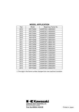
  • 1. MODEL APPLICATION Year Model Beginning Frame No. 2010 KRF750NA JKARFDN1□AB500001 2010 KRF750PA JKARFDP1□AB500001 2010 KRF750RA JKARFDR1□AB500001 2010 KRF750SA JKARFDS1□AB500001 2010 KRF750TA JKARFDT1□AB500001 2011 KRF750NB JKARFDN1□BB502601 2011 KRF750PB JKARFDP1□BB501801 2011 KRF750RB JKARFDR1□BB501001 2011 KRF750SB JKARFDS1□BB501401 2011 KRF750VB JKARFDV1□BB500001 2012 KRF750NC JKARFDN1□CB503401 2012 KRF750PC JKARFDP1□CB502901 2012 KRF750RC JKARFDR1□CB501901 2012 KRF750SC JKARFDS1□CB502801 2012 KRF750VC JKARFDV1□CB500901 2013 KRF750ND JKARFDN1□DB505201 2013 KRF750PD JKARFDP1□DB504001 2013 KRF750RD JKARFDR1□DB502601 2013 KRF750SD JKARFDS1□DB503701 □:This digit in the frame number changes from one machine to another. Part No.99924-1434-06 Printed in Japan
  • 2. TERYX 750 FI 4×4 TERYX 750 FI 4×4 LE TERYX 750 FI 4×4 SPORT Recreation Utility Vehicle Service Manual
  • 3. This quick reference guide will assist you in locating a desired topic or pro- cedure. •Bend the pages back to match the black tab of the desired chapter num- ber with the black tab on the edge at each table of contents page. •Refer to the sectional table of contents for the exact pages to locate the spe- cific topic required. Quick Reference Guide General Information 1 j Periodic Maintenance 2 j Fuel System (DFI) 3 j Cooling System 4 j Engine Top End 5 j Converter System 6 j Engine Lubrication System 7 j Engine Removal/Installation 8 j Crankshaft/Transmission 9 j Wheels/Tires 10 j Final Drive 11 j Brakes 12 j Suspension 13 j Steering 14 j Frame 15 j Electrical System 16 j Appendix 17 j
  • 4. TERYX 750 FI 4×4 TERYX 750 FI 4×4 LE TERYX 750 FI 4×4 SPORT Recreation Utility Vehicle Service Manual All rights reserved. No parts of this publication may be reproduced, stored in a retrieval system, or transmitted in any form or by any means, electronic mechanical photocopying, recording or otherwise, without the prior written permission of Quality Assurance Division/Motorcycle & Engine Company/Kawasaki Heavy Industries, Ltd., Japan. No liability can be accepted for any inaccuracies or omissions in this publication, although every possible care has been taken to make it as complete and accurate as possible. The right is reserved to make changes at any time without prior notice and without incurring an obligation to make such changes to products manufactured previously. See your dealer for the latest information on product improvements incorporated after this publication. All information contained in this publication is based on the latest product information available at the time of publication. Illustrations and photographs in this publication are intended for reference use only and may not depict actual model component parts. © 2009 Kawasaki Heavy Industries, Ltd. 6th Edition (2): Apr. 16, 2012
  • 5. LIST OF ABBREVIATIONS A ampere(s) lb pounds(s) ABDC after bottom dead center m meter(s) AC alternating current min minute(s) ATDC after top dead center N newton(s) BBDC before bottom dead center Pa pascal(s) BDC bottom dead center PS horsepower BTDC before top dead center psi pound(s) per square inch °C degree(s) Celsius r revolution DC direct current rpm revolution(s) per minute F farad(s) TDC top dead center °F degree(s) Fahrenheit TIR total indicator reading ft foot, feet V volt(s) g gram(s) W watt(s) h hour(s) Ω ohm(s) L liter(s) COUNTRY AND AREA CODES CA Canada US United States TERYX 750 FI 4×4: KRF750N/T Models TERYX 750 FI 4×4 LE: KRF750P/R/V Models TERYX 750 FI 4×4 SPORT: KRF750S Model
  • 6. EMISSION CONTROL INFORMATION To protect the environment in which we all live, Kawasaki has incorporated crankcase emis- sion (1), exhaust emission (2), and evaporative emission (3) control systems in compliance with applicable regulations of the United States Environmental Protection Agency. 1. Crankcase Emission Control System A sealed-type crankcase emission control system is used to eliminate blow-by gases. The blow-by gases are led to the breather chamber through the crankcase. Then, it is led to the air cleaner. Oil is separated from the gases while passing through the inside of the breather chamber from the crankcase, and then returned back to the bottom of crankcase. 2. Exhaust Emission Control System The exhaust emission control system applied to this engine family is engine modifications that consist of a catalytic converter in the muffler (US and CA models), a fuel injection and ignition system having optimum ignition timing characteristics. The fuel injection system has been calibrated to provide lean air/fuel mixture characteristics and opti- mum fuel economy with a suitable air cleaner and exhaust system. A maintenance free ignition system provides the most favorable ignition timing and helps maintain a thorough combustion process within the engine which contributes to a reduction of exhaust pollutants entering the atmosphere. 3. Evaporative Emission Control System The evaporative emission control system for this vehicle consists of low permeation fuel hoses and a fuel tank. The Clean Air Act, which is the Federal law covering motor vehicle pollution, contains what is commonly referred to as the Act’s "tampering provisions." "Sec. 203(a) The following acts and the causing thereof are prohibited... (3)(A) for any person to remove or render inoperative any device or element of design installed on or in a motor vehicle or motor vehicle engine in compliance with regulations under this title prior to its sale and delivery to the ultimate purchaser, or for any manufacturer or dealer knowingly to remove or render inoperative any such device or element of design after such sale and delivery to the ultimate purchaser. (3)(B) for any person engaged in the business of repairing, servicing, selling, leasing, or trading motor vehicles or motor vehicle engines, or who operates a fleet of motor vehicles know- ingly to remove or render inoperative any device or element of design installed on or in a motor vehicle or motor vehicle engine in compliance with regulations under this title follow- ing its sale and delivery to the ultimate purchaser..." NOTE ○The phrase "remove or render inoperative any device or element of design" has been generally interpreted as follows: 1. Tampering does not include the temporary removal or rendering inoperative of de- vices or elements of design in order to perform maintenance. 2. Tampering could include: a.Maladjustment of vehicle components such that the emission standards are ex- ceeded. b.Use of replacement parts or accessories which adversely affect the performance or durability of the vehicle. c.Addition of components or accessories that result in the vehicle exceeding the stan- dards.
  • 7. d.Permanently removing, disconnecting, or rendering inoperative any component or element of design of the emission control systems. WE RECOMMEND THAT ALL DEALERS OBSERVE THESE PROVISIONS OF FEDERAL LAW, THE VIOLATION OF WHICH IS PUNISHABLE BY CIVIL PENALTIES NOT EXCEEDING $10,000 PER VIOLATION.
  • 8. PLEASE DO NOT TAMPER WITH NOISE CONTROL SYSTEM (US MODEL only) To minimize the noise emissions from this product, Kawasaki has equipped it with effective intake and exhaust silencing systems. They are designed to give optimum performance while maintaining a low noise level. Please do not remove these systems, or alter them in any way which results in an increase in noise level. TAMPERING WITH EMISSION CONTROL SYSTEM PROHIBITED: Federal regulations and California State law prohibit the following acts or the causing thereof: (1) the removal or rendering inoperative by any person other than for purposes of maintenance, repair, or replacement, of any device or element of design incorporated into any new vehicle for the purposes of emission control prior to its sale or delivery to the ultimate purchaser or while it is in use, or (2) the use of the vehicle after such device or element of design has been removed or rendered inoperative by any person. Do not tamper with the original emission related parts: •Throttle body and internal parts •Spark plugs •Alternator or electronic battery ignition system •Fuel filter/Fuel injector/Fuel pump •Air cleaner element •ECU (Electronic Control Unit)
  • 9. Foreword This manual is designed primarily for use by trained mechanics in a properly equipped shop. However, it contains enough detail and basic in- formation to make it useful to the owner who de- sires to perform his own basic maintenance and repair work. A basic knowledge of mechanics, the proper use of tools, and workshop proce- dures must be understood in order to carry out maintenance and repair satisfactorily. When- ever the owner has insufficient experience or doubts his ability to do the work, all adjust- ments, maintenance, and repair should be car- ried out only by qualified mechanics. In order to perform the work efficiently and to avoid costly mistakes, read the text, thor- oughly familiarize yourself with the procedures before starting work, and then do the work care- fully in a clean area. Whenever special tools or equipment are specified, do not use makeshift tools or equipment. Precision measurements can only be made if the proper instruments are used, and the use of substitute tools may ad- versely affect safe operation. For the duration of the warranty period, we recommend that all repairs and scheduled maintenance be performed in accordance with this service manual. Any owner maintenance or repair procedure not performed in accordance with this manual may void the warranty. To get the longest life out of your vehicle: •Follow the Periodic Maintenance Chart in the Service Manual. •Be alert for problems and non-scheduled maintenance. •Use proper tools and genuine Kawasaki Vehi- cle parts. Special tools, gauges, and testers that are necessary when servicing Kawasaki vehicles are introduced by the Service Man- ual. Genuine parts provided as spare parts are listed in the Parts Catalog. •Follow the procedures in this manual care- fully. Don’t take shortcuts. •Remember to keep complete records of main- tenance and repair with dates and any new parts installed. How to Use This Manual In this manual, the product is divided into its major systems and these systems make up the manual’s chapters. The Quick Reference Guide shows you all of the product’s system and assists in locating their chapters. Each chapter in turn has its own comprehensive Ta- ble of Contents. For example, if you want engine oil informa- tion, use the Quick Reference Guide to locate the Engine lubrication System chapter. Then, use the Table of Contents on the first page of the chapter to find the Engine Oil section. Whenever you see symbols, heed their in- structions! Always follow safe operating and maintenance practices. DANGER DANGER indicates a hazardous situa- tion which, if not avoided, will result in death or serious injury. WARNING WARNING indicates a hazardous situa- tion which, if not avoided, could result in death or serious injury. NOTICE NOTICE is used to address practices not related to personal injury. This manual contains four more symbols which will help you distinguish different types of information. NOTE ○This note symbol indicates points of par- ticular interest for more efficient and con- venient operation. •Indicates a procedural step or work to be done. ○Indicates a procedural sub-step or how to do the work of the procedural step it follows. It also precedes the text of a NOTE. Indicates a conditional step or what action to take based on the results of the test or inspec- tion in the procedural step or sub-step it fol- lows. In most chapters an exploded view illustration of the system components follows the Table of Contents. In these illustrations you will find the instructions indicating which parts require spec- ified tightening torque, oil, grease or a locking agent during assembly.
  • 10. GENERAL INFORMATION 1-1 1 General Information Table of Contents Before Servicing ..................................................................................................................... 1-2 Model Identification................................................................................................................. 1-7 General Specifications............................................................................................................ 1-12 Unit Conversion Table ............................................................................................................ 1-16
  • 11. 1-2 GENERAL INFORMATION Before Servicing Before starting to perform an inspection service or carry out a disassembly and reassembly oper- ation on a vehicle, read the precautions given below. To facilitate actual operations, notes, illustra- tions, photographs, cautions, and detailed descriptions have been included in each chapter wherever necessary. This section explains the items that require particular attention during the removal and reinstallation or disassembly and reassembly of general parts. Especially note the following: Battery Ground Before completing any service on the vehicle, disconnect the battery wires from the battery to prevent the engine from accidentally turning over. Disconnect the ground wire (–) first and then the positive (+). When completed with the service, first connect the positive (+) wire to the positive (+) terminal of the battery then the negative (–) wire to the negative terminal. Edges of Parts Lift large or heavy parts wearing gloves to prevent injury from possible sharp edges on the parts. Solvent Use a high-flush point solvent when cleaning parts. High -flush point solvent should be used according to directions of the solvent manufacturer. Cleaning vehicle before disassembly Clean the vehicle thoroughly before disassembly. Dirt or other foreign materials entering into sealed areas during ve- hicle disassembly can cause excessive wear and decrease performance of the vehicle.
  • 12. GENERAL INFORMATION 1-3 Before Servicing Arrangement and Cleaning of Removed Parts Disassembled parts are easy to confuse. Arrange the parts according to the order the parts were disassembled and clean the parts in order prior to assembly. Storage of Removed Parts After all the parts including subassembly parts have been cleaned, store the parts in a clean area. Put a clean cloth or plastic sheet over the parts to protect from any foreign materials that may collect before re-assembly. Inspection Reuse of worn or damaged parts may lead to serious ac- cident. Visually inspect removed parts for corrosion, discol- oration, or other damage. Refer to the appropriate sections of this manual for service limits on individual parts. Replace the parts if any damage has been found or if the part is be- yond its service limit. Replacement Parts Replacement Parts must be KAWASAKI genuine or recommended by KAWASAKI. Gaskets, O-rings, oil seals, grease seals, circlips, cotter pins or self-locking nuts must be replaced with new ones whenever disassembled. Assembly Order In most cases assembly order is the reverse of disassem- bly, however, if assembly order is provided in this Service Manual, follow the procedures given.
  • 13. 1-4 GENERAL INFORMATION Before Servicing Tightening Sequence Generally, when installing a part with several bolts, nuts, or screws, start them all in their holes and tighten them to a snug fit. Then tighten them according to the specified se- quence to prevent case warpage or deformation which can lead to malfunction. Conversely when loosening the bolts, nuts, or screws, first loosen all of them by about a quar- ter turn and then remove them. If the specified tightening sequence is not indicated, tighten the fasteners alternating diagonally. Tightening Torque Incorrect torque applied to a bolt, nut, or screw may lead to serious damage. Tighten fasteners to the specified torque using a good quality torque wrench. Often, the tightening sequence is followed twice initial tightening and final tightening with torque wrench. Force Use common sense during disassembly and assembly, excessive force can cause expensive or hard to repair dam- age. When necessary, remove screws that have a non -permanent locking agent applied using an impact driver. Use a plastic-faced mallet whenever tapping is necessary. Gasket, O-ring Hardening, shrinkage, or damage of both gaskets and O-rings after disassembly can reduce sealing per- formance. Remove old gaskets and clean the sealing surfaces thoroughly so that no gasket material or other material remains. Install new gaskets and replace used O-rings when re-assembling. Liquid Gasket, Locking Agent For applications that require Liquid Gasket or a Non-Permanent Locking Agent, clean the surfaces so that no oil residue remains before applying liquid gasket or locking agent. Do not apply them excessively. Exces- sive application can clog oil passages and cause serious damage.
  • 14. GENERAL INFORMATION 1-5 Before Servicing Press For items such as bearings or oil seals that must be pressed into place, apply small amount of oil to the con- tact area. Be sure to maintain proper alignment and use smooth movements when installing. Ball Bearing and Needle Bearing Do not remove pressed ball or needle unless removal is absolutely necessary. Replace with new ones whenever removed. Press bearings with the manufacturer and size marks facing out. Press the bearing into place by putting pressure on the correct bearing race as shown. Pressing the incorrect race can cause pressure between the inner and outer race and result in bearing damage. Oil Seal, Grease Seal Do not remove pressed oil or grease seals unless removal is necessary. Replace with new ones whenever removed. Press new oil seals with manufacture and size marks facing out. Make sure the seal is aligned properly when installing. Apply specified grease to the lip of seal before installing the seal. Circlips, Cotter Pins Replace circlips or cotter pins that were removed with new ones. Take care not to open the clip excessively when in- stalling to prevent deformation.
  • 15. 1-6 GENERAL INFORMATION Before Servicing Lubrication It is important to lubricate rotating or sliding parts during assembly to minimize wear during initial operation. Lubri- cation points are called out throughout this manual, apply the specific oil or grease as specified. Direction of Engine Rotation When rotating the crankshaft by hand, the free play amount of rotating direction will affect the adjustment. Ro- tate the crankshaft to positive direction (clockwise viewed from right side). Electrical Wires A two-color wire is identified first by the primary color and then the stripe color. Unless instructed otherwise, electrical wires must be connected to those of the same color. Instrument Use a meter that has enough accuracy for an accurate measurement. Read the manufacture’s instructions thor- oughly before using the meter. Incorrect values may lead to improper adjustments.
  • 16. GENERAL INFORMATION 1-7 Model Identification KRF750NA, TA Left Side View KRF750NA, TA Right Side View Frame Number [A] Frame Number [B] Right Front Axle Engine Number [A] Engine Number [B] Engine Oil Drain Plug
  • 17. 1-8 GENERAL INFORMATION Model Identification KRF750NC Left Side View KRF750NC Right Side View
  • 18. GENERAL INFORMATION 1-9 Model Identification KRF750PA Left Side View KRF750PA Right Side View
  • 19. 1-10 GENERAL INFORMATION Model Identification KRF750RA, VB Left Side View KRF750RA, VB Right Side View The KRF750RA, VB are identical to the KRF750PA in every aspect: controls, features, and specifications except for the camouflage surface treatment. The gun case is an optional part.
  • 20. GENERAL INFORMATION 1-11 Model Identification KRF750SA Left Side View KRF750SA Right Side View
  • 21. 1-12 GENERAL INFORMATION General Specifications Items KRF750NA/PA/RA/SA/TA/VB ∼ ND/PD/RD/SD/VC Dimensions Overall Length 2 955 mm (116.3 in.) Overall Width 1 485 mm (58.46 in.) Overall Height : (KRF750N/S/T) 1 925 mm (75.79 in.) (KRF750P/R/V) 2 020 mm (79.53 in.) Wheelbase 1 930 mm (75.98 in.) Tread: Front 1 225 mm (48.23 in.) Rear 1 200 mm (47.24 in.) Ground Clearance 295 mm (11.6 in.) Seat Height 780 mm (30.7 in.) Curb Mass: (KRF750NA ∼ NB) 633 kg (1 396 lb), (CA) 630 kg (1 389 lb) (KRF750NC) 636 kg (1 402 lb), (CA) 633 kg (1 396 lb) (KRF750ND) 634 kg (1 398 lb), (CA) 631 kg (1 391 lb) (KRF750PA/RA ∼ PB/RB/VB) 648 kg (1 429 lb), (CA) 645 kg (1 422 lb) (KRF750PC/RC/VC) 651 kg (1 435 lb), (CA) 648 kg (1 429 lb) (KRF750PD/RD) 649 kg (1 431 lb), (CA) 646 kg (1 424 lb) (KRF750SA ∼ SB) 630 kg (1 389 lb), (CA) 627 kg (1 383 lb) (KRF750SA□A ∼ SB□A) 631 kg (1 391 lb), (CA) 628 kg (1 385 lb) (KRF750SC) 633 kg (1 396 lb), (CA) 630 kg (1 389 lb) (KRF750SD) 631 kg (1 391 lb), (CA) 628 kg (1 385 lb) (KRF750T) 634 kg (1 398 lb) Front: (KRF750NA ∼ NB) 280 kg (617 lb), (CA) 279 kg (615 lb) (KRF750NC) 281 kg (620 lb), (CA) 280 kg (617 lb) (KRF750ND) 278 kg (613 lb), (CA) 277 kg (611 lb) (KRF750PA/RA ∼ PB/RB/VB) 291 kg (642 lb), (CA) 289 kg (637 lb) (KRF750PC/RC/VC) 292 kg (644 lb), (CA) 291 kg (642 lb) (KRF750PD/RD) 289 kg (637 lb), (CA) 288 kg (635 lb) (KRF750SA ∼ SB) 279 kg (615 lb), (CA) 278 kg (613 lb) (KRF750SA□A ∼ SB□A) 280 kg (617 lb), (CA) 279 kg (615 lb) (KRF750SC) 280 kg (617 lb), (CA) 279 kg (615 lb) (KRF750SD) 277 kg (611 lb), (CA) 276 kg (609 lb) (KRF750T) 281 kg (620 lb) Rear: (KRF750NA ∼ NB) 353 kg (778 lb), (CA) 351 kg (774 lb) (KRF750NC) 355 kg (783 lb), (CA) 353 kg (778 lb) (KRF750ND) 356 kg (785 lb), (CA) 354 kg (780 lb) (KRF750PA/RA ∼ PB/RB/VB) 357 kg (787 lb), (CA) 356 kg (785 lb) (KRF750PC/RC/VC) 359 kg (792 lb), (CA) 357 kg (787 lb) (KRF750PD/RD) 360 kg (794 lb), (CA) 358 kg (789 lb) (KRF750SA ∼ SB) 351 kg (774 lb), (CA) 349 kg (770 lb)
  • 22. GENERAL INFORMATION 1-13 General Specifications Items KRF750NA/PA/RA/SA/TA/VB ∼ ND/PD/RD/SD/VC (KRF750SA□A ∼ SB□A) 351 kg (774 lb), (CA) 349 kg (770 lb) (KRF750SC) 353 kg (778 lb), (CA) 351 kg (774 lb) (KRF750SD) 354 kg (780 lb), (CA) 352 kg (776 lb) (KRF750T) 353 kg (778 lb), (CA) 351 kg (774 lb) Fuel Tank Capacity 28 L (7.4 US gal) Cargo Bed (L × W × H) 830 × 1 120 × 280 mm (32.68 × 44.09 × 11.10 in.) Seating Capacity 2 Performance Minimum Turning Radius: Differential Mode (2WD) 4.2 m (13.8 ft) Locked-Axle Mode (4WD) 5.0 m (16.4 ft) Engine Type 4-stroke, SOHC, V2-cylinders Cooling System Liquid-cooled Bore and Stroke 85.0 × 66.0 mm (3.35 × 2.60 in.) Displacement 749 cm³ (45.7 cu in.) Compression Ratio 8.8 : 1 Maximum Horsepower – Maximum Torque 57 N·m (5.8 kgf·m, 42 ft·lb) @5 000 r/min (rpm) Carburetion System Fuel Injection (Mikuni 34 × 2) Starting System Electric Starter Ignition System Battery and Coil (transistorized) Timing Advance Electronically advanced (digital) Ignition Timing 10° BTDC @1 110 r/mi (rpm) Spark Plug NGK CR7E or DENSO U22ESR-N Cylinder Numbering Method Front to rear, 1-2 Firing Order 1-2 Valve Timing: Intake: Open 20° BTDC Close 44° ABDC Duration 244° Exhaust: Open 44° BBDC Close 20° ATDC Duration 244° Lubrication System Forced lubrication (wet sump) Engine Oil: Type API SG, SH, SJ, SL or SM with JASO MA, MA1 or MA2 Viscosity SAE 10W-40 Capacity 2.6 L (2.7 US qt)
  • 23. 1-14 GENERAL INFORMATION General Specifications Items KRF750NA/PA/RA/SA/TA/VB ∼ ND/PD/RD/SD/VC Drive Train Primary Reduction System: Type Belt drive torque converter Reduction Ratio 3.200 ∼ 0.721 Transmission Gear Ratio: Forward: High 3.549 (30/26 × 29/18 × 21/11) Low 5.536 (36/20 × 29/18 × 21/11) Reverse 4.614 (16/12 × 18/16 × 29/18 × 21/11) Final Drive System: Type Shaft 4WD/2WD Reduction Ratio 4.375 (35/8) Overall Drive Ratio: Forward: High 11.195 Low 17.464 Reverse 14.553 Front Final Gear Case Oil: Type API SG, SH, SJ, SL or SM with JASO MA, MA1 or MA2 Viscosity SAE 10W-40 Capacity 0.7 L (0.74 US qt) Rear Final Gear Case Oil: Type MOBIL FLUID 424, CITGO TRANSGARD TRACTOR HYDRAULIC FLUID or EXXON HYDRAUL 560 Capacity 1.0 L (1.06 US qt) Frame Type Steel tube, Ladder Caster (Rake Angle) 2.2° Camber: (Front) -0.7° (Rear) -0.4° King Pin Angle 11.4° Trail 11 mm (0.43 in.) Tire: Front: Type Tubeless Size 26 × 8.00 - 12 Rear: Type Tubeless Size 26 × 10.00 - 12 Rim Size: Front 12 × 6.0AT Rear 12 × 8.0AT Steering Type Rack and pinion
  • 24. GENERAL INFORMATION 1-15 General Specifications Items KRF750NA/PA/RA/SA/TA/VB ∼ ND/PD/RD/SD/VC Suspension: Front: Type Double Wishbone Wheel Travel 190 mm (7.48 in.) Rear: Type Double Wishbone Wheel Travel 190 mm (7.48 in.) Brake Type: Front Disc × 2 Rear Enclosed wet multi-plate Parking Brake Type Enclosed wet multi-plate Electrical Equipment Battery (US) 12 V 14 Ah, (CA) 12 V 12 Ah Headlight: Type Semi-sealed beam Bulb 12 V 35/35 W × 2 Brake/Tail Light 12 V 27/8 W × 2 Alternator: Type Three - phase AC Max Output 28 A, 14 V @6 000 rpm Load Capacity Maximum Vehicle Load (Including Occupants and Cargo) 422 kg (931 lb) Maximum Cargo Bed Load 227 kg (500 lb) □: This blank changes depending on the model. Specifications are subject to change without notice, and may not apply to every country.
  • 25. 1-16 GENERAL INFORMATION Unit Conversion Table Prefixes for Units: Prefix Symbol Power mega M × 1 000 000 kilo k × 1 000 centi c × 0.01 milli m × 0.001 micro µ × 0.000001 Units of Mass: kg × 2.205 = lb g × 0.03527 = oz Units of Volume: L × 0.2642 = gal (US) L × 0.2200 = gal (IMP) L × 1.057 = qt (US) L × 0.8799 = qt (IMP) L × 2.113 = pint (US) L × 1.816 = pint (IMP) mL × 0.03381 = oz (US) mL × 0.02816 = oz (IMP) mL × 0.06102 = cu in Units of Force: N × 0.1020 = kg N × 0.2248 = lb kg × 9.807 = N kg × 2.205 = lb Units of Length: km × 0.6214 = mile m × 3.281 = ft mm × 0.03937 = in Units of Torque: N·m × 0.1020 = kgf·m N·m × 0.7376 = ft·lb N·m × 8.851 = in·lb kgf·m × 9.807 = N·m kgf·m × 7.233 = ft·lb kgf·m × 86.80 = in·lb Units of Pressure: kPa × 0.01020 = kgf/cm² kPa × 0.1450 = psi kPa × 0.7501 = cmHg kgf/cm² × 98.07 = kPa kgf/cm² × 14.22 = psi cmHg × 1.333 = kPa Units of Speed: km/h × 0.6214 = mph Units of Power: kW × 1.360 = PS kW × 1.341 = HP PS × 0.7355 = kW PS × 0.9863 = HP Units of Temperature:
  • 26. PERIODIC MAINTENANCE 2-1 2 Periodic Maintenance Table of Contents Periodic Maintenance Chart ................................................................................................... 2-3 Torque and Locking Agent...................................................................................................... 2-5 Specifications ......................................................................................................................... 2-13 Special Tools .......................................................................................................................... 2-15 Periodic Maintenance Procedures.......................................................................................... 2-16 Fuel System......................................................................................................................... 2-16 Throttle Pedal Free Play Inspection.................................................................................. 2-16 Throttle Pedal Free Play Adjustment ................................................................................ 2-16 Idle Speed Inspection ....................................................................................................... 2-17 Idle Speed Adjustment...................................................................................................... 2-17 Air Cleaner Element Cleaning and Inspection .................................................................. 2-17 Air Cleaner Draining.......................................................................................................... 2-18 Fuel Hose and Connections Inspection ........................................................................... 2-18 Fuel Hose Replacement ................................................................................................... 2-19 Cooling System.................................................................................................................... 2-21 Radiator Cleaning ............................................................................................................. 2-21 Water Hoses and Connections Inspection........................................................................ 2-21 Coolant Change................................................................................................................ 2-21 Engine Top End ................................................................................................................... 2-24 Valve Clearance Inspection .............................................................................................. 2-24 Valve Clearance Adjustment............................................................................................. 2-26 Spark Arrester Cleaning.................................................................................................... 2-26 Converter System................................................................................................................ 2-27 Converter Drive Belt Wear Inspection............................................................................... 2-27 Drive Belt Deflection Inspection........................................................................................ 2-29 Converter Drive Belt Deflection Adjustment...................................................................... 2-31 Actuator Lever (Engine Brake Control Lever) Assembly Inspection................................. 2-31 Engine Lubrication System.................................................................................................. 2-32 Engine Oil Change............................................................................................................ 2-32 Oil Filter Replacement ...................................................................................................... 2-33 Wheels/Tires........................................................................................................................ 2-33 Tire Inspection .................................................................................................................. 2-33 Wheels Nuts Tightness Inspection.................................................................................... 2-34 Final Drive............................................................................................................................ 2-34 Differential Shift Lever Play Inspection ............................................................................. 2-34 Differential Shift Lever Play Adjustment............................................................................ 2-34 Front Final Gear Case Oil Change ................................................................................... 2-34 Rear Final Gear Case Oil Change.................................................................................... 2-35 Brakes.................................................................................................................................. 2-36 Brake Fluid Level Inspection............................................................................................. 2-36 Brake Fluid Change .......................................................................................................... 2-37 Brake Pedal Play Inspection............................................................................................. 2-38 Brake Master Cylinder Cup and Dust Seal Replacement................................................. 2-39 Rear Brake Master Cylinder Cup, O-ring and Boot Replace ............................................ 2-40 Brake Hose and Pipe Inspection....................................................................................... 2-42 Brake Hose Replacement................................................................................................. 2-42 Parking Brake Pedal Inspection........................................................................................ 2-44 Front Brake Pad Wear Inspection..................................................................................... 2-44 Front Brake Caliper Piston Seal and Dust Seal Replacement.......................................... 2-45 Rear Brake Plates Replacement....................................................................................... 2-46
  • 27. 2-2 PERIODIC MAINTENANCE Steering ............................................................................................................................... 2-46 Steering Inspection ........................................................................................................... 2-46 Steering Joint Dust Boot Inspection.................................................................................. 2-47 Frame .................................................................................................................................. 2-47 Seat Belt Inspection.......................................................................................................... 2-47 Electrical System ................................................................................................................. 2-48 Spark Plug Cleaning/Inspection........................................................................................ 2-48 Spark Plug Gap Inspection ............................................................................................... 2-49 Brake Light Switch Inspection........................................................................................... 2-49 Brake Light Timing Adjustment ......................................................................................... 2-49 Joint Boots Inspection.......................................................................................................... 2-49 Front Axle/Steering Knuckle Joint Boots Inspection ......................................................... 2-49 Front Propeller Shaft Joint Boots Inspection..................................................................... 2-50 Tie-rod End Boots Inspection............................................................................................ 2-50 Rear Propeller Shaft Joint Boots Inspection ..................................................................... 2-50 Rear Axle/Stabilizer Joint Boots Inspection ...................................................................... 2-50 General Lubrication ............................................................................................................. 2-50 Lubrication ........................................................................................................................ 2-50 Cables.................................................................................................................................. 2-51 Inspection.......................................................................................................................... 2-51 Bolts and Nuts Tightening.................................................................................................... 2-52 Tightness Inspection ......................................................................................................... 2-52
  • 28. PERIODIC MAINTENANCE 2-3 Periodic Maintenance Chart The scheduled maintenance must be done in accordance with this chart to keep the vehicle in good running condition. The initial maintenance is vitally important and must not be neglected. FREQUENCY First Service Regular Service OPERATION After 20 h, or 200 km (120 mile) of use After 50 h, or 1 000 km (600 mile) of use Every 50 h, or 1 000 km (600 mile) of use Every 100 h, or 2 000 km (1 200 mile) of use Every 200 h, or 4 000 km (2 500 mile) of use Every year of use See Pape ENGINE Throttle pedal play-inspect • • 2-16 Fuel hoses and connections-inspect • 2-18 Fuel hose-replace 5 years 2-19 Idle speed-inspect • • 2-17 Spark plug-clean and gap inspect • • 2-48 Air cleaner-inspect * • • 2-17 Valve clearance-inspect First 2 000 km (1 200 mile); thereafter every 4 000 km (2 500 mile) 2-24 Spark arrester-clean • 2-26 Engine oil-change * • 6 months 2-32 Oil filter-replace * • • 2-33 Front and rear final gear case oil-change • • 2-34, 35 Radiator-clean * • • 2-21 Water hoses and connections-check * • 2-21 Coolant-change * 2 years 2-21 Converter drive belt wear-inspect * • 2-27 Converter drive belt deflection-inspect * • • 2-29 Differential shift lever play-inspect • • 2-34 Engine brake control lever-inspect * • 2-31 CHASSIS Rear brake plates-replace * every 10 000 km (6 000 mile) 2-46 Front brake pad wear-inspect * • • 2-44 Brake light switch - inspect • • 2-48 Brake fluid - change 2 years 2-36 Brake master cylinder cup and dust seal - replace 2 years 2-38 Rear brake master cylinder cup, O-ring, and boot-replace * 2 years 2-39 Front brake caliper piston seal and dust seal-replace 2 years 2-45 Brake hose - replace 4 years 2-42 Brake fluid level - inspect • • 2-36 Brake pedal play - inspect * • • 2-38
  • 29. 2-4 PERIODIC MAINTENANCE Periodic Maintenance Chart FREQUENCY First Service Regular Service OPERATION After 20 h, or 200 km (120 mile) of use After 50 h, or 1 000 km (600 mile) of use Every 50 h, or 1 000 km (600 mile) of use Every 100 h, or 2 000 km (1 200 mile) of use Every 200 h, or 4 000 km (2 500 mile) of use Every year of use See Pape Brake hose and pipe - inspect • • 2-41 Parking brake pedal - inspect • • 2-44 Tire wear-inspect * • • 2-33 Wheel nuts tightness - inspect • • 2-34 Joint boots - inspect • • 2-49 Steering-inspect • • 2-46 Steering joint dust boots - inspect • • 2-47 General lubrication - perform * • 2-50 Bolts, nuts, and fasteners tightness - inspect • • 2-52 Seat belt - inspect • 2-47 Cables - inspect • 2-51 *: Service more frequently when operated in mud, dust, or other harsh riding conditions, or when carrying heavy loads or pulling a trailer. •: Clean, adjust, lubricate, torque, or replace parts as necessary.
  • 30. PERIODIC MAINTENANCE 2-5 Torque and Locking Agent The following tables list the tightening torque for the major fasteners, and the parts requiring use of a non-permanent locking agent or liquid gasket. Letters used in the “Remarks” column mean: L: Apply a non-permanent locking agent. LB: Apply a non-permanent locking agent (Three Bond TB2471, Blue). LO: Apply a non-permanent locking agent (Three Bond TB2440B, Orange). Lh: Left-hand Threads MO: Apply molybdenum disulfide oil (mixture of the engine oil and molybdenum disulfide grease in a weight ratio: 10 : 1). R: Replacement Parts S: Follow the specific tightening sequence. SS: Apply silicone sealant (Liquid Gasket, TB1211: 56019-120). Torque Fastener N·m kgf·m ft·lb Remarks Fuel System Element Holder Screw 4.5 0.46 40 in·lb Element Cover Screw 4.5 0.46 40 in·lb Air Cleaner Mounting Bolts 8.8 0.90 78 in·lb L ISC Valve Mounting Bolts 8.8 0.90 78 in·lb Delivery Pipe Mounting Screws 5.0 0.51 44 in·lb Intake Air Pressure Sensor Mounting Screw 5.0 0.51 44 in·lb Throttle Cable Locknuts 4.4 0.45 39 in·lb Throttle Pedal Position Bolt Locknut 10.8 1.1 96 in·lb Fuel Pump Mounting Bolts 4.0 0.41 35 in·lb Fuel Tank Band Bolts 11 1.1 97 in·lb ECU Mounting Bolts 6.9 0.70 61 in·lb Water Temperature Sensor 12 1.2 106 in·lb Vehicle-down Sensor Bolts (KRF750ND/PD/RD/SD) 5.9 0.60 52 in·lb L Cooling System Radiator Screen Mounting Bolts 8.8 0.90 78 in·lb Radiator Cover Bracket Mounting Bolts 8.8 0.90 78 in·lb Radiator Mounting Bolts 8.8 0.90 78 in·lb Radiator Fan Assembly Bolts 8.3 0.85 73 in·lb Thermostat Housing Cover Bolts 8.8 0.90 78 in·lb Water Temperature Sensor 12 1.2 106 in·lb Water Pipe Mounting Bolts, L = 20 mm (0.79 in.) 8.8 0.90 78 in·lb Water Pipe Mounting Bolt, L = 12 mm (0.47 in.) 8.8 0.90 78 in·lb Water Pump Impeller 7.8 0.80 69 in·lb Water Pump Cover Bolts 8.8 0.90 78 in·lb Coolant Drain Plug (Water Pump) 7.0 0.71 62 in·lb Coolant Drain Plugs (Cylinder) 7.0 0.71 62 in·lb Coolant Air Bleed Bolt (Water Pump) 7.0 0.71 62 in·lb Coolant Air Bleed Bolt (Thermostat) 7.8 0.80 69 in·lb Radiator Cover Mounting Bolts (KRF750ND/PD/RD/SD) 8.8 0.90 78 in·lb
  • 31. 2-6 PERIODIC MAINTENANCE Torque and Locking Agent Torque Fastener N·m kgf·m ft·lb Remarks Engine Top End Valve Adjusting Cap Bolts 8.8 0.90 78 in·lb Rocker Case Bolts, L = 55 mm (2.2 in.) 8.8 0.90 78 in·lb S Rocker Case Bolts, L = 130 mm (5.1 in.) 9.8 1.0 87 in·lb S Rocker Case Bolts, L = 30 mm (1.2 in.) 9.8 1.0 87 in·lb S Rocker Case Bolts, L = 25 mm (1.0 in.) 9.8 1.0 87 in·lb S Cylinder Head Bolts (M10), first torque 25 2.5 18 S, MO Cylinder Head Bolts (M10), final torque 49 5.0 36 S Cylinder Head Bolts (M6) 9.8 1.0 87 in·lb Water Pipe Mounting Bolts 8.8 0.90 78 in·lb Valve Adjusting Screw Locknuts 12 1.2 106 in·lb Rocker Shaft Bolts 22 2.2 16 Rear Rocker Case Clamp Bolt 8.8 0.90 78 in·lb Camshaft Sprocket Bolts 12 1.2 106 in·lb L Chain Tensioner Cap Bolts 22 2.2 16 Chain Tensioner Mounting Bolts 8.8 0.90 78 in·lb Front Cylinder Camshaft Chain Guide Bolt 20 2.0 15 Position Plate Bolts 8.8 0.90 78 in·lb Intermediate Shaft Chain Guide Bolts 8.8 0.90 78 in·lb Intermediate Shaft Chain Tensioner Bolts 8.8 0.90 78 in·lb Rear Cylinder Camshaft Chain Guide Bolt 20 2.0 15 Cylinder Bolts, L = 30 mm (1.2 in.) 9.8 1.0 87 in·lb Cylinder Bolts, L = 40 mm (1.6 in.) 9.8 1.0 87 in·lb Coolant Drain Plugs (Cylinder) 7.0 0.71 62 in·lb Exhaust Pipe Nuts 17 1.7 13 Exhaust Pipe Cover Bolts 13 1.3 115 in·lb Muffler Clamp Bolts 15 1.5 11 Muffler Mounting Bolts 28 2.9 21 Spark Arrester Mounting Bolts 13 1.3 115 in·lb Converter System Drive Pulley Bolt 93 9.5 69 Lh Drive Pulley Cover Bolts 12.5 1.3 111 in·lb Ramp Weight Nuts 7.0 0.71 62 in·lb R Spider 275 28 203 Lh Driven Pulley Nut 93 9.5 69 R Engine Brake Actuator Mounting Bolts 8.8 0.90 78 in·lb S Engine Brake Actuator Cover Bolt 8.8 0.90 78 in·lb S Belt Inspection Opening Cover Bolts 8.8 0.90 78 in·lb Converter Cover Bolts 8.8 0.90 78 in·lb S Converter Cover Drain Bolt 20 2.0 15 Joint Duct Bolts 8.8 0.90 78 in·lb Engine Lubrication System Oil Filter 17.5 1.8 13 R
  • 32. PERIODIC MAINTENANCE 2-7 Torque and Locking Agent Torque Fastener N·m kgf·m ft·lb Remarks Oil Pressure Switch 15 1.5 11 SS Oil Pipe Bolts 8.8 0.90 78 in·lb Engine Oil Drain Plug 20 2.0 15 Oil Pressure Relief Valve 15 1.5 11 L Oil Pump Cover Bolts 8.8 0.90 78 in·lb Chain Guide Bolt 8.8 0.90 78 in·lb Oil Pump Drive Chain Tensioner Bolt 25 2.5 18 Oil Filter Mounting Bolt 25 2.5 18 L (15 mm) Plate Bolts 8.8 0.90 78 in·lb Engine Removal/Installation Engine Bracket Pipe Mounting Nuts 41.5 4.2 31 R Engine Mounting Bolt 60.1 6.1 44 Engine Mounting Nut 60.1 6.1 44 R Crankshaft/Transmission Connecting Rod Big End Cap Nuts (KRF750NA/PA/RA/SA/TA ∼ NC/PC/RC/SC/VC) 34.3 3.5 25 MO Connecting Rod Big End Cap Nuts (KRF750ND/PD/RD/SD) 36 3.7 27 MO Engine Oil Drain Plug 20 2.0 15 Crankcase Bolts (M8), L = 75 mm (2.95 in.) 20 2.0 15 S Crankcase Bolts (M8), L = 110 mm (4.33 in.) 20 2.0 15 S Crankcase Bolt (M8), L = 110 mm (4.33 in.) 20 2.0 15 S, L (1) Crankcase Bolts (M6), L = 40 mm (1.57 in.) 9.8 1.0 87 in·lb Crankcase Bolts (M6), L = 65 mm (2.56 in.) 9.8 1.0 87 in·lb Bearing Position Plate Screws 4.9 0.50 43 in·lb L Rear Cylinder Camshaft Chain Guide Bolt 20 2.0 15 Grip Hold Nut 9.8 1.0 87 in·lb Tie-rod End Locknut 19.6 2.0 14 Shift Lever Assembly Nut 19.6 2.0 14 R Tie-rod End Bolt 9.8 1.0 87 in·lb Tie-rod End Front Locknut 9.8 1.0 87 in·lb Lh Tie-rod End Rear Locknut 9.8 1.0 87 in·lb Tie-rod End Nut 19.6 2.0 14 R Shift Shaft Lever Bolt 13.5 1.4 10 Shift Shaft Cover Bolts 8.8 0.90 78 in·lb Shift Shaft Positioning Bolt 31 3.2 23 Neutral Position Switch 15 1.5 11 Reverse Position Switch 15 1.5 11 Shift Shaft Spring Bolt 25 2.5 18 LB Stopper Mounting Bolts 9.8 1.0 87 in·lb L Shift Lever Guide Bolt 8.8 0.90 78 in·lb L Shift Lever Pivot Nut 8.8 0.90 78 in·lb R Shift Lever Bracket Bolt , L = 25 mm (0.98 in.) 19.6 2.0 14 L
  • 33. 2-8 PERIODIC MAINTENANCE Torque and Locking Agent Torque Fastener N·m kgf·m ft·lb Remarks Shift Lever Bracket Bolts , L = 20 mm (0.79 in.) 19.6 2.0 14 L Front Tie-rod End 9.8 1.0 87 in·lb Stopper Spring Bolt 26 2.7 19 Wheel/Tires Front Axle Nuts 266 27.1 196 Front Wheel Nuts 110 11.2 81 S Rear Wheel Nuts 110 11.2 81 S Tie-rod End Locknuts 44 4.5 32 Rear Axle Nuts 266 27.1 196 Final Drive (Output Bevel Gears) Rotor Mounting Bolts 12 1.2 106 in·lb Output Driven Bevel Gear Housing Bolts 26 2.7 19 Bevel Gear Bearing Holder Nut 200 20.4 148 LB Bearing Holder (M64) 120 12.2 89 L Bearing Holder (M75) 250 25.5 184 L Output Shaft Holder Nut 200 20.4 148 LB Output Drive Bevel Gear Housing Bolts 26 2.7 19 Output Drive Bevel Gear Cover Bolt, L = 65 mm (2.56 in.) 8.8 0.90 78 in·lb Output Drive Bevel Gear Cover Bolts, L = 20 mm (0.79 in.) 8.8 0.90 78 in·lb Forward/Reverse Detecting Sensor Mounting Bolt 14.9 1.5 11 (Front Final Gear Case) Differential Control Shift Shaft Lever Nut 8.8 0.90 78 in·lb R Differential Shift Cable Holder Bolt 8.8 0.90 78 in·lb Front Final Gear Case Oil Filler Cap 29 3.0 21 Front Final Gear Case Oil Drain Plug 15 1.5 11 2WD/4WD Shift Cable Holder Bolts 8.8 0.90 78 in·lb L 2WD/4WD Shift Shaft Cover Bolts 8.8 0.90 78 in·lb L 2WD/4WD Shift Shaft Lever Nut 20 2.0 15 R Pinion Gear Bearing Holder Nut 200 20.4 148 LB Pinion Gear Bearing Holder 250 25.5 184 LO Coupling Nut 35 3.6 26 R Front Final Gear Case Center Cover Bolts (M8) 24 2.4 18 L Front Final Gear Case Center Cover Bolts (M10) 49 5.0 36 L Ring Gear Bolts 57 5.8 42 LB Front Final Gear Case Left Cover Bolts (M6, 35 mm) 8.8 0.90 78 in·lb Front Final Gear Case Left Cover Bolts (M6, 40 mm) 8.8 0.90 78 in·lb Front Final Gear Case Mounting Nuts 90.5 9.2 67 R Front Final Gear Case Bracket Bolts 90.5 9.2 67 Differential Shift Cable Locknuts 9.8 1.0 87 in·lb 2WD/4WD Shift Cable Locknuts 4.4 0.45 39 in·lb
  • 34. PERIODIC MAINTENANCE 2-9 Torque and Locking Agent Torque Fastener N·m kgf·m ft·lb Remarks 4WD Position Switch 15 1.5 11 Vacuum Actuator Bracket Bolts 8.8 0.90 78 in·lb Solenoid Valve Bracket Bolts 8.8 0.90 78 in·lb Vacuum Actuator Mounting Bolts 8.8 0.90 78 in·lb (Rear Final Gear Case) Rear Master Cylinder Mounting Bolts 27 2.8 20 L Rear Master Cylinder Bleed Valve 7.8 0.80 69 in·lb Rear Final Gear Case Front Cover Bolts 24 2.4 18 Spring Bracket Bolt 8.8 0.90 78 in·lb L Rear Final Gear Case Gasket Screws 1.3 0.13 12 in·lb Pinion Gear Bearing Holder 450 45.9 332 L Pinion Gear Bearing Holder Nut 200 20.4 148 LB Rear Final Gear Case Oil Drain Plug 15 1.5 11 Rear Final Gear Case Oil Filler Cap 29 3.0 21 Rear Final Gear Case Right Cover Bolts (M10) 49 5.0 36 L Rear Final Gear Case Right Cover Bolts (M12) 94 9.6 69 L Rear Final Gear Case Mounting Nuts 90.5 9.2 67 R Rear Final Gear Case Bracket Bolts 90.5 9.2 67 Heat Guard Bolts 8.8 0.90 78 in·lb Brakes Front Master Cylinder Reservoir Cap 3.4 0.35 30 in·lb Reservoir Clamp Bolt 6.2 0.63 55 in·lb Piston Stop Bolt 8.8 0.90 78 in·lb Brake Pipe Nipples 17.5 1.8 13 Brake Pipe Joint 17.5 1.8 13 Brake Hose Banjo Bolts 23.5 2.4 17 Front Master Cylinder Mounting Bolts 23.5 2.4 17 Master Cylinder Bolt 23.5 2.4 17 Push Rod Locknut 17.2 1.8 13 Parking Brake Pedal Assy Mounting Bolts 41.5 4.2 31 Front Brake Pad Mounting Bolts 17.2 1.8 13 Caliper Bleed Valves 7.8 0.80 69 in·lb Brake Hose Clamp Bolts 8.8 0.90 78 in·lb L Caliper Holder Shaft 17.2 1.8 13 Brake Caliper Mounting Bolts 33 3.4 24 L Front Brake Disc Mounting Bolts 41.5 4.2 31 L Parking Brake Position Switch Screws 0.4 0.04 4 in·lb Rear Master Cylinder Bleed Valve 7.8 0.80 69 in·lb Rear Master Cylinder Mounting Bolts 27 2.8 20 L Rear Final Gear Case Front Cover Bolts 24 2.4 18 Spring Bracket Bolt 8.8 0.90 78 in·lb L Rear Final Gear Case Gasket Screws 1.3 0.13 12 in·lb
  • 35. 2-10 PERIODIC MAINTENANCE Torque and Locking Agent Torque Fastener N·m kgf·m ft·lb Remarks Suspension Front Shock Absorber Mounting Nuts 57.5 5.9 42 R Front Suspension Arm Pivot Nuts 87.5 8.9 65 R Steering Knuckle Joint Nuts 46.5 4.7 34 Rear Shock Absorber Mounting Nuts 95.5 9.7 70 R Rear Suspension Arm Pivot Nuts 87.5 8.9 65 R Rear Knuckle Mounting Nuts 57.5 5.9 42 R Stabilizer Joint Nuts 57.5 5.9 42 R Stabilizer Holder Bolts 31.5 3.2 23 L Steering Steering Wheel Mounting Nut 54 5.5 40 R Steering Knuckle Joint Nuts 46.5 4.7 34 Main Shaft Mounting Bolts 41.5 4.2 31 Intermediate Shaft Clamp Bolts 21.5 2.2 17 Steering Gear Assembly Nuts 95.5 9.7 70 R Tie-rod End Locknuts 44 4.5 32 Tie-rod End Nuts 41.5 4.2 31 Frame Right and Left Bar Mounting Bolts 98 10 72 Upper Bar Mounting Bolts 46.5 4.7 34 Back Bar Mounting Bolts 46.5 4.7 34 Bottom Guard Bolts 8.8 0.90 78 in·lb Front Guard Bolts 31.5 3.2 23 Seat Belt Case Mounting Nuts 46.5 4.7 34 Seat Belt Mounting Bolts 41.5 4.2 31 Seat Belt Buckle Mounting Bolts 46.5 4.7 34 Seat Belt Bracket Mounting Bolts 46.5 4.7 34 Seat Plate Bolts 8.8 0.90 78 in·lb L Brake Pedal Bracket Mounting Bolts, L = 20 mm (0.79 in.) 34.3 3.5 25 L Brake Pedal Bracket Mounting Bolts, L = 30 mm (1.2 in.) 34.3 3.5 25 Center Bracket Mounting Bolts 22 2.2 16 Right Frame Pipe Mounting Bolts 34.3 3.5 25 Bracket Bolts 47 4.8 35 Heart Guard Bolts 8.8 0.90 78 in·lb Electrical System Starter Motor Mounting Bolts 8.8 0.90 78 in·lb Starter Motor Terminal Locknut 11 1.1 97 in·lb Starter Motor Cable Mounting Nut 6.8 0.69 60 in·lb Starter Motor Through Bolts 5.0 0.51 44 in·lb Starter Motor Clutch Bolts 34 3.5 25 L Left Engine Cover Bolts 5.9 0.60 52 in·lb L
  • 36. PERIODIC MAINTENANCE 2-11 Torque and Locking Agent Torque Fastener N·m kgf·m ft·lb Remarks Alternator Rotor Bolt 127 13.0 94 Alternator Cover Plugs 17.5 1.8 13 Crankshaft Sensor Mounting Bolts 5.9 0.60 52 in·lb Alternator Stator Bolts 13.5 1.4 10 Alternator Cover Bolts, L = 55 mm (2.17 in.) 8.8 0.90 78 in·lb Alternator Cover Bolts, L = 30 mm (1.18 in.) 8.8 0.90 78 in·lb Breather Plate Screws 2.9 0.30 26 in·lb L Ignition Coil Mounting Bolts 5.9 0.60 52 in·lb Spark Plugs 13 1.3 115 in·lb Vacuum Actuator Bracket Bolts 8.8 0.90 78 in·lb Solenoid Valve Bracket Bolts 8.8 0.90 78 in·lb ECU Mounting Bolts 6.9 0.70 61 in·lb Engine Brake Actuator Mounting Bolts 8.8 0.90 78 in·lb S Engine Brake Actuator Cover Bolt 8.8 0.90 78 in·lb S Forward/Reverse Detecting Sensor Mounting Bolt 14.9 1.5 11 Speed Sensor Mounting Bolt 8.8 0.90 78 in·lb Reverse Position Switch 15 1.5 11 Neutral Position Switch 15 1.5 11 4WD Position Switch 15 1.5 11 Water Temperature Sensor 12 1.2 106 in·lb Radiator Fan Assembly Bolts 8.3 0.85 73 in·lb Oil Pressure Switch 15 1.5 11 SS Battery Holder Mounting Nuts 16 1.6 12 Regulator/Rectifier Mounting Bolts 8.8 0.90 78 in·lb
  • 37. 2-12 PERIODIC MAINTENANCE Torque and Locking Agent The tables below, relating tightening torque to thread diameter, lists the basic torque for the bolts and nuts. Use this table for only the bolts and nuts which do not require a specific torque value. All of the values are for use with dry solvent-cleaned threads. Basic Torque for General Fasteners of Engine Parts TorqueThreads dia. mm (in.) Mark of bolt head N·m kgf·m ft·lb 5 (0.20) 4T 2.2 ∼ 2.6 0.22 ∼ 0.27 19 ∼ 23 in·lb 6 (0.24) 9T 12 ∼ 15 1.2 ∼ 1.5 104 ∼ 130 in·lb 6 (0.24) 7T 7.8 ∼ 9.8 0.8 ∼ 1.0 69 ∼ 87 in·lb 6 (0.24) 4T 3.9 ∼ 4.9 0.4 ∼ 0.5 35 ∼ 43 in·lb 8 (0.31) 7T 18 ∼ 22 1.8 ∼ 2.2 13 ∼ 16 8 (0.31) 4T 10 ∼ 14 1.0 ∼ 1.4 87 ∼ 122 in·lb 10 (0.39) 7T 39 ∼ 44 4.0 ∼ 4.5 29 ∼ 33 10 (0.39) 4T 20 ∼ 24 2.0 ∼ 2.4 14 ∼ 17 Basic Torque for General Fasteners of Frame Parts Torque Threads dia. mm (in.) N·m kgf·m ft·lb 5 (0.20) 3.4 ∼ 4.9 0.35 ∼ 0.50 2.5 ∼ 3.6 6 (0.24) 5.9 ∼ 7.8 0.60 ∼ 0.80 4.3 ∼ 5.8 8 (0.31) 14 ∼ 19 1.40 ∼ 1.90 10 ∼ 13 10 (0.39) 25 ∼ 34 2.60 ∼ 3.50 19 ∼ 25 12 (0.47) 44 ∼ 61 4.50 ∼ 6.20 33 ∼ 45 14 (0.55) 73 ∼ 98 7.40 ∼ 10.0 54 ∼ 72 16 (0.63) 115 ∼ 155 11.5 ∼ 16.0 83 ∼ 115 18 (0.71) 165 ∼ 225 17.0 ∼ 23.0 125 ∼ 165 20 (0.79) 225 ∼ 325 23.0 ∼ 33.0 165 ∼ 240
  • 38. PERIODIC MAINTENANCE 2-13 Specifications Item Standard Service Limit Fuel System Throttle Pedal Free Play 5 ∼ 10 mm (0.20 ∼ 0.39 in.) – – – Idle Speed 1 100 ±50 r/min (rpm) – – – Air Cleaner Element Oil High-quality foam air filter oil – – – Cooling System Coolant: Type (Recommended) Permanent type of anitfreze (soft water and ethylene glycol plus corrosion and rust inhibitor chemicals for aluminum engines and radiators) – – – Color Green – – – Mixed Ratio Soft water 50%, Coolant 50% – – – Freezing Point −35°C (−31°F) – – – Total Amount 4.4 L (4.7 US qt) – – – Engine Top End Valve Clearance: Exhaust 0.20 ∼ 0.25 mm (0.0079 ∼ 0.0098 in.) – – – Intake 0.10 ∼ 0.15 mm (0.0039 ∼ 0.0059 in.) – – – Converter System Belt Width 30.0 ∼ 30.6 mm (1.181 ∼ 1.205 in.) 28.6 mm (1.126 in.) Belt Deflection 22 ∼ 31 mm (0.87 ∼ 1.22 in.) (at checking) 22 ∼ 27 mm (0.87 ∼ 1.06 in.) (at adjusting) – – – Actuator Lever Guide Shoe Wear – – – 6 mm (0.24 in.) Engine Lubrication System Engine Oil: Type API SG, SH, SJ, SL or SM with JASO MA, MA1 or MA2 – – – Viscosity SAE 10W-40 – – – Capacity 2.4 L (2.5 US qt) (When filter is not removed) – – – 2.5 L (2.6 US qt) (When filter is removed) – – – 2.6 L (2.7 US qt) (When engine is completely dry) – – – Wheels/Tires Tire Tread Depth: Front – – – 4 mm (0.16 in.) Rear – – – 4 mm (0.16 in.) Standard tire: Front 26 × 8.00-12 – – – MAXXIS, M989, Tubeless – – – Rear 26 × 10.00-12 – – – MAXXIS, M990, Tubeless – – –
  • 39. 2-14 PERIODIC MAINTENANCE Specifications Item Standard Service Limit Final Drive Front Final Gear Case: Gear Case Oil: Type API SG, SH, SJ, SL or SM with JASO MA, MA1 or MA2 – – – Viscosity SAE 10W-40 – – – Oil Level Filler opening bottom – – – Capacity 0.7 L (0.74 US qt) – – – Rear Final Gear Case: Gear Case Oil: Type MOBIL FLUID 424, CITGO TRANSGARD TRACTOR HYDRAULIC FLUID or EXXON HYDRAUL 560 – – – Oil Level Filler opening bottom – – – Capacity 1.0 L (1.06 US qt) – – – Brakes Brake Fluid: Type DOT 3 – – – Brake Pads: Pad Lining Thickness 3.9 mm (0.15 in.) 1 mm (0.04 in.) Brake Pedal: Brake Pedal Play 2 ∼ 10 mm (0.08 ∼ 0.39 in.) – – – Steering Steering Wheel Free Play 0 ∼ 20 mm (0 ∼ 0.79 in.) – – – Electrical System Spark Plug Gap 0.7 ∼ 0.8 mm (0.028 ∼ 0.031 in.) – – – Rear Brake Light Switch Timing ON after 10 mm (0.4 in.) of pedal travel – – –
  • 40. PERIODIC MAINTENANCE 2-15 Special Tools Inside Circlip Pliers: 57001-143 Valve Adjusting Screw Holder: 57001-1217 Valve Adjuster: 57001-1232 Oil Filter Wrench: 57001-1249 Filler Cap Driver: 57001-1454 Pulley Holder Attachment: 57001-1472 Flywheel & Pulley Holder: 57001-1605 Belt Deflection Gauge: 57001-1713
  • 41. 2-16 PERIODIC MAINTENANCE Periodic Maintenance Procedures Fuel System Throttle Pedal Free Play Inspection •Check that the throttle pedal moves smoothly from full open to close. If the throttle pedal does not return properly, lubricate the throttle cable (see Throttle Cable Lubrication in the Fuel System chapter). •Check the throttle pedal play [A]. Throttle Pedal Play Standard: 5 ∼ 10 mm (0.20 ∼ 0.39 in.) If the play is incorrect, adjust the throttle cable. Throttle Pedal Free Play Adjustment •Remove: Engine Upper Cover (see Engine Upper Cover Removal in the Frame chapter) Throttle Link Case Cover •Loosen the locknut [A] and turn the adjusting nut [B] on the throttle cable until the cable has proper amount of play. •Tighten the locknut securely after adjustment. •Install: Throttle Link Case Cover Engine Upper Cover (see Engine Upper Cover Installa- tion in the Frame chapter) If the free play cannot be adjusted by using the rear cable adjusting nut, use the cable adjusting nuts [A] at front of the floorboard and make the necessary free play. ○Move the rubber seat [B]. •Start the engine. •With the transmission in neutral, operate the throttle pedal a few times to make sure that the idle speed does not change. If the idle speed does change, the throttle cable may be improperly adjusted, incorrectly routed, or it may be dam- aged. •Correct any of these conditions before operation. WARNING Operation with improperly adjusted, incorrectly routed or damaged cables could result in an unsafe riding condition. Follow the service manual to be make sure to correct any of these conditions.
  • 42. PERIODIC MAINTENANCE 2-17 Periodic Maintenance Procedures Idle Speed Inspection •Start the engine and warm it up thoroughly. •Check the idle speed with a suitable tachometer. If the idle speed is out of the specified range, check the ISC valve (see ISC Valve Inspection) and vacuum hoses. Idle Speed Standard: 1 100 ±50 r/min (rpm) Idle Speed Adjustment NOTE ○Idle speed adjustment is best performed by ECU, so idle speed cannot be adjusted. Air Cleaner Element Cleaning and Inspection NOTE ○In dusty areas, the element should be cleaned more frequently than the recommended interval. ○After riding through rain or muddy terrains, the element should be cleaned immediately. ○Also, if there is a break in the element material or any other damage to the element, replace the element with a new one. (KRF750NA/PA/RA/SA/TA ∼ NC/PC/RC/SC/VC) WARNING Gasoline and low-flash point solvents can be flammable and/or explosive and cause severe burns. Clean the element in a well-ventilated area, and take care that there is no spark or flame any- where near the working areas. Do not use gasoline or low-flash point solvents to clean the element. •Remove the air cleaner element (see Air Cleaner Element Removal in the Fuel System chapter). •Clean the element [A] in a bath of high-flash point solvent.
  • 43. 2-18 PERIODIC MAINTENANCE Periodic Maintenance Procedures •Squeeze it dry in a clean towel [A]. Do not wring the ele- ment or blow it dry; the element can be damaged. •Check all the parts of the element for visible damage. If any of the parts of the element are damaged, replace them. •After cleaning, saturate the element with a high-quality foam-air-filter oil, squeeze out the excess, then wrap it in a clean towel and squeeze it as dry as possible. ○Be careful not to tear the sponge filter. (KRF750ND/PD/RD/SD) •Remove the air cleaner element (see Air Cleaner Element Removal in the Fuel System (DFI) chapter). •Clean the paper element [A] by tapping it lightly to loosen dust. •Below away the remaining dust by applying compressed air from the inside (clean side) to outside (dirty side). •Check all the parts of the element for visible damage. If the element is damaged, replace it with a new one. Air Cleaner Draining •Remove: Engine Upper Cover (see Engine Upper Cover Removal in the Frame chapter) •Lift up the cargo bed. If any water or oil accumulates in the drain boots [A] , drain it by removing the boots. After draining, be sure to install the drain boots and clamps firmly. Fuel Hose and Connections Inspection •Remove: Engine Upper Cover (see Engine Upper Cover Removal in the Frame chapter) •Check the fuel hose. Replace the fuel hose if any fraying, leaks [A], cracks [B] or bulges [C] are noticed.
  • 44. PERIODIC MAINTENANCE 2-19 Periodic Maintenance Procedures Replace the hose if it has been sharply bent or kinked. [A] Hose Joints [B] Fuel Hose •Check that the fuel hose joints are securely connected. ○Push and pull [A] the fuel hose joint [B] back and forth more than two times, and make sure it is locked. If it does not locked, reinstall the hose joint. WARNING Leaking fuel can cause a fire or explosion resulting in serious burns. Make sure the hose joint is in- stalled correctly on the delivery pipe by sliding the joint. Fuel Hose Replacement WARNING Gasoline is extremely flammable and can be ex- plosive under certain conditions. Turn the ignition switch OFF. Do not smoke. Make sure the area is well-ventilated and free from any source of flame or sparks; this includes any appliance with a pilot light. •Be sure to place a piece of cloth around the fuel hose joint. •Wipe off the dirt of the surface [A] around the connection using a cloth or a soft brush.
  • 45. 2-20 PERIODIC MAINTENANCE Periodic Maintenance Procedures When removing with standard tip screwdriver •Insert the standard tip screwdriver [A] into the slit on the joint lock [B]. •Turn the driver to disconnect the joint lock. When removing with fingers •Open and push up [C] the joint lock with your fingers. NOTICE Prying or excessively widening the joint lock ends for fuel hose removal will permanently deform the joint lock, resulting in a loose or incomplete lock that may allow fuel to leak and create the potential for a fire explosion. To prevent fire or explosion from a damaged joint lock, do not pry or excessively widen the joint lock ends when removing the fuel hose. The joint lock has a retaining edge that locks around the housing. •Pull the fuel hose out of the pipe. •Cover the delivery pipe with the vinyl bag to keep it clean. •Remove the vinyl bag on the pipe. •Check that there are no flaws, burrs, and adhesion of foreign materials on the delivery pipe [A]. •Replace the fuel hose with a new one. •Apply engine oil to the pipe. •Insert the fuel hose joint [A] securely onto the pipe [B] and push down the joint lock [C]. •Push and pull the fuel hose joint back and forth [A] more than two times and make sure it is locked and doesn’t come off. WARNING Leaking fuel can cause a fire or explosion resulting in severe burns. Make sure the fuel hose joint is installed correctly on the delivery pipe and that it doesn’t leak. If it comes off, reinstall the hose joint. •Start the engine and check the fuel hose for leaks.
  • 46. PERIODIC MAINTENANCE 2-21 Periodic Maintenance Procedures Cooling System Radiator Cleaning NOTICE Clean the radiator screen and the radiator in ac- cordance with the Periodic Maintenance Chart. In dusty areas, they should be cleaned more fre- quently than the recommended interval. After riding through muddy terrains, the radiator screen and the radiator should be cleaned immediately. •Remove the front fender front (see Front Fender Front Removal in the Frame chapter). •Remove: Radiator Cover (see Radiator Removal in the Cooling chapter) Radiator Screen Mounting Screws [A] (bothside) Radiator Screen [B] •Clean the radiator screen in a bath of tap water, and then dry it with compressed air or by shaking it. •Clean the radiator. NOTICE When cleaning the radiator with steam cleaner, be careful of the following to prevent radiator damage. Keep the steam gun [A] away more than 0.5 m (20 in.) [B] from the radiator core. Hold the steam gun perpendicular [C] (not oblique [D]) to the core surface. Run the steam gun following the core fin direction. Water Hoses and Connections Inspection ○The high pressure inside the water hose can cause coolant to leak [A] or the hose to burst if the line is not properly maintained. Visually inspect the hoses for signs of deterioration. Squeeze the hoses. A hose should not be hard and brittle, nor should it be soft or swollen. Replace the hose if any fraying, cracks [B] or bulges [C] are noticed. •Check that the hoses are securely connected and clamps are tightened correctly. Coolant Change WARNING Coolant can be extremely hot and cause severe burns, is toxic and very slippery. Do not remove the radiator cap or attempt to change the coolant when the engine is hot; allow it cool completely. Immediately wipe any spilled coolant from tires, frame, engine or other painted parts. Do not ingest coolant.
  • 47. 2-22 PERIODIC MAINTENANCE Periodic Maintenance Procedures •Tilt up and hold the front fender front (see Front Fender Front Removal in the Frame chapter). •Remove: Engine Upper Cover (see Engine Upper Cover Removal in the Frame chapter) Seat Lower Cover (see Seat Lower Cover Removal in the Frame chapter) Left Cover (see Left Cover Removal in the Frame chap- ter) Engine Bottom Guard (see Engine Bottom Guard Re- moval in the Frame chapter) •Place a container and a suitable paper [A] or plate under the drain plug [B] at the bottom of the water pump cover [C], and then remove the drain plug. •Remove the radiator cap [A] in two steps. First, turn the cap counterclockwise to the first step. Then push and turn it further in the same direction and remove the cap. •The coolant will drain from the radiator and engine. •Remove: Torque Converter Intake Duct •Place a container under the drain plug [A] at the front cylinder, then remove the drain plug. •Place a container under the drain plug [A] at the rear cylin- der, then remove the drain plug.
  • 48. PERIODIC MAINTENANCE 2-23 Periodic Maintenance Procedures •Remove: Overflow Hose [A] and Clamp Screw [B] •Remove the reserve tank cap [C], and pour the coolant into a container. •Install the water hoses to the water pipes and tighten the clamp screw. •Install: Overflow Hose and Clamp Reserve Tank [A] ○Insert the projection [B] into the grommet [C]. •Tighten the screws. •Fill the radiator up to the radiator filler neck [A] with coolant. NOTE ○Pour in the coolant slowly so that the air in the engine and radiator can escape. •Fill the reserve tank up to the F (Full) level line with coolant. NOTE ○Pour in the coolant slowly so that the air in the engine and radiator can escape. NOTICE Soft or distilled water must be used with the an- tifreeze in the cooling system. If hard water is used in the system, it causes scale accumulation in the water passages, considerably reducing the efficiency of the cooling system. Water and Coolant Mixture Ratio (when shipping) Soft Water: 50% Coolant: 50% Freezing Point: −35°C (−31°F) Total Amount: 4.4 L (4.7 US qt) NOTE ○Choose a suitable mixture ratio by referring to the coolant manufacturer’s directions.
  • 49. 2-24 PERIODIC MAINTENANCE Periodic Maintenance Procedures •Bleed the air from the cooling system as follows. ○Start the engine with the radiator cap removed and run it until no more air bubbles [A] can be seen in the coolant. ○Tap the radiator hoses to force any air bubbles caught inside. ○Stop the engine and add coolant up to the radiator filler neck. •Install the radiator cap. •Start the engine, warm it up thoroughly until the radiator fan turns on and then stop the engine. •Check the coolant level in the reserve tank after the en- gine cools down. If the coolant level is lower than the L (Low) level line [A], add coolant to the F (Full) level line [B]. NOTICE Do not add more coolant above the full level line. •Install the reserve tank cap. Engine Top End Valve Clearance Inspection NOTE ○Check the valve clearance only when the engine is cold (at room temperature). •Remove: Seat Lower Cover (see Seat Lower Cover Removal in the Frame chapter) Air Cleaner Housing and Duct (see Air Cleaner Housing and Duct Removal in the Fuel System (DFI) chapter) Air Outer Duct (see Torque Converter Cover Removal in the Converter System chapter) Center Bracket (see Center Bracket Removal in the Frame chapter) Valve Adjusting Caps [A] •Remove (KRF750NA/PA/RA/SA/TA ∼ NC/PC/RC/SC/VC): Left Cover (see Left Cover Removal in the Frame chap- ter) Bolts [A] and Engine Left Cover [B]
  • 50. PERIODIC MAINTENANCE 2-25 Periodic Maintenance Procedures •Remove (KRF750ND/PD/RD/SD): Alternator Cover Center Cap [A] Special Tool - Filler Cap Driver: 57001-1454 •Remove the timing inspection plug [A]. Special Tool - Filler Cap Driver [B]: 57001-1454 •Turn the crankshaft counterclockwise with a wrench on the alternator rotor bolt until “T-R” mark [A] on the alter- nator rotor aligns with the notch [B] as shown: the end of the compression stroke in the rear cylinder head. •Measure the clearance for all four valves, one at a time between the end of the valve stem and the adjusting screw [A] with the thickness gauge [B]. Valve Clearance (when cold) Exhaust 0.20 ∼ 0.25 mm (0.0079 ∼ 0.0098 in.) Intake 0.10 ∼ 0.15 mm (0.0039 ∼ 0.0059 in.) If the valve clearance is not correct, adjust it (see Valve Clearance Adjustment). •Then, turn the crankshaft counterclockwise with a wrench on the alternator rotor bolt until “T-F” mark [A] on the alternator rotor aligns with the notch [B] as shown: the end of the compression stroke in the front cylinder head. •Measure the clearance for all four valves, one at a time between the end of the valve stem and the adjusting screw with the thickness gauge. Valve Clearance (when cold) Exhaust 0.20 ∼ 0.25 mm (0.0079 ∼ 0.0098 in.) Intake 0.10 ∼ 0.15 mm (0.0039 ∼ 0.0059 in.) If the valve clearance is not correct, adjust it (see Valve Clearance Adjustment).
  • 51. 2-26 PERIODIC MAINTENANCE Periodic Maintenance Procedures Valve Clearance Adjustment •Remove the valve adjusting caps. •Loosen the locknut and turn the adjusting screw until the clearance is correct. •For the KRF750NA/PA/RA/SA/TA ∼ NB/PB/RB/SB/VB early models, using the valve adjuster [A], hold the ad- justing screw from turning and tighten the locknut. Special Tool - Valve Adjuster: 57001-1232 Torque - Valve Adjusting Screw Locknuts: 12 N·m (1.2 kgf·m, 106 in·lb) •For the KRF750NC/PC/RC/SC/VC ∼ models, holding the adjusting screw with the holder, tighten the locknut. Special Tool - Valve Adjusting Screw Holder: 57001-1217 Torque - Valve Adjusting Screw Locknuts: 12 N·m (1.2 kgf·m, 106 in·lb) •Recheck the clearance. If the clearance is incorrect, repeat the adjustment proce- dure. If the clearance is correct, perform the adjustment proce- dure on the other valve. Spark Arrester Cleaning WARNING The muffler can become extremely hot during nor- mal operation and cause severe burns. Since the engine must be running during this procedure, wear heat-resistant gloves while cleaning the spark ar- rester. •Remove: Bolts [A] Spark Arrester [B] •Clean the spark arrester [A] in a bath of high-flash point solvent and if necessary use a fine wire brush to gently remove any particles in the screen.
  • 52. PERIODIC MAINTENANCE 2-27 Periodic Maintenance Procedures •In an open area away from combustible materials, start the engine with the transmission in neutral. •Raise and lower engine speed while tapping on the muf- fler with a rubber mallet until carbon particles are purged from the muffler. DANGER Exhaust gas contains carbon monoxide, a color- less, odorless poisonous gas. Inhaling carbon monoxide can cause serious brain injury or death. DO NOT run the engine in enclosed areas. Operate only in a well-ventilated area. •Stop the engine. •Apply grease to the new gasket [A] and install it on the muffler. •Install the spark arrester [B] so that the opening [C] of the pipe faces downward. •Tighten: Torque - Spark Arrester Mounting Bolts: 13 N·m (1.3 kgf·m, 115 in·lb) Converter System Converter Drive Belt Wear Inspection Inspection of the drive belt is required at least every 200 hours, 6 months of vehicle use or 4 000 km (2 500 mi.) whichever comes first. An average day of use is calculated as 20 km (13 mi.) per day or 1.1 hours. More frequent inspection is necessary if the vehicle is subjected to hard usage. WARNING Neglect, abuse, or failure to maintain the transmis- sion can result in a severely worn or damaged drive belt locking up the transmission and wheels. This can cause the operator to lose control and have an accident resulting in injury or death. Maintain ac- cording to periodic maintenance chart. •Remove: Engine Upper Cover (see Engine Upper Cover Removal in the Frame chapter) Bands [A] (cut) Air Outlet Duct [B]
  • 53. 2-28 PERIODIC MAINTENANCE Periodic Maintenance Procedures •Check the belt [A] for breaks. If necessary, replace the belt. •Push the drive belt [A] between the driven sheaves and check the belt position in the driven sheaves. If the upper surface [B] of the drive belt is lowered 1.5 mm (0.059 in.) [C] or more from the edge [D] of sheaves, check the belt wear as follows. •Remove the torque converter cover (see Torque Con- verter Cover Removal in the Converter System chapter). •Measure the width [A] of the belt at several locations with a pair of suitable straightedges [B] as shown. If any measurements exceed the service limit, replace the belt. Belt Width Standard: 30.0 ∼ 30.6 mm (1.181 ∼ 1.205 in.) Service Limit: 28.6 mm (1.126 in.) •Check the belt [A] for abnormal wear [B]. ○Measure the width [C] of the belt at abnormal wear point. If any measurements exceed 0.5 mm (0.02 in.), replace the belt. •Check the belt for cracks, breaks, or peeling. If necessary, replace the belt. Belt [A] Crack [B] Broken [C] Peeling [D]
  • 54. PERIODIC MAINTENANCE 2-29 Periodic Maintenance Procedures NOTE ○Whenever the belt is replaced, inspect the drive and the driven pulleys. •Install the air outlet duct (see Torque Converter Cover In- stallation in the Converter System chapter). Drive Belt Deflection Inspection •Put the transmission in neutral and rotate the driven pulley by hand to make sure the belt is shifted all the way to the top of the driven pulley. •Remove: Engine Upper Cover (see Engine Upper Cover Removal in the Frame chapter) Bolts [A] Clamp [B] Cover [C] •Set the cover plate [A] on the torque converter cover [B] with two bolts [C]. Special Tool - Belt Deflection Gauge: 57001-1713 •Put the belt deflection gauge [A] along with the semi-circle cutout [B] in the cover plate and let the flat end of the gauge contact at right angle to the belt [C]. NOTE ○Take care not to drop the gauge in the converter cover. •Press [A] the gauge head until the 59 N (6 kgf, 13 lb) scale line [B] aligns with the top end of the stopper [C]. •Make a line mark [D] on the gauge at the upper surface of the cover plate [E].
  • 55. 2-30 PERIODIC MAINTENANCE Periodic Maintenance Procedures •Remove the gauge and measure the distance [L] between the mark [D] and the gauge bottom end. •Calculate the belt deflection [H]. H = L (mm) – 82.4 (mm) or H = L (in.) – 3.24 (in.) Belt Deflection Belt Deflection Standard: 22 ∼ 31 mm (0.87 ∼ 1.22 in.) (at checking) (For reference) The 82.4 mm (3.24 in.) is the distance be- tween the top surface of cover plate and the design base point of the drive belt for measuring. If the belt deflection is not within the specified range, ad- just the deflection by adding or removing spacers on the fixed sheave of the driven pulley. NOTE ○This is timesaving preliminary drive belt deflection mea- suring method. When recheck the belt deflection after deflection adjustment, follow the standard method de- scribed below. ○If the belt deflection is not within the standard, adjust it by adding or removing spacers on the fixed sheave of the driven pulley. NOTE ○For easy drive belt deflection judgment, put a 9 mm wide tape [A] at the position on the belt deflection gauge as shown in the figure. With this tool the technician can judge the deflection directly by checking the position of the tape against the cover plate. Standard Drive Belt Deflection Measurement •After deflection adjustment, check the belt deflection be- fore installing the CVT cover following the method de- scribed below. •Measure the belt deflection [A] at the middle of two pulleys with a straightedge, the belt deflection gauge and a ruler. •Place a straightedge [B] on top of the belt between the drive pulley [C] and the driven pulley [D]. •Push the belt away from the straightedge with the belt deflection gauge. Press the gauge head until the 59 N scale line aligns with the top end of the stopper. Belt Deflection Standard: 22 ∼ 27 mm (0.87 ∼ 1.06 in.) (at adjusting) If the belt deflection is not within the specified range, ad- just the deflection again.
  • 56. PERIODIC MAINTENANCE 2-31 Periodic Maintenance Procedures Converter Drive Belt Deflection Adjustment •Disassemble the driven pulley (see Driven Pulley Disas- sembly in the Converter System chapter). If the belt deflection is more than 31 mm (1.22 in.), remove the spacers to decrease it. ○The rule-of-thumb is: 0.1 mm (0.004 in.) change in spacer thickness equals about 1.3 mm (0.051 in.) change in belt deflection. If the adjustment cannot be done within the specified range even if the shim is removed, replace the drive belt. If the belt deflection is less than 22 mm (0.87 in.), add the spacers [A] to increase it. ○The rule-of-thumb is: 0.1 mm (0.004 in.) change in spacer thickness equals about 1.6 mm (0.063 in.) change in belt deflection. NOTE ○When using the plural spacers, install the thick spacer to the movable sheave side and thin spacer to the fixed sheave side. Spacers Part No. Thickness 92026-0034 0.3 mm (0.012 in.) 92026-1569 0.6 mm (0.024 in.) 92026-1617 0.8 mm (0.031 in.) 92026-1565 1.0 mm (0.039 in.) 92026-1570 1.4 mm (0.055 in.) •Assemble the driven pulley (see Driven Pulley Assembly in the Converter System chapter). •With the transmission in neutral, rotate the driven pulley to allow the belt to return to the top of the sheaves before measuring the belt deflection. •Measure the belt deflection again and repeat the above procedures until it is within the standard range. •Using the flywheel & pulley holder and pulley holder at- tachment, tighten the new driven pulley nut. Special Tools - Flywheel & Pulley Holder: 57001-1605 Pulley Holder Attachment: 57001-1472 Torque - Driven Pulley Nut: 93 N·m (9.5 kgf·m, 69 ft·lb) Actuator Lever (Engine Brake Control Lever) Assembly Inspection •Remove the torque converter cover (see Torque Con- verter Cover Removal in the Converter System chapter). •Measure the width [A] of the plastic guide shoe [B] of the actuator lever assembly. If the guide contact area width is greater than the service limit, replace the actuator lever assembly. Actuator Lever Guide Shoe Service Limit: 6 mm (0.24 in.)
  • 57. 2-32 PERIODIC MAINTENANCE Periodic Maintenance Procedures Engine Lubrication System Engine Oil Change •Remove: Bottom Guard Bolts [A] Bottom Guard [B] •Support the vehicle so that it is level, both side to side and front to rear after warming up the engine. •Remove the engine oil drain plug [A] to drain the oil. ○The oil in the filter can be drained by removing the filter (see Oil Filter Change). •Replace the oil drain plug gasket with a new one. •Tighten: Torque - Engine Oil Drain Plug: 20 N·m (2.0 kgf·m, 15 ft·lb) •Pour in the specified type and amount of oil. Engine Oil Type: API SG, SH, SJ, SL or SM with JASO MA, MA1 or MA2 Viscosity: SAE 10W-40 Amount: 2.4 L (2.5 US qt) (When filter is not removed) 2.5 L (2.6 US qt) (When filter is removed) 2.6 L (2.7 US qt) (When engine is completely dry) NOTE ○Although 10W-40 engine oil is the recommended oil for most conditions, the oil viscosity may need to be changed to accommodate atmospheric conditions in your riding area. •Install: Bottom Guard (see Engine Bottom Guard Installation in the Frame chapter)
  • 58. PERIODIC MAINTENANCE 2-33 Periodic Maintenance Procedures Oil Filter Replacement •Remove: Engine Bottom Guard (see Engine Bottom Guard Re- moval in the Frame chapter) •Drain the engine oil. •Remove the oil filter [A] with the oil filter wrench [B]. Special Tool - Oil Filter Wrench: 57001-1249 •Replace the filter with a new one. •When installing the oil filter, be careful of the following. ○Apply oil to the gasket [A] before installation. ○Tighten the filter with the oil filter wrench. Special Tool - Oil Filter Wrench: 57001-1249 Torque - Oil Filter: 17.5 N·m (1.8 kgf·m, 13 ft·lb) ○Pour in the specified type and amount of oil. •Install: Engine Bottom Guard (see Engine Bottom Guard Instal- lation in the Frame chapter) Wheels/Tires Tire Inspection •Examine the tire for damage and wear. If the tire is cut or cracked, replace it. ○Lumps or high spots on the tread or sidewalls indicate internal damage requiring tire replacement. ○Remove any foreign objects from the tread. After re- moval, check for leaks with a soap and water solution. •Measure the tread depth at the center of the tread with a depth gauge [A]. Since the tire may wear unevenly, take measurements at several places. If any measurements are less than the service limit, re- place the tire. Tire Tread Depth Service Limit: Front 4 mm (0.16 in.) Rear 4 mm (0.16 in.) Standard Tire Front: 26 × 8.00 - 12 MAXXIS, M989, Tubeless Rear: 26 × 10.00 - 12 MAXXIS, M990, Tubeless
  • 59. 2-34 PERIODIC MAINTENANCE Periodic Maintenance Procedures Wheels Nuts Tightness Inspection •Check the tightness of all the wheel nuts. If there are loose nut, first loosen by 1/2 turn, then re- torque them to the specified torque. Torque - Wheel Nuts: 110 N·m (11.2 kgf·m, 81 ft·lb) ○Tighten the wheel nuts [1] ∼ [4] in a criss-cross pattern. Final Drive Differential Shift Lever Play Inspection •Check the differential shift lever travel by feeling clicks. •Push the center [A] of the damper [B] with 98 N (10 kgf, 22 lbf) of force. ○The differential shift lever travel should be about 5 notches (clicks). Differential Shift Lever Travel Standard: about 5 notches (clicks) at 98 N (10 kgf, 22 lbf) If the lever travel is more than 9 notches (clicks) at 98 N (10 kgf, 22 lbf), adjust the cable. Differential Shift Lever Play Adjustment •Loosen the differential shift cable locknuts [A] at the front final gear case. •Turn the nuts to obtain the correct amount of travel. •Tighten: Torque - Differential Shift Cable Locknuts: 9.8 N·m (1.0 kgf·m, 87 in·lb) Front Final Gear Case Oil Change •Warm up the oil by running the vehicle so that the oil will pick up any sediment and drain easily. Then stop the vehicle. •Park the vehicle so that it is level, both side-to-side and front-to-rear. •Place an oil pan beneath the front final gear case and remove the oil drain plug [A]. WARNING Oil on tires can cause loss of traction and an ac- cident resulting in serious injury or death. When draining or filling the final gear case, do not spill oil the tire or rim. Clean any oil that may spill with a high-flash point solvent. •After the oil has completely drained out, install the oil drain plug with a new O-ring. ○Apply grease to the O-ring. •Tighten: Torque - Front Final Gear Case Oil Drain Plug: 15 N·m (1.5 kgf·m, 11 ft·lb)
  • 60. Thank you very much for your reading. Please Click Here Then Get More Information.