Download to read offline
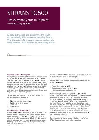


Recognizing temperature profiles and detailed understand- ing of the process are great challenges to plant operators. The fiber-optic based SITRANS TO500 multipoint measuring system enables you to determine a large number of tem- perature measuring points along a single sensor fiber and read out a temperature profile in a matter of seconds. For example, you can quickly and precisely identify points overheating to help avoid or counteract potential damage to your product and/or equipment.


