A Beginners Guide to Building a RAG App Using Open Source Milvus
Foam Rocket Assignment
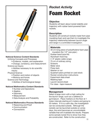
1. Rocket Activity
Foam Rocket
Objective
Students will learn about rocket stability and
trajectory with rubber band-powered foam
rockets.
Description
Students will construct rockets made from pipe
insulating foam and use them to investigate the
trajectory relationship between launch angle
and range in a controlled investigation.
Materials
30 cm-long piece of polyethylene foam pipe
insulation (for 1/2” size pipe )
Rubber band (size 64)
National Science Content Standards Styrofoam food tray
Unifying Concepts and Processes 3 8” plastic cable wraps
• Evidence, models, and explanation 75 cm of ordinary string
• Change, constancy, and measurement Scissors
Science as Inquiry Meter stick
• Abilities necessary to do scientific Press tack
inquiry Washer or nut
Physical Science Quadrant plans printed on card stock
• Position and motion of objects Rocket construction instructions
• Motions and forces Experiment data sheet
Science and Technology Masking tape
• Abilities of technological design Launch record sheet
For class - tape measure
National Mathematics Content Standards
• Number and Operations
• Algebra Management
• Geometry Select a large room with a high ceiling for
• Measurement the launch range, such as a cafeteria or
• Data Analysis and Probability gymnasium. Place markers on the floor at 1
meter intervals starting at 5 meters and going to
National Mathematics Process Standards 20 meters. If it is a calm day, the investigation
• Reasoning and Proof can be conducted outside. Although the
• Communication rockets can be launched outside on windy
• Connections days, the wind becomes an uncontrollable
variable that will invalidate the results. Prepare
some sample rocket fins to show how they
are constructed. Refer to the construction
72
2. page for details. Before conducting the
investigation, review the concept of control.
Tip Be sure the range-measuring student
In this investigation, control will be how much measures where the rocket touches down and
the rubber band is stretched when launching not where the rocket ends up after sliding or
the rockets. The experimental variable will be bouncing along the floor.
the angle of launch. Students will compare
the launch angle with the distance the rocket
travels. Organize students into teams of three. In flight, foam rockets are stabilized by
One student is the launcher. The second their fins. The fins, like feathers on an arrow,
student confirms the launch angle and gives the keep the rocket pointed in the desired direction.
launch command. The third student measures If launched straight up, the foam rocket will
the launch distance, records it, and returns point upward until it reaches the top of its flight.
the rocket to the launch site for the next flight. Both gravity and air drag put act as brakes. At
The experiment is repeated twice more with the very top of the flight, the rocket momentarily
students switching roles. The distances flown becomes unstable. It flops over as air catches
will be averaged, and students will predict what the fins and becomes stable again when it falls
the best launch angle should be to obtain the back nose forward.
greatest distance from the launch site. When the foam rocket is launched at
an angle of less than 90 degrees, it generally
Background remains stable through the entire flight. Its path
The foam rocket flies ballistically. It receives is an arc whose shape is determined by the
its entire thrust from the force produced by launch angle. For high launch angles, the arc is
the elastic rubber band. The rubber band is steep, and for low angles, it is broad.
stretched. When the rocket is released, the When launching a ballistic rocket straight
rubber band quickly returns to its original up (neglecting air currents) the rocket will fall
length, launching the foam rocket in the straight back to its launch site when its upward
process. Technically, the foam rocket is a motion stops. If the rocket is launched at an
rocket in appearance only. The thrust of real angle of less than 90 degrees, it will land at
rockets typically continues for several seconds some distance from the launch site. How far
or minutes, causing continuous acceleration, away from the launch site is dependent on four
until propellants are exhausted. The foam things. These are:
rocket gets a quick pull and thrusting is over.
Once in flight, it coasts. Furthermore, the mass gravity
of the foam rocket doesn’t change in flight. launch angle
Real rockets consume propellants and their initial velocity
total mass diminishes. Nevertheless, the flight atmospheric drag
of a foam rocket is similar to that of real rockets. Gravity causes the foam rocket to decelerate
Its motion and course is affected by gravity and as it climbs upward and then causes it to
by drag or friction with the atmosphere. The accelerate as it falls back to the ground. The
ability to fly foam rockets repeatedly (without launch angle works with gravity to shape the
refueling) makes them ideal for classroom flight path. Initial velocity and drag affects the
investigations on rocket motion. flight time.
The launch of a foam rocket is a good In the investigation, students will
demonstration of Newton’s third law of motion. compare the launch angle to the range or
The contraction of the rubber band produces distance the foam rocket lands from the
an action force that propels the rocket forward launch site. Launch angle is the independent
while exerting an opposite and equal force on variable. Gravity can be ignored because the
the launcher. In this activity, the launcher is a acceleration of gravity will remain the same for
meter stick held by the student. all flight tests.
73
3. Atmospheric drag can be ignored o
75
because the same rocket will be
flown repeatedly. Although o
60
students will not know the initial
velocity, they will control for it by
o
stretching the rubber band the 45
same amount for each flight. The
dependent variable in the 30
o
experiment is the distance the
rocket travels. o
o
Assuming student teams 15
15
are careful in their control
of launch angles and in the
Launch angle vs. range for rockets with the same initial launch velocity
stretching of the launch band,
they will observe that their
farthest flights will come from launches with Join the cable wrap to form a loop and
an angle of 45 degrees. They will also observe tighten it down to a circle approximately 1 to
that launches of 30 degrees, for example, will 2 cm in diameter. The end of the wrap can be
produce the same range as launches of 60 trimmed off with scissors or left.
degrees. Twenty degrees will produce the 5. Thread the cable wrap with string and rubber
same result as 70 degrees, etc. (Note: Range launch band through the hole in the foam
distances will not be exact because of slight tube. The string should stick out the rear end
differences in launching even when teams of the rocket and the rubber band out the
are very careful to be consistent. However, nose. Position the plastic loop about 3 cm
repeated launches can be averaged so that the back from the nose.
ranges more closely agree with the illustration. 6. Tighten the second cable wrap securely
around the nose of the rocket. It should be
Procedures Constructing a Foam Rocket positioned so that the cable wrap loop inside
1. Using scissors, cut one 30-cm length of pipe the rocket is unable to be pulled out the nose
foam for each team. when the rubber band is stretched. Caution
2. Cut four equally spaced slits at one end of students not to pull on the string. The
the tube. The slits should be about 8 to 10 string should only be pulled during launches
cm long. The fins will be mounted through when the rubber band is held from the other
these slits. end. Trim off the excess cable wrap end.
3. Tie a string loop that is about 30 cm long. 7. Cut fin pairs from the foam food tray or stiff
4. Slip one end of a cable wrap through the cardboard. Refer to the fin diagram.
string loop and through the rubber launch band.
Launch string loop Plastic cable wrap
Launch rubber band
Plastic cable wrap Internal plastic
cable wrap
74
4. Both fin pairs should be notched so that they
can be slid together as shown in the diagram.
Different fin shapes can be used, but they
should still “nest” together.
8. Slide the nested fins into the slits cut in the
rear end of the rocket. Make sure the string
Cut slots the same width as the
thickness of the fin stock.
loop hangs out the “engine” end.
9. Tighten the third cable wrap around the rear
of the rocket. This will hold the fins in place.
Trim off the excess cable wrap end.
Procedure Making the Launcher
1. Print the quadrant pattern (page 78) on card
stock paper.
Nest fins together.
2. Cut out the pattern and fold it on the dashed
line.
3. Tape the quadrant to the meter stick so that
the black dot lies directly over the 60 cm
mark on the stick.
4. Press a push tack into the black dot.
Different fin shapes can be used.
10
20
30
40
50
90
0
80
10
70 20
60 30
50 40
80
Launcher ready for a 45-degree angle launch.
90
75
5. 5. Tie a string to the push tack and hand a small Students will have to determine initial velocity.
weight, such as a nut or a washer on the If available, photogate equipment can be
string. The weight should swing freely. used for determining the initial velocity.
6. Refer to the diagram to see how the launcher Otherwise, challenge students to derive an
is used. method for estimating initial velocity. One
approach might be to launch the rocket
Discussion: horizontally from a table top and measure the
• Why didn’t the experiment protocol call for horizontal distance the rocket travels as it falls
launching at 0 and 90 degrees? to the floor. Using a stopwatch, measure the
Assuming a perfect launch, a rocket launched time the rocket takes to reach the floor. If the
straight upwards should return exactly to rocket takes 0.25 seconds to reach the floor
the launch pad. Any variation in the impact and traveled 3 meters horizontally while doing
site will be due to air currents and not to the so, multiply 3 meters by 4. The initial velocity
launch angle. A rocket launched horizontally will be 12 meters per second. Students
will travel only as far as the time it takes to should repeat the measurement several
drop to the floor. times and average the data to improve their
• Shouldn’t the rocket be launched from the accuracy. (This method assumes no slowing
floor for the experiment? of the rocket in flight due to air drag.)
Yes. However, it is awkward to do so. • Different kinds of fins can be constructed for
Furthermore, student teams will be measuring the foam rocket. Try creating a space shuttle
the total distance the rocket travels and orbiter or a future rocket plane for exploring
consistently launching from above the floor the atmosphere of other planets.
will not affect the outcome.
Assessment:
• Have student teams submit their completed
data sheets with conclusions.
• Have students write about potential practical
uses for the foam rocket (e.g. delivering
messages).
Extensions:
• For advanced students, the following
equation can be used for estimating ranges.
(g is the acceleration of gravity on Earth)
Vo2
Range = 2 sin A
g
Vo = Initial Velocity
g = 9.8 meters/second2
A = Launch Angle
76
6. Build a Foam Rocket
Cut four slits 8 cm long. 1
Cut out fins with notches.
30 cm
5
2
Join 30 cm string loop and rubber band with cable wrap.
Rubber band
String
Cable wrap loop
Slide fins together.
Slip string, cable wrap loop, and rubber band inside.
6
3
Close off end with cable wrap (tight!).
4
Slide fins into slits.
7
Close off end with cable wrap (tight!).
8
Ready for flight!
77
7. Fold on dashed line. Lay fold on upper edge of meter stick
and wrap paper around to the other side. The black dot of
the protractor should be placed on the 60 cm mark of the
stick. Tape ends to hold the protractor in place.
90
60 cm (or 24 inches)
80
70
(Actual Size)
60
50
40
30
20
10 0
Launcher Quadrant Pattern
78
8. Rocket Range Team Member
Names:
Experiment
1. Assign duties for your team. You will need the following positions:
Launch Director, Launcher, and Range Officer. (Team members will switch jobs later.)
2. First Launch:
Launcher - Attach the rocket to the launcher and pull back on string until its tail reaches the
60-cm mark. Tilt the launcher until it is pointing upwards at a angle of between 10 and 80
degrees. Release the rocket when the launch command is given.
Launch Director - Record the angle on the data table. Give the launch command. Record the
distance the rocket travels.
Range Officer - Measure the distance from the launcher to where the rocket hits the floor (not
where it slides or bounces to). Report the distance to the launch director and return the rocket
to the launcher for the next launch.
3. Repeat the launch procedures four more times but for different angles of from 10 and 80
degrees.
4. Run the entire experiment twice more but switch jobs each time. Use different launch angles.
5. Compare your data for the three experiments.
Data Table 1 Data Table 2 Data Table 3
Launch Launch Launch
Distance Distance Distance
Angle Angle Angle
From your data, what launch angle should you use to achieve the greatest distance from the
launch site? Test your conclusion.
Why didn’t the instructions ask you to test for 0 and 90 degrees?
79