More Related Content More from hhjsekmdmm (20) 1. Master Service Manual
®
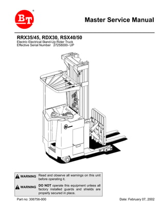
Read and observe all warnings on this unit
before operating it.
DO NOT operate this equipment unless all
factory installed guards and shields are
properly secured in place.
WARNING
WARNING
Part no: 306756-000 Date: February 07, 2002
RRX35/45, RDX30, RSX40/50
Electric Electrical Stand-Up Rider Truck
Effective Serial Number 27258000- UP
Fron
Return
2. Standard Codes
F-code Section C-code
Version no T-code
000
1Master Service Manual 2000-08-04© BT Prime-Mover, Inc.
Standard Codes
B-Code = Business area
F-Code = Product family
T-Code = Product type
C-Code = Component function
Worksheet standard
W-Code = Working code
R-Code = Reason code
SO-Code = Assortment
F-Code List
PS - Powered Pallet Stacker
T-Code List
Code Model
395 RRX35
396 RRX45
397 RDX30
398 RSX40
399 RSX50
C-Code List
No Function Group C-Code
0 Chassis 0000
1 Motors 1000
2 Drive Gear / Transmission 2000
3 Brake / Wheel System 3000
4 Steering System 4000
5 Electrical System 5000
Return
3. 000
Version no T-code
F-code Section C-code
Standard Codes
2 Master Service Manual 2000-08-04
6 Hydraulic / Pneumatic System 6000
7 Operating Function-lifting Mast / Cylinders 7000
8 Peripheral / Installation Equipment 8000
9 Options / Attachments 9000
Return
4. Table of Contents
© BT Prime-Mover, Inc. 32001-10-12Master Service Manual
Standard Codes ............................................................................................. 1
Warning Symbols ......................................................................................... 15
Warning Levels ......................................................................................... 15
Prohibitory Symbols .................................................................................... 16
Ordinance Symbols .................................................................................. 16
Safety ............................................................................................................ 17
General Safety .......................................................................................... 17
Battery Safety ............................................................................................... 21
Static Safety .................................................................................................. 26
Welding Safety ............................................................................................. 27
Introduction, Service Manual ...................................................................... 29
Contents, Section M ..................................................................................... 31
Machine Information ................................................................................. 31
General Product Information ...................................................................... 33
Presentation of the Rider Trucks. ............................................................. 33
Main Components ..................................................................................... 42
Inch (SAE) and Metric Fasteners ............................................................... 45
Introduction ............................................................................................... 45
Nomenclature, Threads ............................................................................ 46
Strength Identification ............................................................................... 47
Conversion of Metric and English Units .................................................... 55
Technical Service Data ................................................................................ 57
Ordering Spare Parts ................................................................................... 61
Contents, Section P ..................................................................................... 63
Planned Maintenance ............................................................................... 63
Introduction, Maintenance .......................................................................... 65
Jacking Truck Off The Floor ..................................................................... 66
Lubricants ................................................................................................. 68
Service Schedule ......................................................................................... 71
Planned Maintenance Schedule ............................................................... 71
Table of Contents
Return
5. Table of Contents
4 2001-10-12Master Service Manual
Planned Maintenance Procedures ............................................................ 76
Lubrication Chart ......................................................................................... 83
Oil and Grease Specifications .................................................................... 84
Approved Oils and Grease ....................................................................... 84
Grease Location Points ............................................................................ 85
Mast Adjustment Points ............................................................................ 86
Contents, Section S ..................................................................................... 87
Service Instructions .................................................................................. 87
Troubleshooting Guidelines ....................................................................... 89
General ..................................................................................................... 89
Electrical ................................................................................................... 91
Hydraulic ................................................................................................... 96
Definitions ................................................................................................. 97
Chassis ......................................................................................................... 99
General ..................................................................................................... 99
Dash ........................................................................................................ 100
Motor Compartment Door ........................................................................ 101
Left-Hand Side Panel ............................................................................... 102
Operator Compartment Panel .................................................................. 103
Main Card Access Panel ......................................................................... 103
Battery Compartment ................................................................................. 105
Battery Retainer Plates ............................................................................ 106
Battery Rollers ......................................................................................... 106
Driver Controls ............................................................................................ 107
Brake Pedal, RSX40/RRX35 ........................................................................ 109
Pedal Removal ........................................................................................ 110
Pedal Bearing Replacement .................................................................... 111
Pedal Adjustment ..................................................................................... 111
Brake Pedal, RSX50/RRX45/RDX30 ........................................................... 112
Pedal Removal ........................................................................................ 113
Pedal Bearing Replacement .................................................................... 114
Pedal Adjustment ..................................................................................... 114
Overhead Guard .......................................................................................... 115
Decals ........................................................................................................... 117
Return
6. Table of Contents
© BT Prime-Mover, Inc. 52001-10-12Master Service Manual
Decal with Protective Sheet ..................................................................... 117
Decal without Protective Sheet ................................................................ 117
Steering Motor ............................................................................................. 121
Removal ................................................................................................... 121
Installation ................................................................................................ 121
Steering Motor Gear Replacement .......................................................... 122
Fan Motor ..................................................................................................... 123
Upper Electrical Compartment Fan ......................................................... 123
Operator Fan ........................................................................................... 124
Motor Maintenance
Schedule/Troubleshooting ......................................................................... 125
General Information ................................................................................. 125
Operating Conditions ............................................................................... 125
Troubleshooting ....................................................................................... 126
Motor Repair ................................................................................................ 133
Disassembly ............................................................................................ 133
Motor Inspection ...................................................................................... 135
Pump Motor ................................................................................................. 141
Mounting Points ....................................................................................... 141
Repair ...................................................................................................... 145
Drive Motor .................................................................................................. 149
Mounting Points ....................................................................................... 149
Repair ...................................................................................................... 152
Transmission ............................................................................................... 155
Mounting Points ....................................................................................... 155
Repair ...................................................................................................... 159
Disassemble ............................................................................................ 161
Assembly ................................................................................................. 165
Axle Sealing Ring .................................................................................... 174
Leakage ................................................................................................... 176
Wheel Bolt ............................................................................................... 178
Electromagnetic Brake ............................................................................... 179
Removal ................................................................................................... 179
Installation ................................................................................................ 181
Adjustments ............................................................................................. 182
Coil Check On Brake ............................................................................... 183
Electromagnetic Brake, Armature and Magnetic Coil .............................. 183
Return
7. Table of Contents
6 2001-10-12Master Service Manual
Brake Friction Plate ................................................................................. 184
Drive Wheel .................................................................................................. 185
Removal ................................................................................................... 186
Installation ................................................................................................ 186
Tire Pressing Procedure .......................................................................... 187
Non-Braking Caster Wheel, RRX35/RSX40 ............................................... 189
Caster Pivot ............................................................................................. 191
Thrust Bearing ......................................................................................... 193
Caster Springs ......................................................................................... 195
Caster Stops ............................................................................................ 197
Non-Braking Caster Assembly, RRX35/RSX40 ........................................ 199
Removal ................................................................................................... 200
Installation ................................................................................................ 200
Braking Caster Wheel, RRX45/RDX30/RSX50 .......................................... 201
Removal ................................................................................................... 203
Braking Caster Assembly, RRX45/RDX30/RSX50 .................................... 205
Removal ................................................................................................... 207
Installation ................................................................................................ 208
Load Wheels, Sizes 4 X 3, 5 X 4, and 5 X 3 .............................................. 209
Removal ................................................................................................... 211
Installation ................................................................................................ 212
Load Wheels, Size 10.5 X 3.5 ..................................................................... 213
Removal ................................................................................................... 214
Installation ................................................................................................ 214
Steering Arm / Wheel / Lever ..................................................................... 215
Control Pod .............................................................................................. 217
Steering Wheel ........................................................................................ 218
Steering Tach .......................................................................................... 219
Steering Bearing ......................................................................................... 221
Removal ................................................................................................... 222
Installation ................................................................................................ 222
Electrical Functions .................................................................................... 223
General .................................................................................................... 223
Start Up .................................................................................................... 227
Steering Components .............................................................................. 231
Return
8. Table of Contents
© BT Prime-Mover, Inc. 72001-10-12Master Service Manual
Brake Release ......................................................................................... 237
Direction Selection ................................................................................... 239
Travel Request, Forks First ..................................................................... 241
Travel Request, Forks Trailing ................................................................. 245
Plug Braking ............................................................................................ 250
12-Volt Power Supply .............................................................................. 254
7.35-Volt Power Supplies ........................................................................ 255
Limit Switches .......................................................................................... 258
Height Indicator ........................................................................................ 262
Drive Motor Brush Wear Indicator Switches ............................................ 264
Pump Motor Brush Indicator Switch ........................................................ 265
Safety Check ........................................................................................... 266
Shunt Power Cable .................................................................................. 268
Electrical Symbols ...................................................................................... 275
Electrical Schematics (Serial numbers 27163000-28105000) .................. 277
Circuit Diagram 1(11) ............................................................................... 277
Circuit Diagram 2(11) ............................................................................... 278
Circuit Diagram 3(11) ............................................................................... 279
Circuit Diagram 4(11) ............................................................................... 280
Circuit Diagram 5(11) ............................................................................... 281
Circuit Diagram 6(11) ............................................................................... 282
Circuit Diagram 7(11) ............................................................................... 283
Circuit Diagram 8(11) ............................................................................... 284
Circuit Diagram 9(11) ............................................................................... 285
Circuit Diagram 10(11) ............................................................................. 286
Circuit Diagram 11(11) ............................................................................. 287
Electrical Schematics (Serial numbers 28105001-28126000) .................. 289
Circuit Diagram 1(12) ............................................................................... 289
Circuit Diagram 2(12) ............................................................................... 290
Circuit Diagram 3(12) ............................................................................... 291
Circuit Diagram 4(12) ............................................................................... 292
Circuit Diagram 5(12) ............................................................................... 293
Circuit Diagram 6(12) ............................................................................... 294
Circuit Diagram 7(12) ............................................................................... 295
Circuit Diagram 8(12) ............................................................................... 296
Circuit Diagram 9(12) ............................................................................... 297
Circuit Diagram 10(12) ............................................................................. 298
Circuit Diagram 11(12) ............................................................................. 299
Circuit Diagram 12(12) ............................................................................. 300
Electrical Schematics (Serial numbers 28126001-31285000) .................. 301
Circuit Diagram 1(12) ............................................................................... 301
Return
9. Table of Contents
8 2001-10-12Master Service Manual
Circuit Diagram 2(12) ............................................................................... 302
Circuit Diagram 3(12) ............................................................................... 303
Circuit Diagram 4(12) ............................................................................... 304
Circuit Diagram 5(12) ............................................................................... 305
Circuit Diagram 6(12) ............................................................................... 306
Circuit Diagram 7(12) ............................................................................... 307
Circuit Diagram 8(12) ............................................................................... 308
Circuit Diagram 9(12) ............................................................................... 309
Circuit Diagram 10(12) ............................................................................. 310
Circuit Diagram 11(12) ............................................................................. 311
Circuit Diagram 12(12) ............................................................................. 312
Electrical Schematics (Serial numbers 31285001-UP) ............................. 313
Circuit Diagram 1(12) ............................................................................... 313
Circuit Diagram 2(12) ............................................................................... 314
Circuit Diagram 3(12) ............................................................................... 315
Circuit Diagram 4(12) ............................................................................... 316
Circuit Diagram 5(12) ............................................................................... 317
Circuit Diagram 6(12) ............................................................................... 318
Circuit Diagram 7(12) ............................................................................... 319
Circuit Diagram 8(12) ............................................................................... 320
Circuit Diagram 9(12) ............................................................................... 321
Circuit Diagram 10(12) ............................................................................. 322
Circuit Diagram 11(12) ............................................................................. 323
Circuit Diagram 12(12) ............................................................................. 324
Battery .......................................................................................................... 325
Removal ................................................................................................... 325
Installation ................................................................................................ 325
Battery Maintenance ................................................................................ 326
Storage .................................................................................................... 328
Battery History Record ............................................................................. 328
Light Assemblies ........................................................................................ 329
Overhead Guard Lights (Option) ............................................................. 329
Warning Lights (Option) ........................................................................... 330
Working Lights (Option) ........................................................................... 331
Travel Alarm (Option) .............................................................................. 332
Operator Fan (Option) ............................................................................. 333
Horn .............................................................................................................. 335
Removal ................................................................................................... 335
Installation ................................................................................................ 335
Start/Stop Switches .................................................................................... 337
Return
10. Table of Contents
© BT Prime-Mover, Inc. 92001-10-12Master Service Manual
General .................................................................................................... 337
Key Switch (S17) ..................................................................................... 337
Emergency Disconnect Switch (S21) ...................................................... 339
Battery Connector ....................................................................................... 341
Location ................................................................................................... 341
Inspection ................................................................................................ 341
Installation ................................................................................................ 342
Mast Switch (S31) ........................................................................................ 343
General .................................................................................................... 343
Control Cable and Harness ........................................................................ 347
Fuses ....................................................................................................... 347
Wiring ....................................................................................................... 348
Contactors ................................................................................................... 351
General .................................................................................................... 351
Direction Contactors ................................................................................ 352
Lift Bypass Contactor
(RRX45/RSX50/RDX30) .......................................................................... 354
Main Contactor ........................................................................................ 356
Transistor Panel (Drive) .............................................................................. 359
Motor Connections ................................................................................... 360
Transistor Panel (Lift) ................................................................................. 361
Circuit Check, Drive Only ......................................................................... 363
Micro Switches ............................................................................................ 365
General .................................................................................................... 365
Lift Limit Override Switch (S33) Optional ................................................. 366
Optional Light and Fan Switches (S96, S97 and S99) ............................ 367
Main Electronic Card .................................................................................. 369
Connectivity to Truck ............................................................................... 369
Transistor Controller Replacement .......................................................... 370
Removal ................................................................................................... 374
Installation ................................................................................................ 374
Display ..................................................................................................... 380
Time ......................................................................................................... 381
Effect on Truck ......................................................................................... 381
Running time ............................................................................................ 382
RV2 Adjustment Procedure ..................................................................... 382
Adjustment Procedures for Setting Brake Switch and Brake Transducer 383
Return
11. Table of Contents
10 2001-10-12Master Service Manual
Battery Discharge Indicator Parameter Adjustment ................................. 384
A5 Jumper Harness Kit Installation (Serial numbers 28126000 - below) 390
WarningCaution Codes ........................................................................... 393
Error Codes ............................................................................................. 395
Programming Parameter ......................................................................... 401
Switches and Sensors ................................................................................ 411
General .................................................................................................... 411
Platform (Right Foot) Switch (S108) ........................................................ 411
Staging Switch (S45) ............................................................................... 413
Wheel Direction Sensor ........................................................................... 415
Steer Proximity Sensors A and B (S66 and S67) .................................... 417
Drive Motor Speed(S64)/Direction Sensors (S125) ................................. 419
Hydraulic System ........................................................................................ 421
Operation ................................................................................................. 421
RRX35 Hydraulic Schematic ................................................................... 442
RRX45 Hydraulic Schematic ................................................................... 443
RDX30 Hydraulic Schematic ................................................................... 444
RSX40 Hydraulic Schematic .................................................................... 445
RSX50 Hydraulic Schematic .................................................................... 446
Hydraulic Fluid ............................................................................................ 447
Hydraulic Fluid Selection ......................................................................... 447
Changing Hydraulic System Fluid ............................................................ 447
System Draining ...................................................................................... 448
Refilling System ....................................................................................... 449
Bleeding Hydraulic System ...................................................................... 450
Hydraulic Tank ............................................................................................ 452
Removal ................................................................................................... 453
Installation ................................................................................................ 454
Hydraulic Filter Assembly .......................................................................... 456
Hydraulic Filter ......................................................................................... 457
Hydraulic Filter Adapter ........................................................................... 458
Hydraulic Pump .......................................................................................... 460
Removal ................................................................................................... 460
Repair ...................................................................................................... 460
Control Valve ............................................................................................... 461
Removal .................................................................................................. 461
Installation ................................................................................................ 461
Return
12. Table of Contents
© BT Prime-Mover, Inc. 112001-10-12Master Service Manual
Control Valve Assembly ............................................................................. 466
Repair ...................................................................................................... 468
Staging Cylinder, Three Stage Mast .......................................................... 473
Bearing Removal ..................................................................................... 474
Disassembly ............................................................................................ 475
Assembly ................................................................................................. 475
Installation ................................................................................................ 475
Freelift Cylinder, Three Stage Mast ........................................................... 477
Removal ................................................................................................... 479
Disassembly ............................................................................................ 480
Assembly ................................................................................................. 480
Installation ................................................................................................ 480
Reach Cylinder Assembly .......................................................................... 481
Removal ................................................................................................... 483
Disassembly ............................................................................................ 484
Inspection ................................................................................................ 485
Assembly ................................................................................................. 486
Installation ................................................................................................ 487
Tilt Cylinder Assembly, RRX35/RSX40/RSX50 ......................................... 489
Removal ................................................................................................... 490
Disassembly ............................................................................................ 491
Inspection ................................................................................................ 492
Assembly ................................................................................................. 493
Installation ................................................................................................ 494
Tilt Cylinder Assembly, RRX45/RDX30 ..................................................... 495
Removal ................................................................................................... 497
Disassembly ............................................................................................ 498
Inspection ................................................................................................ 499
Assembly ................................................................................................. 500
Installation ................................................................................................ 501
Mast, 3 Stage ............................................................................................... 503
Shimming Carriage with Mast on Truck ................................................... 507
Three Stage Mast .................................................................................... 509
Lift Chain .................................................................................................. 514
Lifting Gear (Crosshead) ............................................................................ 523
Lifting Gear Repair ................................................................................... 525
Sideshifter, RRX35/45/RDX30 .................................................................... 527
Return
13. Table of Contents
12 2001-10-12Master Service Manual
Mounting Instructions ............................................................................... 529
Operation and Maintenance .................................................................... 530
Sideshifter, RRX35/45/RSX40/50/RDX30 ................................................... 533
Mounting Instructions ............................................................................... 535
Operation ................................................................................................. 536
Maintenance ............................................................................................ 536
Troubleshooting ....................................................................................... 540
Single Reach, RRX35 .................................................................................. 541
Maintenance ............................................................................................ 547
Reach Repair ........................................................................................... 552
Carriage Bumpers .................................................................................... 556
Fork Carriage Pivot Pins .......................................................................... 558
Carriage Roller Bearings ......................................................................... 558
Single Reach, RRX45 .................................................................................. 559
Maintenance ............................................................................................ 559
Reach Repair ........................................................................................... 567
Fork Carriage Pivot Pins .......................................................................... 571
Carriage Roller Bearings ......................................................................... 572
Double Reach Mechanism, RDX30 ............................................................ 573
Theory of Operation ................................................................................. 575
Maintenance ............................................................................................ 575
Troubleshooting ....................................................................................... 575
Repair ...................................................................................................... 575
Rebuild ..................................................................................................... 575
Forks ............................................................................................................ 577
Removal ................................................................................................... 579
Inspection ................................................................................................ 579
Installation ................................................................................................ 580
Load Indicator ............................................................................................. 581
Load Indicator ............................................................................................. 583
Pulse Sensor ........................................................................................... 585
Height Indicator and Preset Selector ....................................................... 587
General .................................................................................................... 588
Operation ................................................................................................. 588
Preset Height ........................................................................................... 589
Display ..................................................................................................... 590
Display Symbols Description ................................................................... 591
Return
14. Table of Contents
© BT Prime-Mover, Inc. 132001-10-12Master Service Manual
Programming ........................................................................................... 592
Load Backrest ............................................................................................. 601
Removal ................................................................................................... 604
Installation ................................................................................................ 604
Return
15. Warning Symbols
PS
F-code Section C-code
Version no T-code
001
15Master Service Manual 2000-08-04© BT Prime-Mover, Inc.
Warning Symbols
Always follow the warnings given in this Service Manual
and on the truck to avoid accidents and incidents from
occurring.
1. Warning Levels
Warning levels
Warning texts are given in four levels and provide information
on the risks, describe the consequences, and instruct how to
avoid accidents.
DANGER
Warns that an accident will occur if the instructions are
not followed.
The consequences are serious personal injury or
possibly death, and/or extremely large material damage.
WARNING
Warns that an accident can occur if the instructions are
not followed.
The consequences are serious personal injury or
possibly death, and/or large material damage.
CAUTION
Warns that an accident can occur if the instructions are
not followed.
The consequences are personal injury and/or material
damage.
NOTE!
Marks the risk of an accident or breakdown if the
instructions are not followed.
Return
16. PS
001
Version no T-code
F-code Section C-code
Prohibitory Symbols
16 Master Service Manual 2000-08-04
Prohibitory Symbols
NO SMOKING
If smoking occurs in situations where a restriction against
smoking is stated, a serious accident can occur.
OPEN FLAMES PROHIBITED
If open flames are used in situations where open flames are
prohibited, a serious accident can occur.
GENERAL PROHIBITION
If the prohibition is ignored, a serious accident can occur.
1. Ordinance Symbols
SAFETY SHOES
When the directive for safety shoes is given, safety shoes
shall always be worn to avoid personal injury.
PROTECTIVE GLASSES
When the directive for protective glasses is given,
protective glasses shall always be worn to avoid personal
injury.
Return
17. Safety
PS
F-code Section C-code
Version no T-code
001
17Master Service Manual 2000-08-04© BT Prime-Mover, Inc.
Safety
1. General Safety
Do NOT operate or work on this truck unless trained,
qualified, and authorized to do so and have read the
Operator’s Manual.
Know the controls on the truck and what they do.
Do NOT operate truck if it needs repair or if it is in any way
unsafe.
Return
18. PS
001
Version no T-code
F-code Section C-code
Safety
18 Master Service Manual 2000-08-04
Operate truck only from the position of the Operator.
Before working on this truck always turn key switch to OFF
and disconnect battery connector on truck (unless this
manual states otherwise).
Do NOT wear watches, rings, or jewelry when working on
truck.
Follow the scheduled lubrication, maintenance, and
inspection steps.
Return
19. Thank you very much for
your reading. Please Click
Here. Then Get COMPLETE
MANUAL. NO WAITING
NOTE:
If there is no response to
click on the link above,
please download the PDF
document first and then
click on it.
20. Safety
PS
F-code Section C-code
Version no T-code
001
19Master Service Manual 2000-08-04© BT Prime-Mover, Inc.
Follow exactly the safety and repair instructions in this
manual. Do NOT take “shortcuts”.
Do NOT Use an open flame near the truck.
Do NOT use gasoline or other flammable liquids for cleaning
parts.
Clean up any hydraulic fluid, oil, or grease that has leaked or
spilled on the floor.
Return
21. PS
001
Version no T-code
F-code Section C-code
Safety
20 Master Service Manual 2000-08-04
Always operate and park truck indoors.
Do NOT wash truck with a hose.
Do NOT add to or modify truck without written approval from
BT Prime-Mover, Inc.
Return
22. Battery Safety
PS
F-code Section C-code
Version no T-code
001
21Master Service Manual 2000-08-04© BT Prime-Mover, Inc.
Battery Safety
Read, understand and follow procedures, recommendations
and specifications in the battery and battery charger manuals
from the manufacturer.
As a battery is being charged, an explosive
gas mixture forms within and around each
cell. If the area is not properly ventilated,
this explosive gas can remain in or around
the battery for several hours after charging.
Be sure there are no open flames or sparks
in the charging area. An open flame or
spark can ignite this gas, resulting in
serious damage or injury.
Battery electrolyte is a solution of sulfuric
acid and water. Battery acid causes burns.
Should any electrolyte come in contact with
clothing or skin, flush the area immediately
with cold water. Should the solution get on
the face or in the eyes, flush the area with
cold water and receive medical attention
immediately.
WARNING
WARNING
Return