SlideShare a Scribd company logo
1 of 29
Download to read offline
Copyright © 2001 CNH America LLC.
All rights reserved.
Printed in U.S.A.
Issued August, 2001 Revised July, 2005
CNH America LLC.
700 State Street
Racine, WI 53404 U.S.A. Bur 6-42725
521D Loader
Service Manual
6-40745
Table of Contents
Description Section No. Form No.
General Tab 1
Section Index - General 6-42730
Standard Torque Specifications 1001 8-71603
Fluids and Lubricants 1002 6-40762
Metric Conversion Chart 1003 7-52950
Loctite Product Chart 8-98902
Engines Tab 2
Section Index - Engines 6-42281
Engine and Radiator Removal and Installation 2000 6-42290
Engine and Radiator Removal and Installation P.I.N. JEE0135501 and Above 2000 6-48920
Stall Tests 2002 6-40771
For Engine Repair, See the Engine Service Manual 6-74500
Fuel System Tab 3
Section Index - Fuel System 6-42300
For Fuel System Repair, See the Engine Service Manual 6-74500
Electrical Tab 4
Section Index - Electrical 6-42311
Removal and Installation of Starter and Alternator 4001 6-42321
Electrical Specifications and Troubleshooting 4002 6-40782
Electrical Specifications and Troubleshooting P.I.N. JEE0135501 and Above 4002 6-48930
Batteries 4003 6-42330
Information and Diagnostic Center 4005 6-42352
Alternator - 65 Ampere 4007 7-12260
Alternator - 45 Ampere 4008 6-42360
Bur 6-42725 Revised 7-05 Printed in U.S.A.
Steering Tab 5
Section Index - Steering 6-42370
Removal and Installation of Steering Components 5001 6-42380
Steering Specifications, Pressure Checks, and Troubleshooting 5002 6-40790
Steering Control Valve 5003 6-42390
Steering Priority Valve 5004 6-42400
Steering Cylinders 5005 6-42410
Center Pivot 5006 6-42420
Auxiliary Steering Motor and Pump 5008 6-42430
Power Train Tab 6
Section Index - Power Train 6-42442
Removal and Installation of Power Train Components 6001 6-42451
Transmission Specifications, Pressure Checks, and Troubleshooting 6002 6-40800
Transmission 6003 6-42460
Front and Rear Axle 6004 6-42470
Front and Rear Axle P.I.N. JEE0135501 and Above 6004 6-48970
Drive Shafts, Center Bearing, and Universal Joints 6005 6-42480
Wheels and Tires 6006 6-42490
Transmission Control Valve 6007 6-42500
Brakes Tab 7
Section Index - Brakes 6-42510
Removal and Installation of Brake Components 7001 6-42521
Hydraulic Brake Troubleshooting 7002 6-40811
Brake Accumulators 7004 6-42531
Parking Brake 7008 6-42540
NOTE: For parking brake and brake pedal adjustments, see Section 9001.
Hydraulics Tab 8
Section Index - Hydraulics 6-42551
Removal and Installation of Hydraulic Components 8001 6-42562
Hydraulic Specifications, Troubleshooting, and Pressure Checks 8002 6-40822
Cleaning the Hydraulic System 8003 7-49640
Loader Control Vale 8005 6-42580
Cylinders 8006 6-42591
Coupler Solenoid Locking Valve 8007 6-42600
Pilot Pressure Accumulator and Ride Control Accumulator 8013 6-42621
Ride Control Valve 8014 6-44751
521D Loader
Service Manual
6-40745
Table of Contents
Description Section No. Form No.
Copyright © 2001 CNH America LLC.
All rights reserved.
Printed in U.S.A.
Issued August, 2001 Revised July, 2005
CNH America LLC.
700 State Street
Racine, WI 53404 U.S.A. Bur 6-42725
NOTE: Case Corporation reserves the right to make improvements in design or
changes in specifications at any time without incurring any obligation to install
them on units previously sold.
Mounted Equipment Tab 9
Section Index - Mounted Equipment 6-42640
Pedals and Levers 9001 6-40830
Air Conditioning Troubleshooting and System Checks For Systems with HFC-134a
Refrigerant
9002 6-42650
Air Conditioner System Service 9003 6-42660
Removal and Installation of Air Conditioning Components For Systems with
HFC-134a Refrigerant 9004 6-42671
Loader 9006 6-42691
ROPS Cab and ROPS Canopy 9007 6-42700
Cab Glass Installation 9010 6-42710
Electrical Schematic Foldouts and Hydraulic Schematic Foldout In Rear Pocket 6-40841
Electrical Schematic Foldouts and Hydraulic Schematic Foldout P.I.N
JEE0135501 and Above
In Rear Pocket 6-49280
521D Loader
Service Manual
6-40745
Table of Contents
Description Section No. Form No.
CASE CORPORATION
700 State Street
Racine, WI 53404 U.S.A.
CASE CANADA CORPORATION
3350 South Service Road
Hamilton, ON L7N 3M6 CANADA Bur 6-42730
Copyright © 2001 Case Corporation
Printed in U.S.A.
August, 2001
SECTION INDEX
GENERAL
Standard Torque Specifications. . . . . . . . . . . . . . . . . . . . . . . . . . . . . . . . . . . . . . . . . . . . . . . . . . . . . . . . . . . . . 1001
Fluids and Lubricants . . . . . . . . . . . . . . . . . . . . . . . . . . . . . . . . . . . . . . . . . . . . . . . . . . . . . . . . . . . . . . . . . . . . .1002
Metric Conversion Chart . . . . . . . . . . . . . . . . . . . . . . . . . . . . . . . . . . . . . . . . . . . . . . . . . . . . . . . . . . . . . . . . . . .1003
Loctite Product Chart
Section Title Section Number
1001-3
Bur 8-71603 Revised 4-04 Printed in U.S.A.
TORQUE SPECIFICATIONS - DECIMAL HARDWARE
Use the torques in this chart when special torques
are not given. These torques apply to fasteners with
both UNC and UNF threads as received from
suppliers dry, or when lubricated with engine oil. Not
applicable if special graphities, Molydisulfide
greases, or other extreme pressure lubricants are
used.
Grade 5 Bolts, Nuts, and Studs
Size
Pound-
Inches
Newton
metres
1/4 inch 108 to 132 12 to 15
5/16 inch 204 to 252 23 to 28
3/8 inch 420 to 504 48 to 57
Size
Pound-
Feet
Newton
metres
7/16 inch 54 to 64 73 to 87
1/2 inch 80 to 96 109 to 130
9/16 inch 110 to 132 149 to 179
5/8 inch 150 to 180 203 to 244
3/4 inch 270 to 324 366 to 439
7/8 inch 400 to 480 542 to 651
1.0 inch 580 to 696 787 to 944
1-1/8 inch 800 to 880 1085 to 1193
1-1/4 inch 1120 to 1240 1519 to 1681
1-3/8 inch 1460 to 1680 1980 to 2278
1-1/2 inch 1940 to 2200 2631 to 2983
Grade 8 Bolts, Nuts, and Studs
Size
Pound-
Inches
Newton
metres
1/4 inch 144 to 180 16 to 20
5/16 inch 288 to 348 33 to 39
3/8 inch 540 to 648 61 to 73
Size
Pound-
Feet
Newton
metres
7/16 inch 70 to 84 95 to 114
1/2 inch 110 to 132 149 to 179
9/16 inch 160 to 192 217 to 260
5/8 inch 220 to 264 298 to 358
3/4 inch 380 to 456 515 to 618
7/8 inch 600 to 720 814 to 976
1.0 inch 900 to 1080 1220 to 1465
1-1/8 inch 1280 to 1440 1736 to 1953
1-1/4 inch 1820 to 2000 2468 to 2712
1-3/8 inch 2380 to 2720 3227 to 3688
1-1/2 inch 3160 to 3560 4285 to 4827
NOTE: Use thick nuts with Grade 8 bolts.
1001-4
Bur 8-71603 Revised 4-04 Printed in U.S.A.
TORQUE SPECIFICATIONS - METRIC HARDWARE
Use the following torques when specifications are not
given.
These values apply to fasteners with coarse threads
as received from supplier, plated or unplated, or
when lubricated with engine oil. These values do not
apply if graphite or Molydisulfide grease or oil is
used.
Grade 12.9 Bolts, Nuts, and Studs
Usually the torque values specified for grade 10.9
fasteners can be used satisfactorily on grade 12.9
fasteners.
Grade 8.8 Bolts, Nuts, and Studs
Size
Pound-
Inches
Newton
metres
M4 24 to 36 3 to 4
M5 60 to 72 7 to 8
M6 96 to 108 11 to 12
M8 228 to 276 26 to 31
M10 456 to 540 52 to 61
Size
Pound-
Feet
Newton
metres
M12 66 to 79 90 to 107
M14 106 to 127 144 to 172
M16 160 to 200 217 to 271
M20 320 to 380 434 to 515
M24 500 to 600 675 to 815
M30 920 to 1100 1250 to 1500
M36 1600 to 1950 2175 to 2600
8.8
Grade 10.9 Bolts, Nuts, and Studs
Size
Pound-
Inches
Newton
metres
M4 36 to 48 4 to 5
M5 84 to 96 9 to 11
M6 132 to 156 15 to 18
M8 324 to 384 37 to 43
Size
Pound-
Feet
Newton
metres
M10 54 to 64 73 to 87
M12 93 to 112 125 to 150
M14 149 to 179 200 to 245
M16 230 to 280 310 to 380
M20 450 to 540 610 to 730
M24 780 to 940 1050 to 1275
M30 1470 to 1770 2000 to 2400
M36 2580 to 3090 3500 to 4200
10.9
12.9
1001-5
Bur 8-71603 Revised 4-04 Printed in U.S.A.
TORQUE SPECIFICATIONS - STEEL HYDRAULIC FITTINGS
Tube OD
Hose ID
Thread
Size
Pound-
Inches
Newton
metres
37 Degree Flare Fitting
1/4 inch
6.4 mm
7/16-20 72 to 144 8 to 16
5/16 inch
7.9 mm
1/2-20 96 to 192 11 to 22
3/8 inch
9.5 mm
9/16-18 120 to 300 14 to 34
1/2 inch
12.7 mm
3/4-16 180 to 504 20 to 57
5/8 inch
15.9 mm
7/8-14 300 to 696 34 to 79
Tube OD
Hose ID
Thread
Size
Pound-
Feet
Newton
metres
3/4 inch
19.0 mm
1-1/16-12 40 to 80 54 to 108
7/8 inch
22.2 mm
1-3/16-12 60 to 100 81 to 135
1.0 inch
25.4 mm
1-5/16-12 75 to 117 102 to 158
1-1/4 inch
31.8 mm
1-5/8-12 125 to 165 169 to 223
1-1/2 inch
38.1 mm
1-7/8-12 210 to 250 285 to 338
Split Flange Mounting Bolts
Size
Pound-
Inches
Newton
metres
5/16-18 180 to 240 20 to 27
3/8-16 240 to 300 27 to 34
7/16-14 420 to 540 47 to 61
Size
Pound-
Feet
Newton
metres
1/2-13 55 to 65 74 to 88
5/8-11 140 to 150 190 to 203
Tube OD
Hose ID
Thread
Size
Pound-
Inches
Newton
metres
Straight Threads with O-ring
1/4 inch
6.4 mm
7/16-20 144 to 228 16 to 26
5/16 inch
7.9 mm
1/2-20 192 to 300 22 to 34
3/8 inch
9.5 mm
9/16-18 300 to 480 34 to 54
1/2 inch
12.7 mm
3/4-16 540 to 804 57 to 91
Tube OD
Hose ID
Thread
Size
Pound-
Feet
Newton
metres
5/8 inch
15.9 mm
7/8-14 58 to 92 79 to 124
3/4 inch
19.0 mm
1-1/16-12 80 to 128 108 to 174
7/8 inch
22.2 mm
1-3/16-12 100 to 160 136 to 216
1.0 inch
25.4 mm
1-5/16-12 117 to 187 159 to 253
1-1/4 inch
31.8 mm
1-5/8-12 165 to 264 224 to 357
1-1/2 inch
38.1 mm
1-7/8-12 250 to 400 339 to 542
Section
2000
2000
CASE CORPORATION
700 State Street
Racine, WI 53404 U.S.A.
CASE CANADA CORPORATION
3350 South Service Road
Burlington, ON L7N 3M6 CANADA Bur 6-42290
Copyright © 2001 Case Corporation
Printed in U.S.A.
August,2001
ENGINE AND RADIATOR REMOVAL AND INSTALLATION
2000-3
Bur 6-42290 Issued 8-01 Printed in U.S.A.
ENGINE
Removal
STEP 1
Park machine on a level surface and lower bucket to
floor. Stop engine. Actuate brake pedal several times
to discharge brake accumulators. Put key switch in
ON position and move loader control lever back and
forth at least 30 times to release any pressure from
hydraulic circuit. Put key switch in OFF position.
STEP 2
BD00M030
Put articulation lock in LOCKED position.
STEP 3
Slowly loosen the filler cap for hydraulic reservoir to
release air pressure in hydraulic reservoir.
STEP 4
BD01D139
Open and raise hood. Put master disconnect switch
in OFF position.
STEP 5
BD01D141
Using a flat blade screwdriver or other suitable tool,
disengage bottom clip (1) from hood prop (2) and pull
bottom of prop from stud (3). Repeat to remove top of
prop from hood; remove prop then close hood.
STEP 6
BD01D142
Open screen.
STEP 7
BD01D143
Remove cotter pin and three washers.
3
2
1
2000-4
Bur 6-42290 Issued 8-01 Printed in U.S.A.
STEP 8
BD01D144
Remove four bolts (4) securing hinges of screen to
hood. Disconnect prop bar (5) from screen and
remove screen.
STEP 9
BD01D255
Connect a lifting strap to the hood handle and
connect lifting equipment to strap. Depress handle
latch and let hood raise.
STEP 10
BD01D256
Take up all slack in strap connected to hood handle.
STEP 11
BD01D145
Remove lock nut (6) securing LH spring (7) to hood.
Repeat to remove lock nut securing RH spring to
hood. Disconnect springs from hood; it may be
necessary to raise hood to disconnect springs from
hood.
STEP 12
BD01D258
At front RH side of hood, identify, tag, and disconnect
hood wiring harness connector from rear chassis
wiring harness connector.
STEP 13
Lower hood.
4
4
5
7
6
2000-5
Bur 6-42290 Issued 8-01 Printed in U.S.A.
STEP 14
BD01D149
Install two lifting eyes and connect lifting strap to
eyes.
STEP 15
BD01D254
Connect lifting equipment to the lifting straps.
STEP 16
BD01D147
Remove two nuts and bolts and four washers
securing hood.
STEP 17
BD01D254
Carefully raise and remove hood from loader. Lower
hood onto suitable platform and disconnect lifting
equipment.
STEP 18
BD01D150
Tag and disconnect engine wiring harness connector
from air filter restriction switch.
STEP 19
BD01D152
Loosen clamp on air cleaner intake hose and remove
hose.
2000-6
Bur 6-42290 Issued 8-01 Printed in U.S.A.
STEP 20
BD01D154
Loosen clamp on turbocharger intake hose and
disconnect hose from turbocharger.
STEP 21
BD01D155
Remove bolt and washer securing front of battery
cover.
STEP 22
BD01D156
Loosen bolt. Slide battery cover forward and remove.
Repeat Steps 21 and 22 to remove RH battery cover.
STEP 23
BD01D158
Disconnect battery cable from LH battery negative
post. Put a plastic cap over the negative post.
STEP 24
BD01D161
Disconnect battery cable from RH battery positive
post. Put a plastic cap over the positive post.
STEP 25
BD01D162
Support air cleaner assembly (9) and remove two
lock nuts, washers, bolts (8), and washers. Remove
air cleaner and support as an assembly.
8
9
2000-7
Bur 6-42290 Issued 8-01 Printed in U.S.A.
STEP 26
BD01D165
Remove four bolts (10) and washers securing drive
belt guard (11) to master disconnect switch mounting
bracket and belt guard bracket.
STEP 27
BD01D168
Remove clamp securing elbow to muffler.
STEP 28
BD01D166
At front of engine, remove two bolts (12) and
washers securing wiring harness clamps and muffler
mounting bracket (13).
STEP 29
BD01D167
Support muffler and brackets and remove three bolts
and washers at rear of engine. Remove muffler and
brackets as an assembly from engine.
STEP 30
BD01D169
Loosen clamp and remove tube from turbocharger.
STEP 31
BD01D170
Loosen two clamps. Remove tube and hose as an
assembly.
10
11
12
12
13
2000-8
Bur 6-42290 Issued 8-01 Printed in U.S.A.
STEP 32
BD01D172
Loosen two clamps. Remove tube and hose as an
assembly.
STEP 33
BD01D177
Cut, remove, and discard tie strap securing LH rear
combination lamp wire. Identify, tag, and disconnect
rear chassis wiring harness connector from
combination lamp connector. Repeat this step for RH
rear combination lamp.
STEP 34
BD01D179
Connect lifting equipment to rear counterweight.
Take up all slack in lifting equipment.
STEP 35
BD01D178
Remove two nuts (14) and washers and two bolts
(15), washers, and nuts. Remove counterweight (16)
from loader and place on pallet.
STEP 36
BD01D164
Identify, tag, and disconnect the four connectors.
STEP 37
BD01D173
Pull rubber boot (17) back from starter B+ terminal
(18). Remove the nut, lock washer, and flat washer
from B+ terminal. Identify, tag, and disconnect the
wires from terminal.
14 14
15
15
16
17
18
2000-9
Bur 6-42290 Issued 8-01 Printed in U.S.A.
STEP 38
BD01D250
Identify and tag wire connected to starter solenoid
terminal. Pull the plastic cap from starter solenoid
terminal. Using a Phillips screwdriver, loosen
terminal screw and disconnect wire from terminal.
STEP 39
BD01D174
Remove nut (19) and washer. Disconnect ground
cables from engine ground stud. Move ground cables
away from engine. Remove bolt (20), lock washer,
and washer securing harness clamps to engine. Top
harness (21) is rear chassis wiring harness; bottom
harness (22) is engine wiring harness.
STEP 40
BD01D175
Remove nut and washer from engine ground stud.
Disconnect the five ground wires of the rear chassis
wiring harness from the stud.
STEP 41
BD01D176
BD01D257
Route rear chassis wiring harness to front of engine.
Cut, remove, and discard two tie straps then route
harness to RH side of engine compartment and away
from engine.
21
20
19
22
2000-10
Bur 6-42290 Issued 8-01 Printed in U.S.A.
STEP 42
BD00M031
Put a 37.8 liter (10 gallon) container below radiator
drain. Remove cap and drain coolant into container.
Install cap after coolant has drained.
STEP 43
BD01D184
Loosen two hose clamps. Remove bottom hose.
STEP 44
BD01D185
Loosen two hose clamps. Remove upper hose.
STEP 45
BD01D188
At top of cooling system frame, loosen two hose
clamps (23). Remove hose (24). Remove two nuts
(25) securing U-bolt (26). Remove U-bolt, clamp, and
spacer.
STEP 46
BD01D192
Remove two nuts securing U-bolt holding top coolant
pipe. Remove U-bolt, clamp, and spacer. Remove
top coolant pipe from cooling system frame.
STEP 47
BD01D189
Put a 12.7 mm (1/2 inch) drive breaker bar or ratchet
in bracket for automatic belt tensioner. Lift up on
breaker bar or ratchet to release drive belt tension
and remove belt.
23
23
24
26
25
2000-11
Bur 6-42290 Issued 8-01 Printed in U.S.A.
STEP 48
BD01D180
If loader is equipped with air conditioning, identify,
tag, and disconnect the engine wiring harness
connectors from air compressor clutch connector
(27) and high pressure switch connector (28).
Disconnect engine wiring harness connector from
disconnect switch wiring harness connector (29).
STEP 49
BD01D193
Support air conditioning compressor and remove four
bolts.
STEP 50
BD01D218
Install battery cover. Put air conditioning compressor
on battery cover.
STEP 51
BD00M031
Put a 18.9 liter (5 gallon) container below engine oil
drain. Remove cap and drain engine oil into
container. Install cap after oil has drained.
STEP 52
BD01D194
Disconnect hose from fitting installed in engine oil
pan. Install a plug in hose and a cap on fitting.
STEP 53
BD01D200
At front of engine, remove six bolts (30) securing
drive shaft (31) to engine coupling. Use a pry bar to
move drive shaft away from engine coupling.
27
28
29
30
31
2000-12
Bur 6-42290 Issued 8-01 Printed in U.S.A.
STEP 54
BD01D208
Disconnect engine wiring harness connector (32)
from transmission wiring harness bulkhead
connector. Remove clamp (33) securing fuel supply
hose to engine flywheel housing. Remove two
clamps (34) securing fuel return hose to engine.
STEP 55
BD01D209
If equipped, disconnect ether start nozzle from intake
manifold.
STEP 56
BD01D210
Cut, remove, and discard tie strap (35) securing
ether start tube (36). Move ether start tube away
from engine. Loosen clamp (37). Tag and disconnect
fuel supply hose (38) from primer pump. Plug hose
and cap fitting to prevent intrusion of foreign matter
into fuel system.
STEP 57
BD01D212
Remove nut and washer securing ball joint (39) to
throttle lever (40). Remove two socket head bolts
(41) and washers securing throttle bracket (42) to
engine. Move throttle bracket with throttle cable and
ball joint attached away from engine.
32
33
34
35
38
37
36
40
42
41
39
2000-13
Bur 6-42290 Issued 8-01 Printed in U.S.A.
STEP 58
BD01D215
Connect a vacuum pump to hydraulic reservoir. If a
vacuum pump is not available, drain the hydraulic oil
(hydraulic reservoir holds 68.5 liters (18 gallons) of
oil). Turn on vacuum pump (if available). Tag,
disconnect, and plug hoses connected to brake
pump. Plug hoses securely and cap fittings. Turn off
vacuum pump. Remove clamp securing fuel return
hose to engine.
STEP 59
BD01D216
Tag and disconnect fuel return hose. Plug hose and
cap fitting.
STEP 60
BD01D217
Remove nut (43), washer, and bolt securing clamp
(44) and engine oil pressure sender (45) to rear
chassis. Remove these parts as an assembly and
secure to engine using suitable means.
STEP 61
BD01D219
Remove two nuts and remove belt guard bracket.
STEP 62
BD01D203
If equipped, disconnect ether start solenoid
connector from engine wiring harness connector.
44
45
43
2000-14
Bur 6-42290 Issued 8-01 Printed in U.S.A.
STEP 63
BD01D220
Connect lifting equipment to engine lifting brackets.
Take up all slack in lifting equipment.
STEP 64
BD01D206
At front of engine, remove nut, bolt, and two washers
securing both sides of engine to rear chassis.
STEP 65
BD01D181
At rear of rear chassis, between fuel tank mounting
plate and rear chassis, remove bolt and washer
securing rear of engine to rear chassis.
STEP 66
Slowly raise engine from rear chassis. Be sure all
harness connections and hoses have been
disconnected and out of the way. Remove engine
from machine.
2000-15
Bur 6-42290 Issued 8-01 Printed in U.S.A.
Installation
STEP 67
BC01D128
If engine front rubber isolators require replacement,
remove and discard isolators (51 and 53). Install new
rubber isolator (53), washer (52), then rubber isolator
(51).
STEP 68
BC01D129
If engine rear rubber isolators require replacement,
remove and discard isolators (46 and 48) and spacer
(47). Install new rubber isolators (46 and 48) and
spacer (47) in rear chassis.
STEP 69
Slowly raise engine and move into position over rear
chassis. Be sure all harness connections and hoses
are out of the way then lower engine. Put washer
(54) between front rubber isolator (53) and rear
chassis. Install washer (55), bolt (56), washer (57),
and nut (58) in engine front isolators. Lower engine
into position. Install washer (49) and bolt (50) in rear
isolator.
STEP 70
BD01D206
At front of engine, tighten two bolts (56) to a torque of
244 to 298 Nm (180 to 220 lb-ft).
51. RUBBER ISOLATOR 56. BOLT
52. WASHER 57. WASHER
53. RUBBER ISOLATOR 58. NUT
54. WASHER A. ENGINE
55. WASHER B. REAR CHASSIS
52
55
51
56
A
53
54
B
57
58
46. RUBBER ISOLATOR 50. BOLT
47. SPACER A. ENGINE
48. RUBBER ISOLATOR B. REAR CHASSIS
49. WASHER
A
B
48
47
46
49
50
56
Thank you very much for
your reading. Please Click
Here. Then Get COMPLETE
MANUAL. NO WAITING
NOTE:
If there is no response to
click on the link above,
please download the PDF
document first and then
click on it.
2000-16
Bur 6-42290 Issued 8-01 Printed in U.S.A.
STEP 71
BD01D181
At rear of rear chassis, between fuel tank mounting
plate and rear chassis, tighten bolt (50) to a torque of
244 to 298 Nm (180 to 220 lb-ft).
STEP 72
BD01D220
Disconnect lifting equipment from engine lifting
brackets.
STEP 73
BD01D203
At right side of engine compartment, connect ether
start solenoid connector to engine wiring harness
connector if equipped.
STEP 74
BD01D219
Position belt guard bracket on rear chassis and
secure using two nuts.
STEP 75
BD01D217
Position engine oil pressure sender (45) and clamp
(44) on tab of rear chassis. Install nut (43), washer,
and bolt to secure clamp and engine oil pressure
sender to rear chassis.
STEP 76
BD01D216
Remove plug from hose and cap from fuel injection
pump fitting. Connect fuel return hose to fuel injection
pump following tag installed during removal. Position
and tighten clamp. Remove and discard tag.
50
44
45
43
2000-17
Bur 6-42290 Issued 8-01 Printed in U.S.A.
STEP 77
BD01D215
Install clamp to secure fuel return hose to engine.
Turn on vacuum pump connected to hydraulic
reservoir. Remove caps from fittings and plugs from
hoses. Connect hoses to brake pump following tags
installed during removal. Remove and discard tags.
Turn off and disconnect vacuum pump from hydraulic
reservoir.
STEP 78
BD01D212
Position throttle bracket with throttle cable and ball
joint attached on engine. Install two washers and
socket head bolts (41) to secure throttle bracket (42)
to engine. Connect ball joint (39) to throttle lever (40)
and secure with nut and washer.
STEP 79
BD01D209
If equipped, connect ether start nozzle to intake
manifold.
STEP 80
BD01D210
Remove cap from fitting and plug from hose.
Connect fuel supply hose (38) to primer pump
following tag installed during removal. Position and
tighten clamp (37). Remove and discard tag. Install a
new tie strap (35) to secure ether start tube (36).
STEP 81
BD01D208
Position fuel return hose and secure using two
clamps (34). Position fuel supply hose and secure
using clamp (33). Connect engine wiring harness
connector (32) to transmission wiring harness
bulkhead connector.
40
42
41
39
35
38
37
36
32
33
34
2000-18
Bur 6-42290 Issued 8-01 Printed in U.S.A.
STEP 82
BD01D200
At front of engine, position drive shaft (31) on engine
coupling. Install six bolts (30) to secure drive shaft
(31) to engine coupling. Tighten the six bolts to a
torque of 53 to 62 Nm (39 to 46 lb-ft).
STEP 83
BD01D194
Remove plug from oil drain hose and cap from fitting
installed in engine oil pan. Connect and tighten hose
to fitting.
STEP 84
BD01D193
If loader is equipped with air conditioning, position
and support air conditioning compressor and install
four bolts.
STEP 85
BD01D180
Connect engine wiring harness connector to
disconnect switch wiring harness connector (29). If
loader is equipped with air conditioning, connect the
engine wiring harness connectors to air compressor
clutch connector (27) and high pressure switch
connector (28) following tags installed during
removal. Remove and discard tags.
STEP 86
BD01D189
Route drive belt on pulleys then put a 12.7 mm (1/2
inch) drive breaker bar or ratchet in bracket for
automatic belt tensioner. Lift up on breaker bar or
ratchet and position drive belt then release belt
tensioner to put tension on drive belt.
30
31
27
28
29
2000-19
Bur 6-42290 Issued 8-01 Printed in U.S.A.
STEP 87
BD01D192
Insert top coolant pipe in cooling system frame.
Install spacer, clamp, and U-bolt then install two nuts.
Do not tighten nuts at this time.
STEP 88
BD01D188
At top of cooling system frame, install spacer, clamp,
and U-bolt (26) and secure using two nuts (25). Do
not tighten nuts at this time. Install hose (24).
Position clamps (23) and tighten clamps to a torque
of 10.1 to 11.3 Nm (90 to 100 lb-inch). Tighten four
nuts securing two U-bolts.
STEP 89
BD01D185
Install upper hose. Position and tighten hose clamps.
STEP 90
BD01D184
Install bottom hose. Position and tighten hose
clamps.
STEP 91
BD01D257
BD01D176
Route rear chassis wiring harness around front of
engine to LH side of engine compartment. Install two
new tie straps.
23
23
24
26
25
2000-20
Bur 6-42290 Issued 8-01 Printed in U.S.A.
STEP 92
BD01D175
Connect the five ground wires of the rear chassis
wiring harness to the stud. Install washer and nut to
secure ground wires to engine ground stud.
STEP 93
BD01D174
Install bolt (20), lock washer, and washer to secure
harness clamps to engine. Top harness (21) is rear
chassis wiring harness; bottom harness (22) is
engine wiring harness. Connect ground cables to
engine ground stud. Install washer and nut (19) to
secure ground cables.
STEP 94
BD01D250
Connect wire to starter solenoid terminal following
tag installed during removal. Using a Phillips
screwdriver, tighten terminal screw. Install plastic cap
in terminal screw recess. Remove and discard tag.
STEP 95
BD01D173
Connect wires to starter B+ terminal (18) following
tags installed during removal. Install flat washer, lock
washer, and nut to secure wires. Position rubber boot
(17) over starter B+ terminal. Remove and discard
tags from wires.
STEP 96
BD01D164
Connect connectors following tags installed during
removal. Remove and discard tags.
21
20
19
22
17
18
2000-21
Bur 6-42290 Issued 8-01 Printed in U.S.A.
STEP 97
BD01D179
BD01D178
Move counterweight into position at rear of loader.
Install two nuts (14) and washers and two bolts (15),
washers, and nuts. Tighten nuts to a torque of 693 to
780 Nm (510 to 575 lb-ft). Tighten bolts to a torque of
955 to 1075 Nm (704 to 793 lb-ft).
STEP 98
BD01D177
Connect rear chassis wiring harness connector to
combination lamp connector following tag installed
during removal. Install new tie strap to secure LH
rear combination lamp wire. Remove and discard
tags. Repeat this step for RH rear combination lamp.
STEP 99
BD01D172
Install tube and hose as shown. Position clamps and
tighten to a torque of 10.1 to 11.3 Nm (90 to 100
lb-inch).
STEP 100
BD01D170
Install tube and hose as shown. Position clamps and
tighten to a torque of 10.1 to 11.3 Nm (90 to 100
lb-inch).
STEP 101
BD01D169
Position tube on turbocharger. Do not tighten clamp
at this time.
14 14
15
15
16
2000-22
Bur 6-42290 Issued 8-01 Printed in U.S.A.
STEP 102
BD01D167
Install and support muffler and brackets on engine
while connecting muffler to tube installed in Step 101.
Install three washers and bolts at rear of engine
finger tight.
STEP 103
BD01D166
At front of engine, position wiring harness clamps on
muffler mounting bracket (13). Secure clamps and
muffler mounting bracket using two washers and
bolts (12). Tighten bolts to a torque of 118 to 133 Nm
(87 to 98 lb-ft). Tighten the three rear bolts installed
in Step 102 to a torque of 34 to 39 Nm (25 to 28 lb-ft).
STEP 104
BD01D168
Position clamp securing elbow to muffler. Tighten
clamp to a torque of 20 to 25 Nm (15 to 18 lb-ft).
Tighten clamp securing opposite end of elbow to
turbocharger to a torque of 4.8 to 5.2 Nm (42.5 to 46
lb-inch).
STEP 105
BD01D165
Position drive belt guard (11) and secure using four
washers and bolts (10) to master disconnect switch
mounting bracket and belt guard bracket.
STEP 106
BD01D162
Position air cleaner assembly (9) and support as an
assembly. Secure using two bolts (8), four washers,
and two lock nuts.
12
12
13
10
11
8
9

More Related Content

More from fujskekmdmd

CASE 721E Tier3 Z-bar Bagage suggar. Wheel Loader Service Repair Manual [N8AE...
CASE 721E Tier3 Z-bar Bagage suggar. Wheel Loader Service Repair Manual [N8AE...CASE 721E Tier3 Z-bar Bagage suggar. Wheel Loader Service Repair Manual [N8AE...
CASE 721E Tier3 Z-bar Bagage suggar. Wheel Loader Service Repair Manual [N8AE...fujskekmdmd
 
CASE 721D Wheel Loader Service Repair Manual.pdf
CASE 721D Wheel Loader Service Repair Manual.pdfCASE 721D Wheel Loader Service Repair Manual.pdf
CASE 721D Wheel Loader Service Repair Manual.pdffujskekmdmd
 
CASE 721E Tier 3 Wheel Loader Service Repair Manual.pdf
CASE 721E Tier 3 Wheel Loader Service Repair Manual.pdfCASE 721E Tier 3 Wheel Loader Service Repair Manual.pdf
CASE 721E Tier 3 Wheel Loader Service Repair Manual.pdffujskekmdmd
 
CASE 721E Tier3 Z-bar Fertilizer. Wheel Loader Service Repair Manual [ N8AE12...
CASE 721E Tier3 Z-bar Fertilizer. Wheel Loader Service Repair Manual [ N8AE12...CASE 721E Tier3 Z-bar Fertilizer. Wheel Loader Service Repair Manual [ N8AE12...
CASE 721E Tier3 Z-bar Fertilizer. Wheel Loader Service Repair Manual [ N8AE12...fujskekmdmd
 
CASE 721E Tier3 XT Wheel Loader Service Repair Manual [N8AE12517 - ].pdf
CASE 721E Tier3 XT Wheel Loader Service Repair Manual [N8AE12517 - ].pdfCASE 721E Tier3 XT Wheel Loader Service Repair Manual [N8AE12517 - ].pdf
CASE 721E Tier3 XT Wheel Loader Service Repair Manual [N8AE12517 - ].pdffujskekmdmd
 
CASE 621F Tier 4 Wheel Loader Service Repair Manual.pdf
CASE 621F Tier 4 Wheel Loader Service Repair Manual.pdfCASE 621F Tier 4 Wheel Loader Service Repair Manual.pdf
CASE 621F Tier 4 Wheel Loader Service Repair Manual.pdffujskekmdmd
 
CASE 621E Wheel Loader Service Repair Manual.pdf
CASE 621E Wheel Loader Service Repair Manual.pdfCASE 621E Wheel Loader Service Repair Manual.pdf
CASE 621E Wheel Loader Service Repair Manual.pdffujskekmdmd
 
CASE 521F Tier IV Wheel Loader Service Repair Manual.pdf
CASE 521F Tier IV Wheel Loader Service Repair Manual.pdfCASE 521F Tier IV Wheel Loader Service Repair Manual.pdf
CASE 521F Tier IV Wheel Loader Service Repair Manual.pdffujskekmdmd
 
CASE 621F Tier 2 Wheel Loader Service Repair Manual PIN NBF213588 and above.pdf
CASE 621F Tier 2 Wheel Loader Service Repair Manual PIN NBF213588 and above.pdfCASE 621F Tier 2 Wheel Loader Service Repair Manual PIN NBF213588 and above.pdf
CASE 621F Tier 2 Wheel Loader Service Repair Manual PIN NBF213588 and above.pdffujskekmdmd
 
CASE 621F Tier 4 Wheel Loader Service Repair Manual 1.pdf
CASE 621F Tier 4 Wheel Loader Service Repair Manual 1.pdfCASE 621F Tier 4 Wheel Loader Service Repair Manual 1.pdf
CASE 621F Tier 4 Wheel Loader Service Repair Manual 1.pdffujskekmdmd
 
CASE 521F Tier II Wheel Loader Service Repair Manual.pdf
CASE 521F Tier II Wheel Loader Service Repair Manual.pdfCASE 521F Tier II Wheel Loader Service Repair Manual.pdf
CASE 521F Tier II Wheel Loader Service Repair Manual.pdffujskekmdmd
 
CASE 521G Tier 4B (final) Wheel Loader Service Repair Manual.pdf
CASE 521G Tier 4B (final) Wheel Loader Service Repair Manual.pdfCASE 521G Tier 4B (final) Wheel Loader Service Repair Manual.pdf
CASE 521G Tier 4B (final) Wheel Loader Service Repair Manual.pdffujskekmdmd
 
CASE 521F Tier 4B (final) Wheel Loader Service Repair Manual.pdf
CASE 521F Tier 4B (final) Wheel Loader Service Repair Manual.pdfCASE 521F Tier 4B (final) Wheel Loader Service Repair Manual.pdf
CASE 521F Tier 4B (final) Wheel Loader Service Repair Manual.pdffujskekmdmd
 
CASE 321F STD Tier 4A (interim) Compact Wheel Loader Service Repair Manual.pdf
CASE 321F STD Tier 4A (interim) Compact Wheel Loader Service Repair Manual.pdfCASE 321F STD Tier 4A (interim) Compact Wheel Loader Service Repair Manual.pdf
CASE 321F STD Tier 4A (interim) Compact Wheel Loader Service Repair Manual.pdffujskekmdmd
 
CASE 221F STD Tier 4A (interim) Compact Wheel Loader Service Repair Manual.pdf
CASE 221F STD Tier 4A (interim) Compact Wheel Loader Service Repair Manual.pdfCASE 221F STD Tier 4A (interim) Compact Wheel Loader Service Repair Manual.pdf
CASE 221F STD Tier 4A (interim) Compact Wheel Loader Service Repair Manual.pdffujskekmdmd
 
CASE 221F HS Tier 4A (interim) Compact Wheel Loader Service Repair Manual.pdf
CASE 221F HS Tier 4A (interim) Compact Wheel Loader Service Repair Manual.pdfCASE 221F HS Tier 4A (interim) Compact Wheel Loader Service Repair Manual.pdf
CASE 221F HS Tier 4A (interim) Compact Wheel Loader Service Repair Manual.pdffujskekmdmd
 
CASE 1121F Tier 2 Wheel Loader Service Repair Manual.pdf
CASE 1121F Tier 2 Wheel Loader Service Repair Manual.pdfCASE 1121F Tier 2 Wheel Loader Service Repair Manual.pdf
CASE 1121F Tier 2 Wheel Loader Service Repair Manual.pdffujskekmdmd
 
CASE 1121F Tier 4 Wheel Loader Service Repair Manual.pdf
CASE 1121F Tier 4 Wheel Loader Service Repair Manual.pdfCASE 1121F Tier 4 Wheel Loader Service Repair Manual.pdf
CASE 1121F Tier 4 Wheel Loader Service Repair Manual.pdffujskekmdmd
 
CASE 921F Tier 4 Wheel Loader Service Repair Manual.pdf
CASE 921F Tier 4 Wheel Loader Service Repair Manual.pdfCASE 921F Tier 4 Wheel Loader Service Repair Manual.pdf
CASE 921F Tier 4 Wheel Loader Service Repair Manual.pdffujskekmdmd
 
CASE 921F Tier 4B (final) Wheel Loader Service Repair Manual.pdf
CASE 921F Tier 4B (final) Wheel Loader Service Repair Manual.pdfCASE 921F Tier 4B (final) Wheel Loader Service Repair Manual.pdf
CASE 921F Tier 4B (final) Wheel Loader Service Repair Manual.pdffujskekmdmd
 

More from fujskekmdmd (20)

CASE 721E Tier3 Z-bar Bagage suggar. Wheel Loader Service Repair Manual [N8AE...
CASE 721E Tier3 Z-bar Bagage suggar. Wheel Loader Service Repair Manual [N8AE...CASE 721E Tier3 Z-bar Bagage suggar. Wheel Loader Service Repair Manual [N8AE...
CASE 721E Tier3 Z-bar Bagage suggar. Wheel Loader Service Repair Manual [N8AE...
 
CASE 721D Wheel Loader Service Repair Manual.pdf
CASE 721D Wheel Loader Service Repair Manual.pdfCASE 721D Wheel Loader Service Repair Manual.pdf
CASE 721D Wheel Loader Service Repair Manual.pdf
 
CASE 721E Tier 3 Wheel Loader Service Repair Manual.pdf
CASE 721E Tier 3 Wheel Loader Service Repair Manual.pdfCASE 721E Tier 3 Wheel Loader Service Repair Manual.pdf
CASE 721E Tier 3 Wheel Loader Service Repair Manual.pdf
 
CASE 721E Tier3 Z-bar Fertilizer. Wheel Loader Service Repair Manual [ N8AE12...
CASE 721E Tier3 Z-bar Fertilizer. Wheel Loader Service Repair Manual [ N8AE12...CASE 721E Tier3 Z-bar Fertilizer. Wheel Loader Service Repair Manual [ N8AE12...
CASE 721E Tier3 Z-bar Fertilizer. Wheel Loader Service Repair Manual [ N8AE12...
 
CASE 721E Tier3 XT Wheel Loader Service Repair Manual [N8AE12517 - ].pdf
CASE 721E Tier3 XT Wheel Loader Service Repair Manual [N8AE12517 - ].pdfCASE 721E Tier3 XT Wheel Loader Service Repair Manual [N8AE12517 - ].pdf
CASE 721E Tier3 XT Wheel Loader Service Repair Manual [N8AE12517 - ].pdf
 
CASE 621F Tier 4 Wheel Loader Service Repair Manual.pdf
CASE 621F Tier 4 Wheel Loader Service Repair Manual.pdfCASE 621F Tier 4 Wheel Loader Service Repair Manual.pdf
CASE 621F Tier 4 Wheel Loader Service Repair Manual.pdf
 
CASE 621E Wheel Loader Service Repair Manual.pdf
CASE 621E Wheel Loader Service Repair Manual.pdfCASE 621E Wheel Loader Service Repair Manual.pdf
CASE 621E Wheel Loader Service Repair Manual.pdf
 
CASE 521F Tier IV Wheel Loader Service Repair Manual.pdf
CASE 521F Tier IV Wheel Loader Service Repair Manual.pdfCASE 521F Tier IV Wheel Loader Service Repair Manual.pdf
CASE 521F Tier IV Wheel Loader Service Repair Manual.pdf
 
CASE 621F Tier 2 Wheel Loader Service Repair Manual PIN NBF213588 and above.pdf
CASE 621F Tier 2 Wheel Loader Service Repair Manual PIN NBF213588 and above.pdfCASE 621F Tier 2 Wheel Loader Service Repair Manual PIN NBF213588 and above.pdf
CASE 621F Tier 2 Wheel Loader Service Repair Manual PIN NBF213588 and above.pdf
 
CASE 621F Tier 4 Wheel Loader Service Repair Manual 1.pdf
CASE 621F Tier 4 Wheel Loader Service Repair Manual 1.pdfCASE 621F Tier 4 Wheel Loader Service Repair Manual 1.pdf
CASE 621F Tier 4 Wheel Loader Service Repair Manual 1.pdf
 
CASE 521F Tier II Wheel Loader Service Repair Manual.pdf
CASE 521F Tier II Wheel Loader Service Repair Manual.pdfCASE 521F Tier II Wheel Loader Service Repair Manual.pdf
CASE 521F Tier II Wheel Loader Service Repair Manual.pdf
 
CASE 521G Tier 4B (final) Wheel Loader Service Repair Manual.pdf
CASE 521G Tier 4B (final) Wheel Loader Service Repair Manual.pdfCASE 521G Tier 4B (final) Wheel Loader Service Repair Manual.pdf
CASE 521G Tier 4B (final) Wheel Loader Service Repair Manual.pdf
 
CASE 521F Tier 4B (final) Wheel Loader Service Repair Manual.pdf
CASE 521F Tier 4B (final) Wheel Loader Service Repair Manual.pdfCASE 521F Tier 4B (final) Wheel Loader Service Repair Manual.pdf
CASE 521F Tier 4B (final) Wheel Loader Service Repair Manual.pdf
 
CASE 321F STD Tier 4A (interim) Compact Wheel Loader Service Repair Manual.pdf
CASE 321F STD Tier 4A (interim) Compact Wheel Loader Service Repair Manual.pdfCASE 321F STD Tier 4A (interim) Compact Wheel Loader Service Repair Manual.pdf
CASE 321F STD Tier 4A (interim) Compact Wheel Loader Service Repair Manual.pdf
 
CASE 221F STD Tier 4A (interim) Compact Wheel Loader Service Repair Manual.pdf
CASE 221F STD Tier 4A (interim) Compact Wheel Loader Service Repair Manual.pdfCASE 221F STD Tier 4A (interim) Compact Wheel Loader Service Repair Manual.pdf
CASE 221F STD Tier 4A (interim) Compact Wheel Loader Service Repair Manual.pdf
 
CASE 221F HS Tier 4A (interim) Compact Wheel Loader Service Repair Manual.pdf
CASE 221F HS Tier 4A (interim) Compact Wheel Loader Service Repair Manual.pdfCASE 221F HS Tier 4A (interim) Compact Wheel Loader Service Repair Manual.pdf
CASE 221F HS Tier 4A (interim) Compact Wheel Loader Service Repair Manual.pdf
 
CASE 1121F Tier 2 Wheel Loader Service Repair Manual.pdf
CASE 1121F Tier 2 Wheel Loader Service Repair Manual.pdfCASE 1121F Tier 2 Wheel Loader Service Repair Manual.pdf
CASE 1121F Tier 2 Wheel Loader Service Repair Manual.pdf
 
CASE 1121F Tier 4 Wheel Loader Service Repair Manual.pdf
CASE 1121F Tier 4 Wheel Loader Service Repair Manual.pdfCASE 1121F Tier 4 Wheel Loader Service Repair Manual.pdf
CASE 1121F Tier 4 Wheel Loader Service Repair Manual.pdf
 
CASE 921F Tier 4 Wheel Loader Service Repair Manual.pdf
CASE 921F Tier 4 Wheel Loader Service Repair Manual.pdfCASE 921F Tier 4 Wheel Loader Service Repair Manual.pdf
CASE 921F Tier 4 Wheel Loader Service Repair Manual.pdf
 
CASE 921F Tier 4B (final) Wheel Loader Service Repair Manual.pdf
CASE 921F Tier 4B (final) Wheel Loader Service Repair Manual.pdfCASE 921F Tier 4B (final) Wheel Loader Service Repair Manual.pdf
CASE 921F Tier 4B (final) Wheel Loader Service Repair Manual.pdf
 

Recently uploaded

John Deere Tractors 6130M 6140M Diagnostic Manual
John Deere Tractors  6130M 6140M Diagnostic ManualJohn Deere Tractors  6130M 6140M Diagnostic Manual
John Deere Tractors 6130M 6140M Diagnostic ManualExcavator
 
Call Girls Kanakapura Road Just Call 👗 7737669865 👗 Top Class Call Girl Servi...
Call Girls Kanakapura Road Just Call 👗 7737669865 👗 Top Class Call Girl Servi...Call Girls Kanakapura Road Just Call 👗 7737669865 👗 Top Class Call Girl Servi...
Call Girls Kanakapura Road Just Call 👗 7737669865 👗 Top Class Call Girl Servi...amitlee9823
 
Dubai Call Girls R0yalty O525547819 Call Girls Dubai
Dubai Call Girls R0yalty O525547819 Call Girls DubaiDubai Call Girls R0yalty O525547819 Call Girls Dubai
Dubai Call Girls R0yalty O525547819 Call Girls Dubaikojalkojal131
 
➥🔝 7737669865 🔝▻ Asansol Call-girls in Women Seeking Men 🔝Asansol🔝 Escorts...
➥🔝 7737669865 🔝▻ Asansol Call-girls in Women Seeking Men  🔝Asansol🔝   Escorts...➥🔝 7737669865 🔝▻ Asansol Call-girls in Women Seeking Men  🔝Asansol🔝   Escorts...
➥🔝 7737669865 🔝▻ Asansol Call-girls in Women Seeking Men 🔝Asansol🔝 Escorts...amitlee9823
 
Vip Mumbai Call Girls Mumbai Call On 9920725232 With Body to body massage wit...
Vip Mumbai Call Girls Mumbai Call On 9920725232 With Body to body massage wit...Vip Mumbai Call Girls Mumbai Call On 9920725232 With Body to body massage wit...
Vip Mumbai Call Girls Mumbai Call On 9920725232 With Body to body massage wit...amitlee9823
 
John Deere 7430 7530 Tractors Diagnostic Service Manual W.pdf
John Deere 7430 7530 Tractors Diagnostic Service Manual W.pdfJohn Deere 7430 7530 Tractors Diagnostic Service Manual W.pdf
John Deere 7430 7530 Tractors Diagnostic Service Manual W.pdfExcavator
 
BOOK FARIDABAD CALL GIRL(VIP Sunny Leone) @8168257667 BOOK 24/7
BOOK FARIDABAD CALL GIRL(VIP Sunny Leone) @8168257667 BOOK  24/7BOOK FARIDABAD CALL GIRL(VIP Sunny Leone) @8168257667 BOOK  24/7
BOOK FARIDABAD CALL GIRL(VIP Sunny Leone) @8168257667 BOOK 24/7Hyderabad Escorts Agency
 
Workplace-Hazards TLE EIM 10 QUARTER3 W2
Workplace-Hazards TLE EIM 10 QUARTER3 W2Workplace-Hazards TLE EIM 10 QUARTER3 W2
Workplace-Hazards TLE EIM 10 QUARTER3 W2johnreyloyola1
 
➥🔝 7737669865 🔝▻ narsinghpur Call-girls in Women Seeking Men 🔝narsinghpur🔝 ...
➥🔝 7737669865 🔝▻ narsinghpur Call-girls in Women Seeking Men  🔝narsinghpur🔝  ...➥🔝 7737669865 🔝▻ narsinghpur Call-girls in Women Seeking Men  🔝narsinghpur🔝  ...
➥🔝 7737669865 🔝▻ narsinghpur Call-girls in Women Seeking Men 🔝narsinghpur🔝 ...nirzagarg
 
一比一原版(UdeM学位证书)蒙特利尔大学毕业证学历认证怎样办
一比一原版(UdeM学位证书)蒙特利尔大学毕业证学历认证怎样办一比一原版(UdeM学位证书)蒙特利尔大学毕业证学历认证怎样办
一比一原版(UdeM学位证书)蒙特利尔大学毕业证学历认证怎样办ezgenuh
 
Vip Mumbai Call Girls Colaba Call On 9920725232 With Body to body massage wit...
Vip Mumbai Call Girls Colaba Call On 9920725232 With Body to body massage wit...Vip Mumbai Call Girls Colaba Call On 9920725232 With Body to body massage wit...
Vip Mumbai Call Girls Colaba Call On 9920725232 With Body to body massage wit...amitlee9823
 
John deere 425 445 455 Maitenance Manual
John deere 425 445 455 Maitenance ManualJohn deere 425 445 455 Maitenance Manual
John deere 425 445 455 Maitenance ManualExcavator
 
Connaught Place, Delhi Call girls :8448380779 Model Escorts | 100% verified
Connaught Place, Delhi Call girls :8448380779 Model Escorts | 100% verifiedConnaught Place, Delhi Call girls :8448380779 Model Escorts | 100% verified
Connaught Place, Delhi Call girls :8448380779 Model Escorts | 100% verifiedDelhi Call girls
 
如何办理麦考瑞大学毕业证(MQU毕业证书)成绩单原版一比一
如何办理麦考瑞大学毕业证(MQU毕业证书)成绩单原版一比一如何办理麦考瑞大学毕业证(MQU毕业证书)成绩单原版一比一
如何办理麦考瑞大学毕业证(MQU毕业证书)成绩单原版一比一ozave
 
Rekha Agarkar Escorts Service Kollam ❣️ 7014168258 ❣️ High Cost Unlimited Har...
Rekha Agarkar Escorts Service Kollam ❣️ 7014168258 ❣️ High Cost Unlimited Har...Rekha Agarkar Escorts Service Kollam ❣️ 7014168258 ❣️ High Cost Unlimited Har...
Rekha Agarkar Escorts Service Kollam ❣️ 7014168258 ❣️ High Cost Unlimited Har...nirzagarg
 

Recently uploaded (20)

John Deere Tractors 6130M 6140M Diagnostic Manual
John Deere Tractors  6130M 6140M Diagnostic ManualJohn Deere Tractors  6130M 6140M Diagnostic Manual
John Deere Tractors 6130M 6140M Diagnostic Manual
 
Call Girls Kanakapura Road Just Call 👗 7737669865 👗 Top Class Call Girl Servi...
Call Girls Kanakapura Road Just Call 👗 7737669865 👗 Top Class Call Girl Servi...Call Girls Kanakapura Road Just Call 👗 7737669865 👗 Top Class Call Girl Servi...
Call Girls Kanakapura Road Just Call 👗 7737669865 👗 Top Class Call Girl Servi...
 
(INDIRA) Call Girl Surat Call Now 8250077686 Surat Escorts 24x7
(INDIRA) Call Girl Surat Call Now 8250077686 Surat Escorts 24x7(INDIRA) Call Girl Surat Call Now 8250077686 Surat Escorts 24x7
(INDIRA) Call Girl Surat Call Now 8250077686 Surat Escorts 24x7
 
Dubai Call Girls R0yalty O525547819 Call Girls Dubai
Dubai Call Girls R0yalty O525547819 Call Girls DubaiDubai Call Girls R0yalty O525547819 Call Girls Dubai
Dubai Call Girls R0yalty O525547819 Call Girls Dubai
 
➥🔝 7737669865 🔝▻ Asansol Call-girls in Women Seeking Men 🔝Asansol🔝 Escorts...
➥🔝 7737669865 🔝▻ Asansol Call-girls in Women Seeking Men  🔝Asansol🔝   Escorts...➥🔝 7737669865 🔝▻ Asansol Call-girls in Women Seeking Men  🔝Asansol🔝   Escorts...
➥🔝 7737669865 🔝▻ Asansol Call-girls in Women Seeking Men 🔝Asansol🔝 Escorts...
 
(INDIRA) Call Girl Nashik Call Now 8617697112 Nashik Escorts 24x7
(INDIRA) Call Girl Nashik Call Now 8617697112 Nashik Escorts 24x7(INDIRA) Call Girl Nashik Call Now 8617697112 Nashik Escorts 24x7
(INDIRA) Call Girl Nashik Call Now 8617697112 Nashik Escorts 24x7
 
Vip Mumbai Call Girls Mumbai Call On 9920725232 With Body to body massage wit...
Vip Mumbai Call Girls Mumbai Call On 9920725232 With Body to body massage wit...Vip Mumbai Call Girls Mumbai Call On 9920725232 With Body to body massage wit...
Vip Mumbai Call Girls Mumbai Call On 9920725232 With Body to body massage wit...
 
John Deere 7430 7530 Tractors Diagnostic Service Manual W.pdf
John Deere 7430 7530 Tractors Diagnostic Service Manual W.pdfJohn Deere 7430 7530 Tractors Diagnostic Service Manual W.pdf
John Deere 7430 7530 Tractors Diagnostic Service Manual W.pdf
 
BOOK FARIDABAD CALL GIRL(VIP Sunny Leone) @8168257667 BOOK 24/7
BOOK FARIDABAD CALL GIRL(VIP Sunny Leone) @8168257667 BOOK  24/7BOOK FARIDABAD CALL GIRL(VIP Sunny Leone) @8168257667 BOOK  24/7
BOOK FARIDABAD CALL GIRL(VIP Sunny Leone) @8168257667 BOOK 24/7
 
Workplace-Hazards TLE EIM 10 QUARTER3 W2
Workplace-Hazards TLE EIM 10 QUARTER3 W2Workplace-Hazards TLE EIM 10 QUARTER3 W2
Workplace-Hazards TLE EIM 10 QUARTER3 W2
 
(ISHITA) Call Girls Service Jammu Call Now 8617697112 Jammu Escorts 24x7
(ISHITA) Call Girls Service Jammu Call Now 8617697112 Jammu Escorts 24x7(ISHITA) Call Girls Service Jammu Call Now 8617697112 Jammu Escorts 24x7
(ISHITA) Call Girls Service Jammu Call Now 8617697112 Jammu Escorts 24x7
 
➥🔝 7737669865 🔝▻ narsinghpur Call-girls in Women Seeking Men 🔝narsinghpur🔝 ...
➥🔝 7737669865 🔝▻ narsinghpur Call-girls in Women Seeking Men  🔝narsinghpur🔝  ...➥🔝 7737669865 🔝▻ narsinghpur Call-girls in Women Seeking Men  🔝narsinghpur🔝  ...
➥🔝 7737669865 🔝▻ narsinghpur Call-girls in Women Seeking Men 🔝narsinghpur🔝 ...
 
一比一原版(UdeM学位证书)蒙特利尔大学毕业证学历认证怎样办
一比一原版(UdeM学位证书)蒙特利尔大学毕业证学历认证怎样办一比一原版(UdeM学位证书)蒙特利尔大学毕业证学历认证怎样办
一比一原版(UdeM学位证书)蒙特利尔大学毕业证学历认证怎样办
 
Vip Mumbai Call Girls Colaba Call On 9920725232 With Body to body massage wit...
Vip Mumbai Call Girls Colaba Call On 9920725232 With Body to body massage wit...Vip Mumbai Call Girls Colaba Call On 9920725232 With Body to body massage wit...
Vip Mumbai Call Girls Colaba Call On 9920725232 With Body to body massage wit...
 
John deere 425 445 455 Maitenance Manual
John deere 425 445 455 Maitenance ManualJohn deere 425 445 455 Maitenance Manual
John deere 425 445 455 Maitenance Manual
 
Stay Cool and Compliant: Know Your Window Tint Laws Before You Tint
Stay Cool and Compliant: Know Your Window Tint Laws Before You TintStay Cool and Compliant: Know Your Window Tint Laws Before You Tint
Stay Cool and Compliant: Know Your Window Tint Laws Before You Tint
 
Connaught Place, Delhi Call girls :8448380779 Model Escorts | 100% verified
Connaught Place, Delhi Call girls :8448380779 Model Escorts | 100% verifiedConnaught Place, Delhi Call girls :8448380779 Model Escorts | 100% verified
Connaught Place, Delhi Call girls :8448380779 Model Escorts | 100% verified
 
Call Girls in Patel Nagar, Delhi 💯 Call Us 🔝9953056974 🔝 Escort Service
Call Girls in Patel Nagar, Delhi 💯 Call Us 🔝9953056974 🔝 Escort ServiceCall Girls in Patel Nagar, Delhi 💯 Call Us 🔝9953056974 🔝 Escort Service
Call Girls in Patel Nagar, Delhi 💯 Call Us 🔝9953056974 🔝 Escort Service
 
如何办理麦考瑞大学毕业证(MQU毕业证书)成绩单原版一比一
如何办理麦考瑞大学毕业证(MQU毕业证书)成绩单原版一比一如何办理麦考瑞大学毕业证(MQU毕业证书)成绩单原版一比一
如何办理麦考瑞大学毕业证(MQU毕业证书)成绩单原版一比一
 
Rekha Agarkar Escorts Service Kollam ❣️ 7014168258 ❣️ High Cost Unlimited Har...
Rekha Agarkar Escorts Service Kollam ❣️ 7014168258 ❣️ High Cost Unlimited Har...Rekha Agarkar Escorts Service Kollam ❣️ 7014168258 ❣️ High Cost Unlimited Har...
Rekha Agarkar Escorts Service Kollam ❣️ 7014168258 ❣️ High Cost Unlimited Har...
 

CASE 521D Wheel Loader Service Repair Manual.pdf

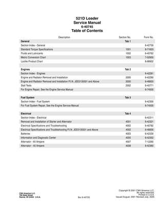
  • 1. Copyright © 2001 CNH America LLC. All rights reserved. Printed in U.S.A. Issued August, 2001 Revised July, 2005 CNH America LLC. 700 State Street Racine, WI 53404 U.S.A. Bur 6-42725 521D Loader Service Manual 6-40745 Table of Contents Description Section No. Form No. General Tab 1 Section Index - General 6-42730 Standard Torque Specifications 1001 8-71603 Fluids and Lubricants 1002 6-40762 Metric Conversion Chart 1003 7-52950 Loctite Product Chart 8-98902 Engines Tab 2 Section Index - Engines 6-42281 Engine and Radiator Removal and Installation 2000 6-42290 Engine and Radiator Removal and Installation P.I.N. JEE0135501 and Above 2000 6-48920 Stall Tests 2002 6-40771 For Engine Repair, See the Engine Service Manual 6-74500 Fuel System Tab 3 Section Index - Fuel System 6-42300 For Fuel System Repair, See the Engine Service Manual 6-74500 Electrical Tab 4 Section Index - Electrical 6-42311 Removal and Installation of Starter and Alternator 4001 6-42321 Electrical Specifications and Troubleshooting 4002 6-40782 Electrical Specifications and Troubleshooting P.I.N. JEE0135501 and Above 4002 6-48930 Batteries 4003 6-42330 Information and Diagnostic Center 4005 6-42352 Alternator - 65 Ampere 4007 7-12260 Alternator - 45 Ampere 4008 6-42360
  • 2. Bur 6-42725 Revised 7-05 Printed in U.S.A. Steering Tab 5 Section Index - Steering 6-42370 Removal and Installation of Steering Components 5001 6-42380 Steering Specifications, Pressure Checks, and Troubleshooting 5002 6-40790 Steering Control Valve 5003 6-42390 Steering Priority Valve 5004 6-42400 Steering Cylinders 5005 6-42410 Center Pivot 5006 6-42420 Auxiliary Steering Motor and Pump 5008 6-42430 Power Train Tab 6 Section Index - Power Train 6-42442 Removal and Installation of Power Train Components 6001 6-42451 Transmission Specifications, Pressure Checks, and Troubleshooting 6002 6-40800 Transmission 6003 6-42460 Front and Rear Axle 6004 6-42470 Front and Rear Axle P.I.N. JEE0135501 and Above 6004 6-48970 Drive Shafts, Center Bearing, and Universal Joints 6005 6-42480 Wheels and Tires 6006 6-42490 Transmission Control Valve 6007 6-42500 Brakes Tab 7 Section Index - Brakes 6-42510 Removal and Installation of Brake Components 7001 6-42521 Hydraulic Brake Troubleshooting 7002 6-40811 Brake Accumulators 7004 6-42531 Parking Brake 7008 6-42540 NOTE: For parking brake and brake pedal adjustments, see Section 9001. Hydraulics Tab 8 Section Index - Hydraulics 6-42551 Removal and Installation of Hydraulic Components 8001 6-42562 Hydraulic Specifications, Troubleshooting, and Pressure Checks 8002 6-40822 Cleaning the Hydraulic System 8003 7-49640 Loader Control Vale 8005 6-42580 Cylinders 8006 6-42591 Coupler Solenoid Locking Valve 8007 6-42600 Pilot Pressure Accumulator and Ride Control Accumulator 8013 6-42621 Ride Control Valve 8014 6-44751 521D Loader Service Manual 6-40745 Table of Contents Description Section No. Form No.
  • 3. Copyright © 2001 CNH America LLC. All rights reserved. Printed in U.S.A. Issued August, 2001 Revised July, 2005 CNH America LLC. 700 State Street Racine, WI 53404 U.S.A. Bur 6-42725 NOTE: Case Corporation reserves the right to make improvements in design or changes in specifications at any time without incurring any obligation to install them on units previously sold. Mounted Equipment Tab 9 Section Index - Mounted Equipment 6-42640 Pedals and Levers 9001 6-40830 Air Conditioning Troubleshooting and System Checks For Systems with HFC-134a Refrigerant 9002 6-42650 Air Conditioner System Service 9003 6-42660 Removal and Installation of Air Conditioning Components For Systems with HFC-134a Refrigerant 9004 6-42671 Loader 9006 6-42691 ROPS Cab and ROPS Canopy 9007 6-42700 Cab Glass Installation 9010 6-42710 Electrical Schematic Foldouts and Hydraulic Schematic Foldout In Rear Pocket 6-40841 Electrical Schematic Foldouts and Hydraulic Schematic Foldout P.I.N JEE0135501 and Above In Rear Pocket 6-49280 521D Loader Service Manual 6-40745 Table of Contents Description Section No. Form No.
  • 4. CASE CORPORATION 700 State Street Racine, WI 53404 U.S.A. CASE CANADA CORPORATION 3350 South Service Road Hamilton, ON L7N 3M6 CANADA Bur 6-42730 Copyright © 2001 Case Corporation Printed in U.S.A. August, 2001 SECTION INDEX GENERAL Standard Torque Specifications. . . . . . . . . . . . . . . . . . . . . . . . . . . . . . . . . . . . . . . . . . . . . . . . . . . . . . . . . . . . . 1001 Fluids and Lubricants . . . . . . . . . . . . . . . . . . . . . . . . . . . . . . . . . . . . . . . . . . . . . . . . . . . . . . . . . . . . . . . . . . . . .1002 Metric Conversion Chart . . . . . . . . . . . . . . . . . . . . . . . . . . . . . . . . . . . . . . . . . . . . . . . . . . . . . . . . . . . . . . . . . . .1003 Loctite Product Chart Section Title Section Number
  • 5. 1001-3 Bur 8-71603 Revised 4-04 Printed in U.S.A. TORQUE SPECIFICATIONS - DECIMAL HARDWARE Use the torques in this chart when special torques are not given. These torques apply to fasteners with both UNC and UNF threads as received from suppliers dry, or when lubricated with engine oil. Not applicable if special graphities, Molydisulfide greases, or other extreme pressure lubricants are used. Grade 5 Bolts, Nuts, and Studs Size Pound- Inches Newton metres 1/4 inch 108 to 132 12 to 15 5/16 inch 204 to 252 23 to 28 3/8 inch 420 to 504 48 to 57 Size Pound- Feet Newton metres 7/16 inch 54 to 64 73 to 87 1/2 inch 80 to 96 109 to 130 9/16 inch 110 to 132 149 to 179 5/8 inch 150 to 180 203 to 244 3/4 inch 270 to 324 366 to 439 7/8 inch 400 to 480 542 to 651 1.0 inch 580 to 696 787 to 944 1-1/8 inch 800 to 880 1085 to 1193 1-1/4 inch 1120 to 1240 1519 to 1681 1-3/8 inch 1460 to 1680 1980 to 2278 1-1/2 inch 1940 to 2200 2631 to 2983 Grade 8 Bolts, Nuts, and Studs Size Pound- Inches Newton metres 1/4 inch 144 to 180 16 to 20 5/16 inch 288 to 348 33 to 39 3/8 inch 540 to 648 61 to 73 Size Pound- Feet Newton metres 7/16 inch 70 to 84 95 to 114 1/2 inch 110 to 132 149 to 179 9/16 inch 160 to 192 217 to 260 5/8 inch 220 to 264 298 to 358 3/4 inch 380 to 456 515 to 618 7/8 inch 600 to 720 814 to 976 1.0 inch 900 to 1080 1220 to 1465 1-1/8 inch 1280 to 1440 1736 to 1953 1-1/4 inch 1820 to 2000 2468 to 2712 1-3/8 inch 2380 to 2720 3227 to 3688 1-1/2 inch 3160 to 3560 4285 to 4827 NOTE: Use thick nuts with Grade 8 bolts.
  • 6. 1001-4 Bur 8-71603 Revised 4-04 Printed in U.S.A. TORQUE SPECIFICATIONS - METRIC HARDWARE Use the following torques when specifications are not given. These values apply to fasteners with coarse threads as received from supplier, plated or unplated, or when lubricated with engine oil. These values do not apply if graphite or Molydisulfide grease or oil is used. Grade 12.9 Bolts, Nuts, and Studs Usually the torque values specified for grade 10.9 fasteners can be used satisfactorily on grade 12.9 fasteners. Grade 8.8 Bolts, Nuts, and Studs Size Pound- Inches Newton metres M4 24 to 36 3 to 4 M5 60 to 72 7 to 8 M6 96 to 108 11 to 12 M8 228 to 276 26 to 31 M10 456 to 540 52 to 61 Size Pound- Feet Newton metres M12 66 to 79 90 to 107 M14 106 to 127 144 to 172 M16 160 to 200 217 to 271 M20 320 to 380 434 to 515 M24 500 to 600 675 to 815 M30 920 to 1100 1250 to 1500 M36 1600 to 1950 2175 to 2600 8.8 Grade 10.9 Bolts, Nuts, and Studs Size Pound- Inches Newton metres M4 36 to 48 4 to 5 M5 84 to 96 9 to 11 M6 132 to 156 15 to 18 M8 324 to 384 37 to 43 Size Pound- Feet Newton metres M10 54 to 64 73 to 87 M12 93 to 112 125 to 150 M14 149 to 179 200 to 245 M16 230 to 280 310 to 380 M20 450 to 540 610 to 730 M24 780 to 940 1050 to 1275 M30 1470 to 1770 2000 to 2400 M36 2580 to 3090 3500 to 4200 10.9 12.9
  • 7. 1001-5 Bur 8-71603 Revised 4-04 Printed in U.S.A. TORQUE SPECIFICATIONS - STEEL HYDRAULIC FITTINGS Tube OD Hose ID Thread Size Pound- Inches Newton metres 37 Degree Flare Fitting 1/4 inch 6.4 mm 7/16-20 72 to 144 8 to 16 5/16 inch 7.9 mm 1/2-20 96 to 192 11 to 22 3/8 inch 9.5 mm 9/16-18 120 to 300 14 to 34 1/2 inch 12.7 mm 3/4-16 180 to 504 20 to 57 5/8 inch 15.9 mm 7/8-14 300 to 696 34 to 79 Tube OD Hose ID Thread Size Pound- Feet Newton metres 3/4 inch 19.0 mm 1-1/16-12 40 to 80 54 to 108 7/8 inch 22.2 mm 1-3/16-12 60 to 100 81 to 135 1.0 inch 25.4 mm 1-5/16-12 75 to 117 102 to 158 1-1/4 inch 31.8 mm 1-5/8-12 125 to 165 169 to 223 1-1/2 inch 38.1 mm 1-7/8-12 210 to 250 285 to 338 Split Flange Mounting Bolts Size Pound- Inches Newton metres 5/16-18 180 to 240 20 to 27 3/8-16 240 to 300 27 to 34 7/16-14 420 to 540 47 to 61 Size Pound- Feet Newton metres 1/2-13 55 to 65 74 to 88 5/8-11 140 to 150 190 to 203 Tube OD Hose ID Thread Size Pound- Inches Newton metres Straight Threads with O-ring 1/4 inch 6.4 mm 7/16-20 144 to 228 16 to 26 5/16 inch 7.9 mm 1/2-20 192 to 300 22 to 34 3/8 inch 9.5 mm 9/16-18 300 to 480 34 to 54 1/2 inch 12.7 mm 3/4-16 540 to 804 57 to 91 Tube OD Hose ID Thread Size Pound- Feet Newton metres 5/8 inch 15.9 mm 7/8-14 58 to 92 79 to 124 3/4 inch 19.0 mm 1-1/16-12 80 to 128 108 to 174 7/8 inch 22.2 mm 1-3/16-12 100 to 160 136 to 216 1.0 inch 25.4 mm 1-5/16-12 117 to 187 159 to 253 1-1/4 inch 31.8 mm 1-5/8-12 165 to 264 224 to 357 1-1/2 inch 38.1 mm 1-7/8-12 250 to 400 339 to 542
  • 8. Section 2000 2000 CASE CORPORATION 700 State Street Racine, WI 53404 U.S.A. CASE CANADA CORPORATION 3350 South Service Road Burlington, ON L7N 3M6 CANADA Bur 6-42290 Copyright © 2001 Case Corporation Printed in U.S.A. August,2001 ENGINE AND RADIATOR REMOVAL AND INSTALLATION
  • 9. 2000-3 Bur 6-42290 Issued 8-01 Printed in U.S.A. ENGINE Removal STEP 1 Park machine on a level surface and lower bucket to floor. Stop engine. Actuate brake pedal several times to discharge brake accumulators. Put key switch in ON position and move loader control lever back and forth at least 30 times to release any pressure from hydraulic circuit. Put key switch in OFF position. STEP 2 BD00M030 Put articulation lock in LOCKED position. STEP 3 Slowly loosen the filler cap for hydraulic reservoir to release air pressure in hydraulic reservoir. STEP 4 BD01D139 Open and raise hood. Put master disconnect switch in OFF position. STEP 5 BD01D141 Using a flat blade screwdriver or other suitable tool, disengage bottom clip (1) from hood prop (2) and pull bottom of prop from stud (3). Repeat to remove top of prop from hood; remove prop then close hood. STEP 6 BD01D142 Open screen. STEP 7 BD01D143 Remove cotter pin and three washers. 3 2 1
  • 10. 2000-4 Bur 6-42290 Issued 8-01 Printed in U.S.A. STEP 8 BD01D144 Remove four bolts (4) securing hinges of screen to hood. Disconnect prop bar (5) from screen and remove screen. STEP 9 BD01D255 Connect a lifting strap to the hood handle and connect lifting equipment to strap. Depress handle latch and let hood raise. STEP 10 BD01D256 Take up all slack in strap connected to hood handle. STEP 11 BD01D145 Remove lock nut (6) securing LH spring (7) to hood. Repeat to remove lock nut securing RH spring to hood. Disconnect springs from hood; it may be necessary to raise hood to disconnect springs from hood. STEP 12 BD01D258 At front RH side of hood, identify, tag, and disconnect hood wiring harness connector from rear chassis wiring harness connector. STEP 13 Lower hood. 4 4 5 7 6
  • 11. 2000-5 Bur 6-42290 Issued 8-01 Printed in U.S.A. STEP 14 BD01D149 Install two lifting eyes and connect lifting strap to eyes. STEP 15 BD01D254 Connect lifting equipment to the lifting straps. STEP 16 BD01D147 Remove two nuts and bolts and four washers securing hood. STEP 17 BD01D254 Carefully raise and remove hood from loader. Lower hood onto suitable platform and disconnect lifting equipment. STEP 18 BD01D150 Tag and disconnect engine wiring harness connector from air filter restriction switch. STEP 19 BD01D152 Loosen clamp on air cleaner intake hose and remove hose.
  • 12. 2000-6 Bur 6-42290 Issued 8-01 Printed in U.S.A. STEP 20 BD01D154 Loosen clamp on turbocharger intake hose and disconnect hose from turbocharger. STEP 21 BD01D155 Remove bolt and washer securing front of battery cover. STEP 22 BD01D156 Loosen bolt. Slide battery cover forward and remove. Repeat Steps 21 and 22 to remove RH battery cover. STEP 23 BD01D158 Disconnect battery cable from LH battery negative post. Put a plastic cap over the negative post. STEP 24 BD01D161 Disconnect battery cable from RH battery positive post. Put a plastic cap over the positive post. STEP 25 BD01D162 Support air cleaner assembly (9) and remove two lock nuts, washers, bolts (8), and washers. Remove air cleaner and support as an assembly. 8 9
  • 13. 2000-7 Bur 6-42290 Issued 8-01 Printed in U.S.A. STEP 26 BD01D165 Remove four bolts (10) and washers securing drive belt guard (11) to master disconnect switch mounting bracket and belt guard bracket. STEP 27 BD01D168 Remove clamp securing elbow to muffler. STEP 28 BD01D166 At front of engine, remove two bolts (12) and washers securing wiring harness clamps and muffler mounting bracket (13). STEP 29 BD01D167 Support muffler and brackets and remove three bolts and washers at rear of engine. Remove muffler and brackets as an assembly from engine. STEP 30 BD01D169 Loosen clamp and remove tube from turbocharger. STEP 31 BD01D170 Loosen two clamps. Remove tube and hose as an assembly. 10 11 12 12 13
  • 14. 2000-8 Bur 6-42290 Issued 8-01 Printed in U.S.A. STEP 32 BD01D172 Loosen two clamps. Remove tube and hose as an assembly. STEP 33 BD01D177 Cut, remove, and discard tie strap securing LH rear combination lamp wire. Identify, tag, and disconnect rear chassis wiring harness connector from combination lamp connector. Repeat this step for RH rear combination lamp. STEP 34 BD01D179 Connect lifting equipment to rear counterweight. Take up all slack in lifting equipment. STEP 35 BD01D178 Remove two nuts (14) and washers and two bolts (15), washers, and nuts. Remove counterweight (16) from loader and place on pallet. STEP 36 BD01D164 Identify, tag, and disconnect the four connectors. STEP 37 BD01D173 Pull rubber boot (17) back from starter B+ terminal (18). Remove the nut, lock washer, and flat washer from B+ terminal. Identify, tag, and disconnect the wires from terminal. 14 14 15 15 16 17 18
  • 15. 2000-9 Bur 6-42290 Issued 8-01 Printed in U.S.A. STEP 38 BD01D250 Identify and tag wire connected to starter solenoid terminal. Pull the plastic cap from starter solenoid terminal. Using a Phillips screwdriver, loosen terminal screw and disconnect wire from terminal. STEP 39 BD01D174 Remove nut (19) and washer. Disconnect ground cables from engine ground stud. Move ground cables away from engine. Remove bolt (20), lock washer, and washer securing harness clamps to engine. Top harness (21) is rear chassis wiring harness; bottom harness (22) is engine wiring harness. STEP 40 BD01D175 Remove nut and washer from engine ground stud. Disconnect the five ground wires of the rear chassis wiring harness from the stud. STEP 41 BD01D176 BD01D257 Route rear chassis wiring harness to front of engine. Cut, remove, and discard two tie straps then route harness to RH side of engine compartment and away from engine. 21 20 19 22
  • 16. 2000-10 Bur 6-42290 Issued 8-01 Printed in U.S.A. STEP 42 BD00M031 Put a 37.8 liter (10 gallon) container below radiator drain. Remove cap and drain coolant into container. Install cap after coolant has drained. STEP 43 BD01D184 Loosen two hose clamps. Remove bottom hose. STEP 44 BD01D185 Loosen two hose clamps. Remove upper hose. STEP 45 BD01D188 At top of cooling system frame, loosen two hose clamps (23). Remove hose (24). Remove two nuts (25) securing U-bolt (26). Remove U-bolt, clamp, and spacer. STEP 46 BD01D192 Remove two nuts securing U-bolt holding top coolant pipe. Remove U-bolt, clamp, and spacer. Remove top coolant pipe from cooling system frame. STEP 47 BD01D189 Put a 12.7 mm (1/2 inch) drive breaker bar or ratchet in bracket for automatic belt tensioner. Lift up on breaker bar or ratchet to release drive belt tension and remove belt. 23 23 24 26 25
  • 17. 2000-11 Bur 6-42290 Issued 8-01 Printed in U.S.A. STEP 48 BD01D180 If loader is equipped with air conditioning, identify, tag, and disconnect the engine wiring harness connectors from air compressor clutch connector (27) and high pressure switch connector (28). Disconnect engine wiring harness connector from disconnect switch wiring harness connector (29). STEP 49 BD01D193 Support air conditioning compressor and remove four bolts. STEP 50 BD01D218 Install battery cover. Put air conditioning compressor on battery cover. STEP 51 BD00M031 Put a 18.9 liter (5 gallon) container below engine oil drain. Remove cap and drain engine oil into container. Install cap after oil has drained. STEP 52 BD01D194 Disconnect hose from fitting installed in engine oil pan. Install a plug in hose and a cap on fitting. STEP 53 BD01D200 At front of engine, remove six bolts (30) securing drive shaft (31) to engine coupling. Use a pry bar to move drive shaft away from engine coupling. 27 28 29 30 31
  • 18. 2000-12 Bur 6-42290 Issued 8-01 Printed in U.S.A. STEP 54 BD01D208 Disconnect engine wiring harness connector (32) from transmission wiring harness bulkhead connector. Remove clamp (33) securing fuel supply hose to engine flywheel housing. Remove two clamps (34) securing fuel return hose to engine. STEP 55 BD01D209 If equipped, disconnect ether start nozzle from intake manifold. STEP 56 BD01D210 Cut, remove, and discard tie strap (35) securing ether start tube (36). Move ether start tube away from engine. Loosen clamp (37). Tag and disconnect fuel supply hose (38) from primer pump. Plug hose and cap fitting to prevent intrusion of foreign matter into fuel system. STEP 57 BD01D212 Remove nut and washer securing ball joint (39) to throttle lever (40). Remove two socket head bolts (41) and washers securing throttle bracket (42) to engine. Move throttle bracket with throttle cable and ball joint attached away from engine. 32 33 34 35 38 37 36 40 42 41 39
  • 19. 2000-13 Bur 6-42290 Issued 8-01 Printed in U.S.A. STEP 58 BD01D215 Connect a vacuum pump to hydraulic reservoir. If a vacuum pump is not available, drain the hydraulic oil (hydraulic reservoir holds 68.5 liters (18 gallons) of oil). Turn on vacuum pump (if available). Tag, disconnect, and plug hoses connected to brake pump. Plug hoses securely and cap fittings. Turn off vacuum pump. Remove clamp securing fuel return hose to engine. STEP 59 BD01D216 Tag and disconnect fuel return hose. Plug hose and cap fitting. STEP 60 BD01D217 Remove nut (43), washer, and bolt securing clamp (44) and engine oil pressure sender (45) to rear chassis. Remove these parts as an assembly and secure to engine using suitable means. STEP 61 BD01D219 Remove two nuts and remove belt guard bracket. STEP 62 BD01D203 If equipped, disconnect ether start solenoid connector from engine wiring harness connector. 44 45 43
  • 20. 2000-14 Bur 6-42290 Issued 8-01 Printed in U.S.A. STEP 63 BD01D220 Connect lifting equipment to engine lifting brackets. Take up all slack in lifting equipment. STEP 64 BD01D206 At front of engine, remove nut, bolt, and two washers securing both sides of engine to rear chassis. STEP 65 BD01D181 At rear of rear chassis, between fuel tank mounting plate and rear chassis, remove bolt and washer securing rear of engine to rear chassis. STEP 66 Slowly raise engine from rear chassis. Be sure all harness connections and hoses have been disconnected and out of the way. Remove engine from machine.
  • 21. 2000-15 Bur 6-42290 Issued 8-01 Printed in U.S.A. Installation STEP 67 BC01D128 If engine front rubber isolators require replacement, remove and discard isolators (51 and 53). Install new rubber isolator (53), washer (52), then rubber isolator (51). STEP 68 BC01D129 If engine rear rubber isolators require replacement, remove and discard isolators (46 and 48) and spacer (47). Install new rubber isolators (46 and 48) and spacer (47) in rear chassis. STEP 69 Slowly raise engine and move into position over rear chassis. Be sure all harness connections and hoses are out of the way then lower engine. Put washer (54) between front rubber isolator (53) and rear chassis. Install washer (55), bolt (56), washer (57), and nut (58) in engine front isolators. Lower engine into position. Install washer (49) and bolt (50) in rear isolator. STEP 70 BD01D206 At front of engine, tighten two bolts (56) to a torque of 244 to 298 Nm (180 to 220 lb-ft). 51. RUBBER ISOLATOR 56. BOLT 52. WASHER 57. WASHER 53. RUBBER ISOLATOR 58. NUT 54. WASHER A. ENGINE 55. WASHER B. REAR CHASSIS 52 55 51 56 A 53 54 B 57 58 46. RUBBER ISOLATOR 50. BOLT 47. SPACER A. ENGINE 48. RUBBER ISOLATOR B. REAR CHASSIS 49. WASHER A B 48 47 46 49 50 56
  • 22. Thank you very much for your reading. Please Click Here. Then Get COMPLETE MANUAL. NO WAITING NOTE: If there is no response to click on the link above, please download the PDF document first and then click on it.
  • 23. 2000-16 Bur 6-42290 Issued 8-01 Printed in U.S.A. STEP 71 BD01D181 At rear of rear chassis, between fuel tank mounting plate and rear chassis, tighten bolt (50) to a torque of 244 to 298 Nm (180 to 220 lb-ft). STEP 72 BD01D220 Disconnect lifting equipment from engine lifting brackets. STEP 73 BD01D203 At right side of engine compartment, connect ether start solenoid connector to engine wiring harness connector if equipped. STEP 74 BD01D219 Position belt guard bracket on rear chassis and secure using two nuts. STEP 75 BD01D217 Position engine oil pressure sender (45) and clamp (44) on tab of rear chassis. Install nut (43), washer, and bolt to secure clamp and engine oil pressure sender to rear chassis. STEP 76 BD01D216 Remove plug from hose and cap from fuel injection pump fitting. Connect fuel return hose to fuel injection pump following tag installed during removal. Position and tighten clamp. Remove and discard tag. 50 44 45 43
  • 24. 2000-17 Bur 6-42290 Issued 8-01 Printed in U.S.A. STEP 77 BD01D215 Install clamp to secure fuel return hose to engine. Turn on vacuum pump connected to hydraulic reservoir. Remove caps from fittings and plugs from hoses. Connect hoses to brake pump following tags installed during removal. Remove and discard tags. Turn off and disconnect vacuum pump from hydraulic reservoir. STEP 78 BD01D212 Position throttle bracket with throttle cable and ball joint attached on engine. Install two washers and socket head bolts (41) to secure throttle bracket (42) to engine. Connect ball joint (39) to throttle lever (40) and secure with nut and washer. STEP 79 BD01D209 If equipped, connect ether start nozzle to intake manifold. STEP 80 BD01D210 Remove cap from fitting and plug from hose. Connect fuel supply hose (38) to primer pump following tag installed during removal. Position and tighten clamp (37). Remove and discard tag. Install a new tie strap (35) to secure ether start tube (36). STEP 81 BD01D208 Position fuel return hose and secure using two clamps (34). Position fuel supply hose and secure using clamp (33). Connect engine wiring harness connector (32) to transmission wiring harness bulkhead connector. 40 42 41 39 35 38 37 36 32 33 34
  • 25. 2000-18 Bur 6-42290 Issued 8-01 Printed in U.S.A. STEP 82 BD01D200 At front of engine, position drive shaft (31) on engine coupling. Install six bolts (30) to secure drive shaft (31) to engine coupling. Tighten the six bolts to a torque of 53 to 62 Nm (39 to 46 lb-ft). STEP 83 BD01D194 Remove plug from oil drain hose and cap from fitting installed in engine oil pan. Connect and tighten hose to fitting. STEP 84 BD01D193 If loader is equipped with air conditioning, position and support air conditioning compressor and install four bolts. STEP 85 BD01D180 Connect engine wiring harness connector to disconnect switch wiring harness connector (29). If loader is equipped with air conditioning, connect the engine wiring harness connectors to air compressor clutch connector (27) and high pressure switch connector (28) following tags installed during removal. Remove and discard tags. STEP 86 BD01D189 Route drive belt on pulleys then put a 12.7 mm (1/2 inch) drive breaker bar or ratchet in bracket for automatic belt tensioner. Lift up on breaker bar or ratchet and position drive belt then release belt tensioner to put tension on drive belt. 30 31 27 28 29
  • 26. 2000-19 Bur 6-42290 Issued 8-01 Printed in U.S.A. STEP 87 BD01D192 Insert top coolant pipe in cooling system frame. Install spacer, clamp, and U-bolt then install two nuts. Do not tighten nuts at this time. STEP 88 BD01D188 At top of cooling system frame, install spacer, clamp, and U-bolt (26) and secure using two nuts (25). Do not tighten nuts at this time. Install hose (24). Position clamps (23) and tighten clamps to a torque of 10.1 to 11.3 Nm (90 to 100 lb-inch). Tighten four nuts securing two U-bolts. STEP 89 BD01D185 Install upper hose. Position and tighten hose clamps. STEP 90 BD01D184 Install bottom hose. Position and tighten hose clamps. STEP 91 BD01D257 BD01D176 Route rear chassis wiring harness around front of engine to LH side of engine compartment. Install two new tie straps. 23 23 24 26 25
  • 27. 2000-20 Bur 6-42290 Issued 8-01 Printed in U.S.A. STEP 92 BD01D175 Connect the five ground wires of the rear chassis wiring harness to the stud. Install washer and nut to secure ground wires to engine ground stud. STEP 93 BD01D174 Install bolt (20), lock washer, and washer to secure harness clamps to engine. Top harness (21) is rear chassis wiring harness; bottom harness (22) is engine wiring harness. Connect ground cables to engine ground stud. Install washer and nut (19) to secure ground cables. STEP 94 BD01D250 Connect wire to starter solenoid terminal following tag installed during removal. Using a Phillips screwdriver, tighten terminal screw. Install plastic cap in terminal screw recess. Remove and discard tag. STEP 95 BD01D173 Connect wires to starter B+ terminal (18) following tags installed during removal. Install flat washer, lock washer, and nut to secure wires. Position rubber boot (17) over starter B+ terminal. Remove and discard tags from wires. STEP 96 BD01D164 Connect connectors following tags installed during removal. Remove and discard tags. 21 20 19 22 17 18
  • 28. 2000-21 Bur 6-42290 Issued 8-01 Printed in U.S.A. STEP 97 BD01D179 BD01D178 Move counterweight into position at rear of loader. Install two nuts (14) and washers and two bolts (15), washers, and nuts. Tighten nuts to a torque of 693 to 780 Nm (510 to 575 lb-ft). Tighten bolts to a torque of 955 to 1075 Nm (704 to 793 lb-ft). STEP 98 BD01D177 Connect rear chassis wiring harness connector to combination lamp connector following tag installed during removal. Install new tie strap to secure LH rear combination lamp wire. Remove and discard tags. Repeat this step for RH rear combination lamp. STEP 99 BD01D172 Install tube and hose as shown. Position clamps and tighten to a torque of 10.1 to 11.3 Nm (90 to 100 lb-inch). STEP 100 BD01D170 Install tube and hose as shown. Position clamps and tighten to a torque of 10.1 to 11.3 Nm (90 to 100 lb-inch). STEP 101 BD01D169 Position tube on turbocharger. Do not tighten clamp at this time. 14 14 15 15 16
  • 29. 2000-22 Bur 6-42290 Issued 8-01 Printed in U.S.A. STEP 102 BD01D167 Install and support muffler and brackets on engine while connecting muffler to tube installed in Step 101. Install three washers and bolts at rear of engine finger tight. STEP 103 BD01D166 At front of engine, position wiring harness clamps on muffler mounting bracket (13). Secure clamps and muffler mounting bracket using two washers and bolts (12). Tighten bolts to a torque of 118 to 133 Nm (87 to 98 lb-ft). Tighten the three rear bolts installed in Step 102 to a torque of 34 to 39 Nm (25 to 28 lb-ft). STEP 104 BD01D168 Position clamp securing elbow to muffler. Tighten clamp to a torque of 20 to 25 Nm (15 to 18 lb-ft). Tighten clamp securing opposite end of elbow to turbocharger to a torque of 4.8 to 5.2 Nm (42.5 to 46 lb-inch). STEP 105 BD01D165 Position drive belt guard (11) and secure using four washers and bolts (10) to master disconnect switch mounting bracket and belt guard bracket. STEP 106 BD01D162 Position air cleaner assembly (9) and support as an assembly. Secure using two bolts (8), four washers, and two lock nuts. 12 12 13 10 11 8 9