
Recommended
Recommended
More Related Content
More from fujskekdjdmkm3e
More from fujskekdjdmkm3e (20)
Recently uploaded
Recently uploaded (20)
2008 Mazda Rx8 Service Repair Manual.pdf
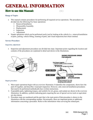
- 1. GENERAL INFORMATION How to use this Manual: (w) Range of Topics • This manual contains procedures for performing all required service operations. The procedures are divided into the following five basic operations: Removal/Installation Disassembly/Assembly Replacement Inspection Adjustment • Simple operations which can be performed easily just by looking at the vehicle (i.e., removal/installation of parts, jacking, vehicle lifting, cleaning of parts, and visual inspection) have been omitted. Service Procedure Inspection, adjustment • Inspection and adjustment procedures are divided into steps. Important points regarding the location and contents of the procedures are explained in detail and shown in the illustrations. Repair procedure 1. Most repair operations begin with an overview illustration. It identifies the components, shows how the parts fit together, and describes visual part inspection. However, only removal/installation procedures that need to be performed methodically have written instructions. 2. Expendable parts, tightening torques, and symbols for oil, grease, and sealant are shown in the overview illustration. In addition, symbols indicating parts requiring the use of special service tools or equivalent are also shown. 3. Procedure steps are numbered and the part that is the main point of that procedure is shown in the illustration with the corresponding number. Occasionally, there are important points or additional information concerning a procedure. Refer to this information when servicing the related part. (w) RX8-General Info Page 1
- 3. Symbols • There are eight symbols indicating oil, grease, fluids, sealant, and the use of SST or equivalent. These symbols show application points or use of these materials during service. Symbol Meaning Kind Apply oil New appropriate engine oil or gear oil Apply brake fluid New appropriate brake fluid Apply automatic transaxle/ transmission fluid New appropriate automatic transaxle/ transmission fluid Apply grease Appropriate grease Apply sealant Appropriate sealant Apply petroleum jelly Appropriate petroleum jelly Replace part O-ring, gasket, etc. Use SST or equivalent Appropriate tools (w) RX8-General Info Page 3
- 4. Advisory Messages • You will find several Warnings , Cautions , Notes , Specifications and Upper and Lower Limits in this manual. Warning • A Warning indicates a situation in which serious injury or death could result if the warning is ignored. Caution • A Caution indicates a situation in which damage to the vehicle or parts could result if the caution is ignored. Note • A Note provides added information that will help you to complete a particular procedure. Specification • The values indicate the allowable range when performing inspections or adjustments. Upper and lower limits • The values indicate the upper and lower limits that must not be exceeded when performing inspections or adjustments. (w) RX8-General Info Page 4 Notes:
- 5. Troubleshooting Procedure Basic flow of troubleshooting DTC troubleshooting flow (on-board diagnostic) • Diagnostic trouble codes (DTCs) are important hints for repairing malfunctions that are difficult to simulate. Perform the specific DTC diagnostic inspection to quickly and accurately diagnose the malfunction. • The on-board diagnostic function is used during inspection. When a DTC is shown specifying the cause of a malfunction, continue the diagnostic inspection according to the items indicated by the on-board diagnostic function. Diagnostic index • The diagnostic index lists the symptoms of specific malfunctions. Select the symptoms related or most closely relating to the malfunction. (w) RX8-General Info Page 5
- 6. Quick diagnosis chart (If mentioned) • The quick diagnosis chart lists diagnosis and inspection procedures to be performed specifically relating to the cause of the malfunction. Symptom troubleshooting • Symptom troubleshooting quickly determines the location of the malfunction according to symptom type. Procedures for Use Using the basic inspection (section 05) • Perform the basic inspection procedure before symptom troubleshooting. • Perform each step in the order shown. • The reference column lists the location of the detailed procedure for each basic inspection. • Although inspections and adjustments are performed according to the reference column procedures, if the cause of the malfunction is discovered during basic inspection, continue the procedures as indicated in the action column. (w) RX8-General Info Page 6
- 7. Using the DTC troubleshooting flow • DTC troubleshooting flow shows diagnostic procedures, inspection methods, and proper action to take for each DTC. (w) RX8-General Info Page 7
- 8. Using the diagnostic index • The symptoms of the malfunctions are listed in the diagnostic index for symptom troubleshooting. • The exact malfunction symptoms can be selected by following the index. (w) RX8-General Info Page 8 Notes:
- 9. Using the quick diagnosis chart • The chart lists the relation between the symptom and the cause of the malfunction. • The chart is effective in quickly narrowing down the relation between symptom and cause of the malfunction. It also specifies the area of the common cause when multiple malfunction symptoms occur. • The appropriate diagnostic inspection relating to malfunction cause as specified by the symptoms can be selected by looking down the diagnostic inspection column of the chart. Using the symptom troubleshooting • Symptom troubleshooting shows diagnostic procedures, inspection methods, and proper action to take for each trouble symptom. (w) RX8-General Info Page 9
- 10. (w) RX8-General Info Page 10
- 11. SERVICE CAUTIONS Protection of the Vehicle • Always be sure to cover fenders, seats and floor areas before starting work. Preparation of Tools and Measuring Equipment • Be sure that all necessary tools and measuring equipment are available before starting any work. Special Service Tools • Use special service tools or equivalent when they are required. Disconnection of the Negative Battery Cable • Before beginning any work, turn the ignition switch to LOCK position, then disconnect the negative battery cable and wait for more than 1 min. to allow the backup power supply of the SAS control module to deplete its stored power. Disconnecting the battery cable will delete the memories of the clock, audio, and DTCs, etc. Therefore, it is necessary to verify those memories before disconnecting the cable. (w) RX8-General Info Page 11
- 12. WARNING: • For vehicles with DSC, if the negative battery cable is disconnected, the stored initial position of the steering angle sensor will be cleared and the DSC will not operate properly, making the vehicle unsafe to drive. Perform the steering angle sensor initialization procedure after connecting the negative battery cable. (See STEERING ANGLE SENSOR INITIALIZATION PROCEDURE ) Oil Leakage Inspection • Use either of the following procedures to identify the type of oil that is leaking: Using UV light (black light) 1. Remove any oil on the engine or transmission. NOTE: • Referring to the fluorescent dye instruction manual, mix the specified amount of dye into the engine oil or ATF (or transmission oil). 2. Pour the fluorescent dye into the engine oil or ATF (or transmission oil). 3. Allow the engine to run for 30 min. 4. Inspect for dye leakage by irradiating with UV light (black light), and identify the type of oil that is leaking. 5. If no dye leakage is found, allow the engine to run for another 30 min. or drive the vehicle then reinspect. 6. Find where the oil is leaking from, then make necessary repairs. NOTE: • To determine whether it is necessary to replace the oil after adding the fluorescent dye, refer to the fluorescent dye instruction manual. Not using UV light (black light) 1. Gather some of the leaking oil using an absorbent white tissue. 2. Take samples of engine oil and ATF (or transmission oil), both from the dipstick, and place them next to the leaked oil already gathered on the tissue. 3. Compare the appearance and smell, and identify the type of oil that is leaking. 4. Remove any oil on the engine or transmission. 5. Allow the engine to run for 30 min. (w) RX8-General Info Page 12
- 13. 6. Check the area where the oil is leaking, then make necessary repairs. Removal of Parts • While correcting a problem, also try to determine its cause. Begin work only after first learning which parts and subassemblies must be removed and disassembled for replacement or repair. After removing the part, plug all holes and ports to prevent foreign material from entering. Disassembly • If the disassembly procedure is complex, requiring many parts to be disassembled, all parts should be marked in a place that will not affect their performance or external appearance and identified so that reassembly can be performed easily and efficiently. Inspection During Removal, Disassembly • When removed, each part should be carefully inspected for malfunction, deformation, damage and other problems. (w) RX8-General Info Page 13
- 14. Arrangement of Parts • All disassembled parts should be carefully arranged for reassembly. • Be sure to separate or otherwise identify the parts to be replaced from those that will be reused. Cleaning of Parts • All parts to be reused should be carefully and thoroughly cleaned in the appropriate method. WARNING: • Using compressed air can cause dirt and other particles to fly out causing injury to the eyes. Wear protective eye wear whenever using compressed air. Reassembly • Standard values, such as torques and certain adjustments, must be strictly observed in the reassembly of all parts. • If removed, the following parts should be replaced with new ones: Oil seals Gaskets O-rings Lock washers (w) RX8-General Info Page 14
- 15. Cotter pins Nylon nuts • Depending on location: Sealant and gaskets, or both, should be applied to specified locations. When sealant is applied, parts should be installed before sealant hardens to prevent leakage. Oil should be applied to the moving components of parts. Specified oil or grease should be applied at the prescribed locations (such as oil seals) before reassembly. Adjustment • Use suitable gauges and testers when making adjustments. Rubber Parts and Tubing • Prevent gasoline or oil from getting on rubber parts or tubing. (w) RX8-General Info Page 15
- 16. Hose Clamps • When reinstalling, position the hose clamp in the original location on the hose and squeeze the clamp lightly with large pliers to ensure a good fit. Torque Formulas • When using a torque wrench- SST or equivalent combination, the written torque must be recalculated due to the extra length that the SST or equivalent adds to the torque wrench. Recalculate the torque by using the following formulas. Choose the formula that applies to you. Torque Unit Formula N·m N·m × [L/(L+A)] kgf·m kgf·m × [L/(L+A)] kgf·cm kgf·cm × [L/(L+A)] ft·lbf ft·lbf × [L/(L+A)] in·lbf in·lbf × [L/(L+A)] A The length of the SST past the torque wrench drive. L The length of the torque wrench. (w) RX8-General Info Page 16
- 17. Vise • When using a vise, put protective plates in the jaws of the vise to prevent damage to parts. Dynamometer • When inspecting and servicing the power train on the dynamometer or speed meter tester, pay attention to the following: Place a fan, preferably a vehicle-speed proportional type, in front of the vehicle. Make sure the vehicle is in a facility with an exhaust gas ventilation system. Since the rear bumper might deform from the heat, cool the rear with a fan. (Surface of the bumper must be below 70° ° ° °C {158° ° ° °F} degrees .) Keep the area around the vehicle uncluttered so that heat does not build up. Watch the water temperature gauge and don't overheat the engine. Avoid added load to the engine and maintain normal driving conditions as much as possible. NOTE: • When only the front or rear wheels are rotated on a chassis dynamometer or equivalent, the ABS/DSC CM determines that there is a malfunction in the ABS/DSC and illuminates the following lights: Vehicles with ABS • ABS warning light • Brake system warning light Vehicles with DSC • ABS warning light • Brake system warning light • DSC indicator light • If the above lights are illuminated, dismount the vehicle from the chassis dynamometer and turn the ignition switch to the LOCK position. Then, turn the ignition switch back to the ON position, run the vehicle at 10 km/h or more and verify that the warning lights go out. In this case, a DTC will be stored in the memory. Clear the DTC from the memory by following the memory clearing procedure [ABS]/[DSC] in the on-board diagnostic system. (See ON-BOARD DIAGNOSIS [ABS] ) (See ON-BOARD DIAGNOSIS [DYNAMIC STABILITY CONTROL] ) (w) RX8-General Info Page 17
- 18. IDENTIFICATION NUMBER LOCATIONS Vehicle Identification Number (VIN) Chassis Number Engine Identification Number (w) RX8-General Info Page 18 VIN: Chassis: EIN: Notes:
- 19. Thank you very much for your reading. Please Click Here Then Get More Information.