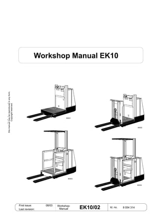
2. Issue: 08/03 Workshop-
ManualReplaces issue: EK10/02 Sheet no.
Copygpoeedopo
thismanualmaybereproducedinanyform.
Copyrightreserved.
4
1 Vehicle data
2 Travel motor
3 Drive wheel
4 Gear
5 Brake
6 Idling wheels
7 Hydraulic
8 Cylinder
9 Line break protection
10 Hydraulic pump
11 Aisle recognition
12 Steering
13 Vehicle control system (FZS)
14 Operating panel
15 End-of-aisle safety system (EASS)
16 Speed sensor
17 Braking monitor (ABÜ)
18 Travel control
19 Travel switch
20 BDI/HM
21 Travel control software
22 Steering software
23 Hand-held programming unit
99 Maintenance
Sections
3. Issue: 08/03 Workshop-
ManualReplaces issue: EK10/02 Sheet no.
Copygpoeedopo
thismanualmaybereproducedinanyform.
Copyrightreserved.
5
Section Contents Sheet
Foreword ......................................................................................2
Updating of workshop manuals............................................2
Exchanging faulty sheets .....................................................3
Insertion of supplementary sheets .......................................3
Remarks, imprint ..........................................................................4
Sections........................................................................................5
1 Vehicle data
Definition of vehicle model names...........................................1-01
Signs on the vehicle ................................................................1-02
Travel speed ...........................................................................1-03
Outside the aisle .............................................................1-03
Inside the aisle................................................................1-03
2 Travel motor
General....................................................................................2-01
Temperature monitor ...............................................................2-01
Technical data .........................................................................2-02
Terminals.................................................................................2-02
Removing the travel motor ......................................................2-03
Installation ...............................................................................2-04
Maintenance............................................................................2-05
General ...........................................................................2-05
Cleaning..........................................................................2-05
Visual inspection, replacing damaged parts ...................2-06
Checking the brush mechanism......................................2-08
Commutator ....................................................................2-09
Bearings..........................................................................2-09
3 Drive wheel
General....................................................................................3-01
Removing the drive wheel.......................................................3-01
Installing the drive wheel.........................................................3-01
4 Gear
Remove ...................................................................................4-01
Installing the gear....................................................................4-02
Changing oil ............................................................................4-03
Oil change method ..................................................................4-04
Checking the oil level ..............................................................4-05
Lubricating the bogie bearing..................................................4-05
Table of Contents
4. Issue: 08/03 Workshop-
ManualReplaces issue: EK10/02 Sheet no.
Copygpoeedopo
thismanualmaybereproducedinanyform.
Copyrightreserved.
6
Table of Contents
Section Contents Sheet
5 Brake
Electromagnetic spring brake ..................................................5-01
General ...........................................................................5-01
Function ..........................................................................5-02
Removal..........................................................................5-03
Checking the rotor...........................................................5-03
Adjusting the brake clearance.........................................5-04
General...................................................................5-04
Adjustment process................................................5-04
Adjusting the braking force..............................................5-05
Maintenance....................................................................5-06
Measuring the brake deceleration ...........................................5-07
General ...........................................................................5-07
Preparations for measurement........................................5-07
Evaluating the measurement ..........................................5-08
6 Idling wheels
General....................................................................................6-01
Removal ..................................................................................6-01
7 Hydraulic
Montagevorschrift ....................................................................7-01
Hydraulic circuit plan ...............................................................7-01
Block diagram for NO/HO........................................................7-02
Block diagram for NM/HM .......................................................7-03
Pump unit ................................................................................7-04
General ...........................................................................7-04
Components:...................................................................7-04
Electrically releasable non-return valve ..........................7-05
Replacing the carbon brushes (NO, NM)........................7-06
Replacing the carbon brushes (HO, HM)........................7-07
Removal..........................................................................7-08
Removing the pump motor (NO, NM) .............................7-09
Removing the pump motor (HO, HM) .............................7-10
Adjustment Pressure release valve.................................7-11
Changing the hydraulic oil...............................................7-12
Bleeding the lift cylinders and the hydraulic system................7-13
Procedure........................................................................7-13
Distributor block.......................................................................7-14
Bubble reservoir ......................................................................7-15
Hydraulic hoses .......................................................................7-16
5. Issue: 08/03 Workshop-
ManualReplaces issue: EK10/02 Sheet no.
Copygpoeedopo
thismanualmaybereproducedinanyform.
Copyrightreserved.
7
Table of Contents
Section Contents Sheet
8 Cylinders
Cylinder support ......................................................................8-01
Main lift cylinder on NO/NM.....................................................8-02
Removal .........................................................................8-02
Dismantling ....................................................................8-03
Main lift cylinder on HO/HM.....................................................8-04
Removal .........................................................................8-04
Dismantling ....................................................................8-05
Additional lift cylinder on NM/HM.............................................8-06
Removal .........................................................................8-06
Dismantling ....................................................................8-07
9 Line break protection
General....................................................................................9-01
10 Hydraulic pump
General..................................................................................10-01
Removing ..............................................................................10-02
Dismantling............................................................................10-03
11 Aisle recognition
General ..................................................................................11-01
12 Steering
Block diagram of the steering system....................................12-01
Pin assignment......................................................................12-02
Setpoint potentiometer, steering wheel .................................12-04
Replacing ......................................................................12-04
Setpoint potentiometer, steering knob...................................12-05
Replacing ......................................................................12-05
Actual value potentiometer....................................................12-06
Replacing ......................................................................12-06
Quick start .............................................................................12-07
Travel on curves function.......................................................12-08
Steering lock..........................................................................12-09
13 Vehicle control system (FZS)
General..................................................................................13-01
Location.................................................................................13-01
Identification ..........................................................................13-01
Technical data........................................................................13-01
Guide to versions...................................................................13-02
Pin assignment......................................................................13-03
Input/output assignment ........................................................13-06
6. Issue: 08/03 Workshop-
ManualReplaces issue: EK10/02 Sheet no.
Copygpoeedopo
thismanualmaybereproducedinanyform.
Copyrightreserved.
Table of Contents
Section Contents Sheet
13 Vehicle control system
Error diagnosis........................................................................13-07
Flashing code, FZS2......................................................13-07
Table of functions, FZS2.........................................................13-08
Application......................................................................13-08
Pedestrian operating mode ...........................................13-09
Switch-over, 2nd operating console ...............................13-10
Power outputs ................................................................13-11
Travel enable..................................................................13-12
14 Operating console
Position of the operating elements .........................................14-01
Removal..................................................................................14-01
Installing..................................................................................14-01
Wheel position display............................................................14-02
Adjustment .....................................................................14-02
Teaching in the FZS2 .....................................................14-02
2nd operating console ............................................................14-03
Pedestrian operating mode.....................................................14-04
15 End-of-aisle safety system (EASS)
End-of-aisle safety system (EASS).........................................15-01
General ..........................................................................15-01
EASS Universal ......................................................................15-02
Error codes.....................................................................15-03
EASS Inductive.......................................................................15-04
Function .........................................................................15-04
Guide to the system .......................................................15-06
Monitoring .....................................................................15-07
Mounting the proximity switches ....................................15-08
Testing the proximity switches........................................15-08
Displays and pin assignment ........................................15-09
EASS Magnetic (bistable).......................................................15-10
Function .........................................................................15-10
Guide to the system .......................................................15-12
Monitoring ......................................................................15-13
Magnetic switch..............................................................15-14
Description.............................................................15-14
Bistable action .......................................................15-14
Switching magnet...........................................................15-15
Description.............................................................15-15
Handling instructions .............................................15-15
Displays and pin assignment .......................................15-16
8
7. Issue: 08/03 Workshop-
ManualReplaces issue: EK10/02 Sheet no.
Copygpoeedopo
thismanualmaybereproducedinanyform.
Copyrightreserved.
Table of Contents
9
Section Contents Sheet
16 Speed sensor
General..................................................................................16-01
Terminals block connector X2 .......................................16-01
Signal sequence............................................................16-01
Testing the speed sensor.......................................................16-02
17 ABÜ - Braking monitor
Block diagram........................................................................17-01
Pin assignment......................................................................17-02
General..................................................................................17-04
Functions...............................................................................17-05
Travel on curves............................................................17-05
Signal adaptation..................................................17-05
Flashing error codes..............................................................17-06
18 Travel control
Block diagram for "Travel" .....................................................18-01
General..................................................................................18-02
Main current section - terminals ............................................18-03
Pin assignment......................................................................18-04
Description of functions .........................................................18-07
Braking modes ..............................................................18-07
Table of operating modes..............................................18-07
Hour meter ....................................................................18-08
Service hour meter........................................................18-08
Battery discharge indicator............................................18-08
Monitoring function........................................................18-09
Error display ..........................................................................18-10
Test procedure.......................................................................18-10
19 Direction sender
General..................................................................................19-01
Replacing...............................................................................19-01
20 BDI/HM
General..................................................................................20-01
Pin assignment......................................................................20-02
Function.................................................................................20-03
Error display ..........................................................................20-03
Battery discharge indicator....................................................20-03
Hour meter.............................................................................20-04
8. Issue: 08/03 Workshop-
ManualReplaces issue: EK10/02 Sheet no.
Copygpoeedopo
thismanualmaybereproducedinanyform.
Copyrightreserved.
Section Contents Sheet
21 Travel control software
General..................................................................................21-01
Making a connection..............................................................21-01
Setting parameters ................................................................21-02
Test........................................................................................21-03
Diagnosis...............................................................................21-03
"File" menu ............................................................................21-03
Summary of the most important parameters .........................21-05
Battery discharge curves.......................................................21-06
List of parameters..................................................................21-07
Description of parameters .....................................................21-12
Errors displayed with flashing code.......................................21-17
List of error codes..................................................................21-18
Tester Table ...........................................................................21-19
22 Steering software
General..................................................................................22-01
Making a connection..............................................................22-02
Errors.....................................................................................22-03
Current errors................................................................22-03
Stored errors .................................................................22-03
Teaching in ............................................................................22-04
General .........................................................................22-04
Procedure......................................................................22-04
Setpoint potentiometer..................................................22-05
Actual value potentiometer............................................22-06
Tester.....................................................................................22-09
Speed measurement.....................................................22-09
Amplifier data ................................................................22-10
Digital inputs and outputs..............................................22-11
Travel on curves active .........................................22-11
Deadman ..............................................................22-11
Steering wheel/ -knob ...........................................22-11
Steering OK ..........................................................22-11
Steering motor contactor ......................................22-12
Safety relay...........................................................22-12
Potentiometer voltages .................................................22-13
Supply voltage of actual and setpoint values .......22-13
Setpoint voltage at the steering wheel..................22-13
Actual value voltages at the drive wheel ..............22-13
Table of errors........................................................................22-14
10
Table of Contents
9. Issue: 08/03 Workshop-
ManualReplaces issue: EK10/02 Sheet no.
Copygpoeedopo
thismanualmaybereproducedinanyform.
Copyrightreserved.
Section Contents Sheet
23 Hand-held programming unit
General..................................................................................23-01
Operating elements...............................................................23-01
Switching on ..........................................................................23-02
Switching off ..........................................................................23-02
Language selection ...............................................................23-03
Setting parameters ................................................................23-04
PROGRAM menu .........................................................23-04
Function ........................................................................23-05
Special program menu ..........................................................23-06
Resetting to initial settings ............................................23-07
Loading settings from the control system
into the programming unit .............................................23-08
Loading settings from the programming unit
into the control system..................................................23-09
Deleting the diagnosis data...........................................23-10
Adjusting the display contrast .......................................23-11
Language selection.......................................................23-12
Displaying information about the programming unit......23-12
Displaying information about the control.......................23-12
Test menu..............................................................................23-13
Displaying current errors .......................................................23-14
Error history...........................................................................23-14
11
Table of Contents
10. Issue: 08/03 Workshop-
ManualReplaces issue: EK10/02 Sheet no.
Copygpoeedopo
thismanualmaybereproducedinanyform.
Copyrightreserved.
Section Contents Sheet
99 Maintenance
General...................................................................................99-01
Safety instructions ..................................................................99-02
Handling fuels and lubricants.........................................99-02
Brake ......................................................................................99-03
Functional check of the deadman brake ........................99-03
Functional check of the neutral brake ............................99-03
Functional check of the reversing brake ........................99-03
Maximum wear on the brake lining ................................99-03
Brake clearance .............................................................99-03
Battery ....................................................................................99-04
Checking the electrolyte level ........................................99-04
Checking the electrolyte density ....................................99-04
Cleaning the battery.......................................................99-04
Battery lock ....................................................................99-05
Battery charger...............................................................99-05
Operating elements ................................................................99-06
Ease of movement .........................................................99-06
Function test...................................................................99-06
Steering ..................................................................................99-07
Ease of movement .........................................................99-07
Reversed steering..........................................................99-07
Steering angle................................................................99-07
Switching-off in the event of error ..................................99-07
Toothed gear ring ...........................................................99-07
Lifting chains...........................................................................99-08
General ..........................................................................99-08
Checking the lifting chains for damage ..........................99-09
Checking the chain elongation.......................................99-13
Main lift ..................................................................99-13
Checking the chain elongation.......................................99-14
Additional lift ..........................................................99-14
Replacing the lifting chains ............................................99-15
Repairing the lifting chains.............................................99-15
Lubricating the lifting chains...........................................99-16
Cleaning the chains........................................................99-17
Hydraulic tank.........................................................................99-18
Volume ...........................................................................99-18
Seals ..............................................................................99-18
12
Table of Contents
12. 07/01 01
Chapter 1 Vehicle data
Copygpoeedopo
thismanualmaybereproducedinanyform.
Copyrightreserved.
Issue: 08/03 Workshop-
ManualReplaces issue: EK10/02 Sheet no. 1 – 01
EK10 HM (Hochhub mit Zusatzhub)
= high lift with additional lift)
EK10 HO (Hochhub ohne Zusatzhub
= high lift without additional lift)
EK10 NM (Niederhub mit Zusatzhub
= low lift with additional lift)
EK10 NO (Niederhub ohne Zusatzhub
= low lift without additional lift)
Definition of vehicle model names
80001
80004
80003
80002
13. Chapter 1 Vehicle data
Copygpoeedopo
thismanualmaybereproducedinanyform.
Copyrightreserved.
Issue: 08/03 Workshop-
ManualReplaces issue: EK10/02 Sheet no. 1 – 02
Signs on the vehicle
Nameplate
UVV check
Carrying load diagram
Vehicle no. on chassis
30115
30116
30117
30118
30119
14. Chapter 1 Vehicle data
Copygpoeedopo
thismanualmaybereproducedinanyform.
Copyrightreserved.
Issue: 08/03 Workshop-
ManualReplaces issue: EK10/02 Sheet no. 1 – 03
Travel speed
Outside the aisle
• Type NO always vmax = 9.0km/h
• Type NM Platform level < 0.5m vmax = 9.0km/h
• Type NM Platform level > 0.5m & steering straight-on vmax = 4.0km/h
• Type NM Platform level > 0.5m & steering > ±10° vmax = 2.5km/h
• Type HO Platform level < 1.2m vmax = 9.0km/h
• Type HO Platform level > 1.2m & steering straight-on vmax = 4.0km/h
• Type HO Platform level > 1.2m & steering > ±10° vmax = 2.5km/h
• Type HM Platform level < 0.5m vmax = 9.0km/h
• Type HM Platform level > 0.5m & steering straight-on vmax = 4.0km/h
• Type HM Platform level > 0.5m & steering > ±10° vmax = 2.5km/h
Inside the aisle
Always vmax = 9,0km/h
15. Chapter 2 Travel motor
Copygpoeedopo
thismanualmaybereproducedinanyform.
Copyrightreserved.
Issue: 08/03 Workshop-
ManualReplaces issue: EK10/02 Sheet no. 2–
General
The drive motor used in this vehicle is a 24V shunt
motor.
The armature and field coils are controlled separately
by the travel controller.
The travel movement is initiated as follows: voltage is
applied to the armature and the field is excited.
As soon as the armature voltage is equal to the
battery voltage, the field current is reduced in order to
achieve an increase in speed.
The current speed of the drive motor is determined by
a current measurement (measuring shunt) in the
travel controller.
Temperature monitor
The drive motor has a temperature monitor (field coil
resistor at normal temperature approx. 1.8 ).
If the temperature is >90°C, deceleration is initiated
by the MOT WRM parameter. If the temperature rises
above 105°C, a traction cut-out is initiated by the Mot
Hot parameter (see Software travel controle).
01
30122
16. Thank you very much for
your reading. Please Click
Here. Then Get COMPLETE
MANUAL. NO WAITING
NOTE:
If there is no response to
click on the link above,
please download the PDF
document first and then
click on it.
17. Chapter 2 Travel motor
Copygpoeedopo
thismanualmaybereproducedinanyform.
Copyrightreserved.
Issue: 08/03 Workshop-
ManualReplaces issue: EK10/02 Sheet no. 2–
Technical data
Model designation GF 114 - F4
Id. no. W8 408 250
Excitation type shunt wound
Voltage 24V
Rated output 2000W
Rated speed 2700 rpm
Direction of rotation right / left
Protection / insulation class JP 00 / 20
Field excitation 6V / 9A
Armature current 104A
On-period S2 = 60min
Terminals
A 1 Armature winding start
A 2 Armature winding end
F1 Field winding
F2 Field winding
02
Right rot.
Left rot.
A1 A2 F1 F2
+ - -+
A1 A2 F1 F2
+ - +-
M
M
30120
2
3 4
1
18. Chapter 2 Travel motor
Copygpoeedopo
thismanualmaybereproducedinanyform.
Copyrightreserved.
Issue: 08/03 Workshop-
ManualReplaces issue: EK10/02 Sheet no. 2– 03
Removing the travel motor
Because the brake (2) is mounted on the
travel motor, the vehicle is no longer
braked once the brake and the travel
motor have been removed. For this
reason, always secure the vehicle to
prevent it rolling away!
• Pull out the battery plug.
• Remove power leads (3.
• Unplug speed sensor (9).
• Remove electro magnetic break (2)
The connection point for the connection
cable of the spring brake may be in the
cable duct (4)!
• Remove the 8 screws (5).
• Screw the special eyebolt tool M6 (6), into the
armature shaft (min. 20mm).
• Pull the rope (7) (special tool: pulley) through the
eyebolt (6).
Ensure that the rope is pulled through
correctly (8).
• Set the length (holding it tight with your hand is
sufficient).
• Lift the travel motor out with a lever rod.
Never work without the correct aids. A
considerable amount of force is required
to release the seal (1) between the travel
motor and the gear.
• Remove the aids.
• Lift the travel motor out by hand.
When the travel motor has been removed,
the opening left in the gear (2) must be
closed off immediately, in order to prevent
oil entering the inside of the gear.
2
3
5
3
9
4
60222
7
8
6
62005
62004
00178
48
41.5
min. 20mm
M6x60
19. Chapter 2 Travel motor
Copygpoeedopo
thismanualmaybereproducedinanyform.
Copyrightreserved.
Issue: 08/03 Workshop-
ManualReplaces issue: EK10/02 Sheet no. 2– 04
Installation
To install the travel motor, follow the instructions for
removal in reverse order.
It can be installed without the use of any special
tools.
Only use screws of the prescribed
length, otherwise the four-point
bearing may be damaged!
Screw in and tighten the 8 screws (3)
diagonally in several passes. 3
MA = 23Nm us
Loctite
MA = 26Nm
MA = 140Nm
1
2
62006