SlideShare a Scribd company logo
1 of 21
Download to read offline
2005 STEERING
Steering Wheel and Column - XLR
SPECIFICATIONS
FASTENER TIGHTENING SPECIFICATIONS
Fastener Tightening Specifications
SCHEMATIC AND ROUTING DIAGRAMS
COLUMN/IGNITION LOCK SCHEMATICS
Application
Specification
Metric English
Column Support Bracket Nuts 24 N.m 17 lb ft
Dampener Screws 1.5 N.m 13 lb in
Intermediate Shaft to the Steering Column Pinch Bolt 48 N.m 35 lb ft
Intermediate Shaft to the Steering Gear Pinch Bolt 34 N.m 25 lb ft
Intermediate Shaft to the Steering Gear Pinch Bolt Shield
Screw
3.5 N.m 31 lb in
Steering Column Bottom Bracket Screw 3 N.m 27 lb in
Steering Column Support Screws 17 N.m 13 lb ft
Steering Column Trim Cover Screws Lower 3 N.m 27 lb in
Steering Column Trim Cover Screw Upper 1.5 N.m 13 lb in
Steering Wheel Control Harness Retainer And Screw 2.3 N.m 20 lb in
Steering Wheel Control Switch Assembly Screws 2.3 N.m 20 lb in
Steering Wheel and Column Lower To Upper Intermediate
Shaft Retaining Bolts
48 N.m 35 lb ft
Steering Wheel Nut 41 N.m 30 lb ft
Telescope Actuator Assembly Screws 5 N.m 44 lb in
Tilt Actuator Assembly Retainer Screws 1.5 N.m 13 lb in
Turn Signal Multifunction Switch Screws 7 N.m 62 lb in
2005 Cadillac XLR
2005 STEERING Steering Wheel and Column - XLR
2005 Cadillac XLR
2005 STEERING Steering Wheel and Column - XLR
me
Friday, June 05, 2009 8:30:46 AM Page 1 © 2005 Mitchell Repair Information Company, LLC.
me
Friday, June 05, 2009 8:30:53 AM Page 1 © 2005 Mitchell Repair Information Company, LLC.
Fig. 1: Column/Ignition Lock Schematics
Courtesy of GENERAL MOTORS CORP.
TILT/TELESCOPING STEERING COLUMN SCHEMATICS
2005 Cadillac XLR
2005 STEERING Steering Wheel and Column - XLR
me
Friday, June 05, 2009 8:30:46 AM Page 2 © 2005 Mitchell Repair Information Company, LLC.
Fig. 2: Tilt/Telescoping Steering Column Schematics
Courtesy of GENERAL MOTORS CORP.
COMPONENT LOCATOR
STEERING COLUMN DISASSEMBLED VIEW
2005 Cadillac XLR
2005 STEERING Steering Wheel and Column - XLR
me
Friday, June 05, 2009 8:30:46 AM Page 3 © 2005 Mitchell Repair Information Company, LLC.
Fig. 3: Steering Column Disassembled View
Courtesy of GENERAL MOTORS CORP.
Callouts For Fig. 3
Callout Component Name
1 Upper Trim Cover (Kit)
2 Lower Trim Cover (Kit)
3 Steering Column Closeout Shroud
4 Flanged Prevailing Torque Nut
5 Retaining Ring
6 SIR Coil
7 Wave Washer
8 Shaft Lock Shield Assembly (Export)
9 Cam Orientation Plate
10 Turn Signal Cancel Cam Assembly
11 Upper Bearing Spring
2005 Cadillac XLR
2005 STEERING Steering Wheel and Column - XLR
me
Friday, June 05, 2009 8:30:46 AM Page 4 © 2005 Mitchell Repair Information Company, LLC.
12 Upper Bearing Inner Race Seat
13 Pan Head Tapping Screw
14 Switch Mounting Bracket
15 Inner Race
16 Washer Wiper Switch Assembly
17 Switch Mounting Bracket
18 Bearing Assembly
19 Steering Column Tilt Head Assembly
20 Bearing Assembly
21 Inner Race
22 Pan Head Tapping Screw
23 Turn Signal and Multifunction Switch Assembly
24 Power TNT Toggle Switch Assembly
25 Pan Head Tapping Screws
26 Race and Upper Shaft Assembly
27 Centering Sphere (Kit)
28 Joint Preload Spring (Kit)
29 Centering Sphere (Kit)
30 Lower Steering Shaft Assembly
31 Bolt and Retainer Assembly
32 Pinch Bolt
33 Tilt Spring
34 Lead Screw
35 TORX Head Screw
36 Tilt Support Assembly
37 Pivot Pin
38 Tilt Bumper
39 Thrust Washer
40 Thrust Bearing
41 Thrust Washer
42 Bearing Roller
43 Pivot Pin
44 TORX Head Screw
45 Thrust Washer
46 Thrust Bearing
47 Thrust Washer
48 Tilt Dampener Spacer
49 Tilt Dampener Seal
50 Lower Shield Assembly
51 Steering Column Wiring Assembly
52 Jacket Screw LH Telescoping Nut
2005 Cadillac XLR
2005 STEERING Steering Wheel and Column - XLR
me
Friday, June 05, 2009 8:30:46 AM Page 5 © 2005 Mitchell Repair Information Company, LLC.
STEERING WHEEL AND COLUMN COMPONENT VIEWS
Fig. 4: Lower Left of the I/P Component View
Courtesy of GENERAL MOTORS CORP.
Callouts For Fig. 4
53 Jacket Screw Telescoping Actuator Assembly
54 Pan Head Tapping Screw
55 Pan Head Tapping Screw
56 Telescoping Jacket Assembly
57 Retaining Ring
58 Steering Wheel Position Sensor
59 Sensor Retainer
60 Steering Shaft Seal
61 Intermediate Steering Shaft Assembly
Callout Component Name
2005 Cadillac XLR
2005 STEERING Steering Wheel and Column - XLR
me
Friday, June 05, 2009 8:30:46 AM Page 6 © 2005 Mitchell Repair Information Company, LLC.
Fig. 5: Identifying Steering Wheel Theft Deterrent Lock & Tilt Actuator At LR of Steering Column
Courtesy of GENERAL MOTORS CORP.
Callouts For Fig. 5
1 Fuel Door Release Switch
2 Rear Compartment Lid Release Switch - Inside
3 Tilt/Telescope Switch
4 Noise Compensation Microphone
Callout Component Name
1 Steering Wheel Theft Deterrent Lock (Export)
2005 Cadillac XLR
2005 STEERING Steering Wheel and Column - XLR
me
Friday, June 05, 2009 8:30:46 AM Page 7 © 2005 Mitchell Repair Information Company, LLC.
Fig. 6: Steering Column Lock Control Module & Telescoping Drive Motor
Courtesy of GENERAL MOTORS CORP.
Callouts For Fig. 6
2 Tilt Actuator
Callout Component Name
1 Steering Column Lock Control Module (Export)
2 Telescoping Drive Motor
2005 Cadillac XLR
2005 STEERING Steering Wheel and Column - XLR
me
Friday, June 05, 2009 8:30:46 AM Page 8 © 2005 Mitchell Repair Information Company, LLC.
Fig. 7: Modules Component View
Courtesy of GENERAL MOTORS CORP.
Callouts For Fig. 7
Callout Component Name
1 Folding Top Module
2 Rear Object Sensor Control Module
3 Memory Seat Module
4 Driver Door Module (DDM)
5 Radio
6 Instrument Panel Cluster (IPC)
7 Head-Up Display (HUD)
8 Remote Control Door Lock Receiver (RCDLR)
9 EBCM - BPMV
10 Distance Sensing Control Module
11 Transmission Control Module (TCM)
12 Engine Control Module (ECM)
13 Body Control Module (BCM)
2005 Cadillac XLR
2005 STEERING Steering Wheel and Column - XLR
me
Friday, June 05, 2009 8:30:46 AM Page 9 © 2005 Mitchell Repair Information Company, LLC.
STEERING WHEEL AND COLUMN CONNECTOR END VIEWS
Steering Column Lock Control Module C1 (Export) Connector End View
Steering Column Lock Control Module C2 (Export) Connector End View
14 Audio Amplifier
15 Steering Column Lock Control Module (Export)
16 Inflatable Restraint Sensing and Diagnostic Module (SDM)
17 Front Passenger Door Module (FPDM)
18 HVAC Control Module
19 Vehicle Communication Interface Module (VCIM)
20 Antenna Ground Plane
21 Antenna Module - Right
22 Antenna Module - Left
Connector Part Information
 OEM: 173850
 Service: NS
 8-Way F Metri-Pack 280 Series (WH)
Pin Wire Color Circuit No. Function
A D-GN/WH 1932
Transmission Shift Select Switch (Park)
Signal
B RD/WH 840 Battery Positive Voltage
C WH 5741 Steering Lock Control
D BK 1550 Ground
E PK 639 Ignition 1 Voltage
F BK 1550 Ground
G OG 5739 Class 2 Serial Data
H - - Not Used
2005 Cadillac XLR
2005 STEERING Steering Wheel and Column - XLR
me
Friday, June 05, 2009 8:30:46 AM Page 10 © 2005 Mitchell Repair Information Company, LLC.
Telescoping Drive Motor Connector End View
Connector Part Information
 OEM: 12064760
 Service: 12085208
 4-Way F Metri-Pack 150 Series (BK)
Pin Wire Color Circuit No. Function
A L-GN 1601 Steering Column Lock Signal
B BK 150 Ground
C PU 1604 Steering Column Unlock
D OG 1603 Steering Column Lock
Connector Part Information
 OEM: 12045688
 Service: 12101827
 8-Way M Metri-Pack 150 Series (BK)
2005 Cadillac XLR
2005 STEERING Steering Wheel and Column - XLR
me
Friday, June 05, 2009 8:30:46 AM Page 11 © 2005 Mitchell Repair Information Company, LLC.
Tilt Actuator Connector End View
Tilt/Telescope Switch Connector End View
Pin Wire Color Circuit No. Function
A TN 2110
Steering Column Telescope Motor Control -
Reverse
B RD 2098
Steering Column Telescope Motor Control -
Forward
C OG 2153 Steering Column Telescope Sensor Signal
D GY 788 5-Volt Reference
E TN 782 Low Reference
F-H - - Not Used
Connector Part Information
 OEM: 15332138
 Service: NS
 5-Way F Metri-Pack 280 Series (BK)
Pin Wire Color Circuit No. Function
A RD 2111 Steering Column Tilt Motor Control - Up
B BK 2112 Steering Column Tilt Motor Control - Down
C OG 2154 Steering Column Tilt Sensor Signal
D GY 788 5-Volt Reference
E TN 782 Low Reference
2005 Cadillac XLR
2005 STEERING Steering Wheel and Column - XLR
me
Friday, June 05, 2009 8:30:46 AM Page 12 © 2005 Mitchell Repair Information Company, LLC.
DIAGNOSTIC INFORMATION AND PROCEDURES
DIAGNOSTIC STARTING POINT - STEERING COLUMN
Begin the system diagnosis with the Diagnostic System Check - Vehicle in Vehicle DTC Information. The
Diagnostic System Check will provide the following information:
 The identification of the control module which commands the system
 The ability of the control module to communicate through the serial data circuit
 The identification of any stored diagnostic trouble codes (DTCs) and their status
The use of the diagnostic system check will identify the correct procedure for diagnosing the system and where
the procedure is located.
SCAN TOOL OUTPUT CONTROLS
Connector Part Information
 OEM: 12064763
 Service: 12101876
 6-Way M Metri-Pack 150 Series (GY)
Pin Wire Color Circuit No. Function
A GY 2096 Steering Column Tilt Up Switch Signal
B YE 2097 Steering Column Tilt Down Switch Signal
C OG 2095
Steering Column Tilt and Telescope Reverse
Switch Signal
D PK 2094
Steering Column Tilt and Telescope Forward
Switch Signal
E - - Not Used
F RD/WH 440 Battery Positive Voltage
2005 Cadillac XLR
2005 STEERING Steering Wheel and Column - XLR
me
Friday, June 05, 2009 8:30:46 AM Page 13 © 2005 Mitchell Repair Information Company, LLC.
Scan Tool Output Controls
SCAN TOOL DATA LIST
SCLCM Scan Tool Data List
Scan Tool Output
Control
Additional Menu
Selections Description
Column Calibration Calibrate
The DPM can be commanded by using the scan tool to
calibrate the tilt/telescope steering wheel. This must be
done every time the DPM or the tilt/telescope actuators are
replaced.
Column Lock Relay On/Off
The BCM can be commanded by using the scan tool to
energize the column lock enable circuit.
Default Position Recall/Cancel
The DPM can be commanded by using the scan tool to
command the tilt/telescope steering wheel to the default
position.
Memory 1 Exit
Position
Recall/Cancel
The DPM can be commanded by using the scan tool to
command the tilt/telescope steering wheel to the number 1
exit position in the DPM memory.
Memory 1 Position Recall/Cancel
The DPM can be commanded by using the scan tool to
command the tilt/telescope steering wheel to the number 1
position in the DPM memory.
Memory 2 Exit
Position
Recall/Cancel
The DPM can be commanded by using the scan tool to
command the tilt/telescope steering wheel to the number 2
exit position in the DPM memory.
Memory 2 Position Recall/Cancel
The DPM can be commanded by using the scan tool to
command the tilt/telescope steering wheel to the number 2
position in the DPM memory.
SCLCM Setup -
The SCLCM can be commanded by the scan tool to be
programmed to the installed vehicle. The module will then
only work on the vehicle that it was programmed. This
procedure is only necessary when installing a new module.
Telescope Motor Forward/Rearward
The DPM can be commanded by using the scan tool to
command the tilt/telescope steering wheel forward or
rearward.
Tilt Motor Up/Down
The DPM can be commanded by using the scan tool to
command the tilt/telescope steering wheel up or down.
Scan Tool Parameter Data List Units Displayed Typical Data Value
Turn the Ignition ON, with the Engine OFF
Battery Voltage Signal SCLCM Volts 12.6 V
Column Feedback Signal SCLCM Volts 11.9 V
Column Lock Enable Signal SCLCM Enabled/Disabled Enabled
Column Lock Module Status SCLCM Enabled/Disabled Enabled
Column Lock Motor Command SCLCM Lock/Unlock/Idle/Invalid Unlock
2005 Cadillac XLR
2005 STEERING Steering Wheel and Column - XLR
me
Friday, June 05, 2009 8:30:46 AM Page 14 © 2005 Mitchell Repair Information Company, LLC.
DPM Scan Tool Data List
BCM Scan Tool Data List
SCAN TOOL DATA DEFINITIONS
SCLCM Scan Tool Data Definitions
The steering column lock control module (SCLCM) Scan Tool Data Definitions contains a brief description of
all steering column related SCLCM parameters available on the scan tool.
Column Lock Motor Status SCLCM Lock/Unlock/Idle/Invalid Idle
Column Lock Status SCLCM Varies Unlocked
Ignition Voltage Signal SCLCM On/Off On
Park Switch SCLCM On/Off On
Password Status SCLCM
Valid/Invalid/Not
Programmed
Valid
Scan Tool Parameter Data List Units Displayed Typical Data Value
Default Telescope Exit Position DPM Volts 3.76 V
Default Tilt Exit Position DPM Volts 3.76 V
Memory 1 Telescope Exit Position DPM Volts Varies
Memory 1 Telescope Position DPM Volts Varies
Memory 1 Tilt Exit Position DPM Volts Varies
Memory 1 Tilt Position DPM Volts Varies
Memory 2 Telescope Exit Position DPM Volts Varies
Memory 2 Telescope Position DPM Volts Varies
Memory 2 Tilt Exit Position DPM Volts Varies
Memory 2 Tilt Position DPM Volts Varies
Telescope Forward Command DPM On/Off Off
Telescope Forward Switch DPM Active/Inactive Inactive
Telescope Rearward Command DPM On/Off Off
Telescope Rearward Switch DPM Active/Inactive Inactive
Telescope Sensor DPM Volts Varies
Tilt Down Command DPM On/Off Off
Tilt Down Switch DPM Active/Inactive Inactive
Tilt Sensor DPM Volts Varies
Tilt Up Command DPM On/Off Off
Tilt Up Switch DPM Active/Inactive Inactive
Scan Tool Parameter Data List Units Displayed Typical Data Value
Column Lock Relay Command BCM On/Off On
Column Lock Relay Signal BCM On/Off On
2005 Cadillac XLR
2005 STEERING Steering Wheel and Column - XLR
me
Friday, June 05, 2009 8:30:46 AM Page 15 © 2005 Mitchell Repair Information Company, LLC.
Battery Voltage Signal
The scan tool displays 0-20 volts. The scan tool displays the voltage as received on the battery positive
voltage circuit of the module.
Column Feedback Signal
The scan tool displays 0-5 volts. This data represents the signal received on the column lock motor signal
circuit.
Column Lock Enable Signal
The scan tool displays Enabled or Disabled. This signal determines whether or not the body control
module (BCM) is allowing the SCLCM to function.
Column Lock Module Status
The scan tool displays Enabled or Disabled, whether or not the SCLCM is functioning.
Column Lock Motor Command
The scan tool displays Lock, Unlock, or No Action. This data shows what the SCLCM is commanding
the column lock motor.
Column Lock Motor Status
The scan tool displays Lock, Unlock, No Action, or Undefined. This data shows what the column lock
motor is doing.
Column Lock Status
The scan tool displays the current column lock state. This data represents what column lock functional
mode the SCLCM is in. The SCLCM enters different column lock states based upon information received
from various inputs associated with the column lock system.
Ignition Voltage Signal
The scan tool displays ON or OFF. When the SCLCM detects ignition is present, the scan tool will
display On. When the SCLCM does not detect ignition, the scan tool will display OFF. This ignition
switch information is hard wired into the SCLCM.
Park Switch
The scan tool displays On or Off. When the transmission is placed in PARK the scan tool displays On
and when the transmission is out of PARK the scan tool displays Off.
2005 Cadillac XLR
2005 STEERING Steering Wheel and Column - XLR
me
Friday, June 05, 2009 8:30:46 AM Page 16 © 2005 Mitchell Repair Information Company, LLC.
Password Status
The scan tool displays Valid, Invalid, or Not Programmed. The SCLCM compares the password it has to
the password in the remote control door lock receiver (RCDLR) via class 2. When the password is the
same then the scan tool displays Valid and when the password is different then the scan tool displays
Invalid. When the SCLCM is has not been programmed the seed and key procedure to program the
module has not been performed.
DPM Scan Tool Data Definitions
The driver position module (DPM) Scan Tool Data Definitions contains a brief description of all steering
column related DPM parameters available on the scan tool.
Default Telescope Exit Position
The scan tool displays the default voltage value for the telescope operation in the exit position.
Default Tilt Exit Position
The scan tool displays the default voltage value for the tilt operation in the exit position.
Memory 1 Telescope Exit Position
The scan tool displays 0-5 volts. The value displayed is the telescope sensor voltage stored by the DPM
and is used to recall the telescope exit position for driver 1.
Memory 1 Telescope Position
The scan tool displays 0-5 volts. The value displayed is the telescope sensor voltage stored by the DPM
and is used to recall the telescope position for driver 1.
Memory 1 Tilt Exit Position
The scan tool display 0-5 volts. The value displayed is the tilt sensor voltage stored by the DPM and is
used to recall the tilt exit position for driver 1.
Memory 1 Tilt Position
The scan tool displays 0-5 volts. The value displayed is the tilt sensor voltage stored by the DPM and is
used to recall the tilt position for driver 1.
Memory 2 Telescope Exit Position
The scan tool displays 0-5 volts. The value displayed is the telescope sensor voltage stored by the DPM
and is used to recall the telescope exit position for driver 2.
Memory 2 Telescope Position
2005 Cadillac XLR
2005 STEERING Steering Wheel and Column - XLR
me
Friday, June 05, 2009 8:30:46 AM Page 17 © 2005 Mitchell Repair Information Company, LLC.
The scan tool displays 0-5 volts. The value displayed is the telescope sensor voltage stored by the DPM
and is used to recall the telescope position for driver 2.
Memory 2 Tilt Exit Position
The scan tool display 0-5 volts. The value displayed is the tilt sensor voltage stored by the DPM and is
used to recall the tilt exit position for driver 2.
Memory 2 Tilt Position
The scan tool displays 0-5 volts. The value displayed is the tilt sensor voltage stored by the DPM and is
used to recall the tilt position for driver 2.
Telescope Forward Command
The scan displays On or Off. The scan tool displays On when the DPM commands the telescope actuator
forward.
Telescope Forward Switch
The scan tool displays Active or Inactive. When the switch is pressed to the forward position the scan tool
displays Active. When the switch is not depressed forward the scan tool displays Inactive.
Telescope Rearward Command
The scan displays On or Off. The scan tool displays On when the DPM commands the telescope actuator
rearward.
Telescope Rearward Switch
The scan tool displays Active or Inactive. When the switch is pressed to the rearward position the scan
tool displays Active. When the switch is not depressed rearward the scan tool displays Inactive.
Telescope Sensor
The scan tool displays 0-5 volts. The value displayed is the telescope sensor signal voltage. This voltage
varies when the steering column is moved forward or rearward and is used by the DPM to determine the
steering column position when memory settings are stored and recalled.
Tilt Down Command
The scan displays On or Off. The scan tool displays On when the DPM commands the tilt actuator down.
Tilt Down Switch
The scan tool displays Active or Inactive. When the switch is pressed to the down position the scan tool
2005 Cadillac XLR
2005 STEERING Steering Wheel and Column - XLR
me
Friday, June 05, 2009 8:30:46 AM Page 18 © 2005 Mitchell Repair Information Company, LLC.
displays Active. When the switch is not depressed down the scan tool displays Inactive.
Tilt Sensor
The scan tool displays 0-5 volts. The value displayed is the tilt sensor signal voltage. This voltage varies
when the steering column is moved up or down and is used by the DPM to determine the steering column
position when memory settings are stored and recalled.
Tilt Up Switch
The scan tool displays Active or Inactive. When the switch is pressed to the up position the scan tool
displays Active. When the switch is not depressed up the scan tool displays Inactive.
BCM Scan Tool Data Definitions
The Body control module (BCM) Scan Tool Data Definitions contains a brief description of all steering column
related BCM parameters available on the scan tool.
Column Lock Relay Command
The scan tool displays On/Off. The state displayed is the command state of the lock enable relay. This
function is controlled by the BCM with data from the remote control door lock receiver (RCDLR).
Column Lock Relay Signal
The scan tool displays On/Off. The state displayed is the actual state of the lock enable relay. This
function is controlled by the BCM with data from the RCDLR.
DTC B0005
Circuit Description
The steering column lock control module (SCLCM) receives a discrete input from the automatic transmission
shift lever and a serial data input from the body control module (BCM). When the shift lever is in the park
position, the switch internal to the automatic transmission shift lever closes sending a high input to the SCLCM.
The SCLCM compares the serial data input to the discrete input. If the SCLCM receives a column lock enable
command from the BCM and the transmission shift select switch park signal circuit is low, DTC B0005 will set.
DTC Descriptor
This diagnostic supports the following DTC:
DTC B0005 In Park Switch
Conditions for Running the DTC
 DTCs B1327 or B1328 are not set as current.
2005 Cadillac XLR
2005 STEERING Steering Wheel and Column - XLR
me
Friday, June 05, 2009 8:30:46 AM Page 19 © 2005 Mitchell Repair Information Company, LLC.
 The condition must be present for 300 ms.
 The condition must be present for 5 consecutive ignition cycles.
Conditions for Setting the DTC
 DTC B0005 will set when the SCLCM receives a column lock enable command from the BCM and the
transmission shift select switch park signal circuit is low.
 There is a short to ground, or an open in the transmission shift select switch park signal circuit.
Action Taken When the DTC Sets
 DTC B0005 is stored in the SCLCM memory.
 The SCLCM will command the driver information center (DIC) to display the Service Column Lock Now
message.
Conditions for Clearing the MIL/DTC
 The SCLCM no longer detects a malfunction in the transmission shift select park signal circuit.
 A history DTC will clear after 50 consecutive ignition cycles if the condition for the malfunction is no
longer present.
DTC B0005
Step Action Yes No
Schematic Reference: Column/Ignition Lock Schematics
Connector End View Reference: Steering Wheel and Column Connector End Views
1
Did you perform the Diagnostic System Check -
Vehicle?
Go to Step 2
Go to Diagnostic
System Check -
Vehicle in Vehicle
DTC Information
2
1. Turn ON the ignition, with the engine OFF.
2. Observe the Park Switch parameter in the
SCLCM data list with a scan tool.
Does the scan tool display OFF? Go to Step 3 System OK
3
Test the transmission shift select switch park signal
circuit for an open or short to ground. Refer to Circuit
Testing and Wiring Repairs in Wiring Systems.
Did you find and correct the condition? Go to Step 6 Go to Step 4
4
Inspect for poor connections at the harness connector of
the steering column lock control module (SCLCM).
Refer to Testing for Intermittent Conditions and
Poor Connections and Connector Repairs in Wiring
Systems.
Did you find and correct the condition? Go to Step 6 Go to Step 5
2005 Cadillac XLR
2005 STEERING Steering Wheel and Column - XLR
me
Friday, June 05, 2009 8:30:46 AM Page 20 © 2005 Mitchell Repair Information Company, LLC.
Thank you very much
for your reading.
Please Click Here
Then Get More
Information.

More Related Content

More from fujsekddmdmmd

2001 Yamaha XVZ1300AN Royal Star Boulevard Service Repair Manual.pdf
2001 Yamaha XVZ1300AN Royal Star Boulevard Service Repair Manual.pdf2001 Yamaha XVZ1300AN Royal Star Boulevard Service Repair Manual.pdf
2001 Yamaha XVZ1300AN Royal Star Boulevard Service Repair Manual.pdffujsekddmdmmd
 
2001 Cadillac Catera Service Repair Manual.pdf
2001 Cadillac Catera Service Repair Manual.pdf2001 Cadillac Catera Service Repair Manual.pdf
2001 Cadillac Catera Service Repair Manual.pdffujsekddmdmmd
 
2002 Buick Century Service Repair Manual.pdf
2002 Buick Century Service Repair Manual.pdf2002 Buick Century Service Repair Manual.pdf
2002 Buick Century Service Repair Manual.pdffujsekddmdmmd
 
2001 Yamaha XVZ13LTN Royal Star Tour Deluxe Service Repair Manual.pdf
2001 Yamaha XVZ13LTN Royal Star Tour Deluxe Service Repair Manual.pdf2001 Yamaha XVZ13LTN Royal Star Tour Deluxe Service Repair Manual.pdf
2001 Yamaha XVZ13LTN Royal Star Tour Deluxe Service Repair Manual.pdffujsekddmdmmd
 
2001 Nissan Maxima Service Repair Manual.pdf
2001 Nissan Maxima Service Repair Manual.pdf2001 Nissan Maxima Service Repair Manual.pdf
2001 Nissan Maxima Service Repair Manual.pdffujsekddmdmmd
 
2001 Suzuki GSX-R750K1 Service Repair Manual.pdf
2001 Suzuki GSX-R750K1 Service Repair Manual.pdf2001 Suzuki GSX-R750K1 Service Repair Manual.pdf
2001 Suzuki GSX-R750K1 Service Repair Manual.pdffujsekddmdmmd
 
2001 Subaru Outback 2 Service Repair Manual.pdf
2001 Subaru Outback 2 Service Repair Manual.pdf2001 Subaru Outback 2 Service Repair Manual.pdf
2001 Subaru Outback 2 Service Repair Manual.pdffujsekddmdmmd
 
2000 Yamaha XVZ13LTM Royal Star Tour Deluxe Service Repair Manual.pdf
2000 Yamaha XVZ13LTM Royal Star Tour Deluxe Service Repair Manual.pdf2000 Yamaha XVZ13LTM Royal Star Tour Deluxe Service Repair Manual.pdf
2000 Yamaha XVZ13LTM Royal Star Tour Deluxe Service Repair Manual.pdffujsekddmdmmd
 
2001 Chevrolet Venture Service Repair Manual.pdf
2001 Chevrolet Venture Service Repair Manual.pdf2001 Chevrolet Venture Service Repair Manual.pdf
2001 Chevrolet Venture Service Repair Manual.pdffujsekddmdmmd
 
2001 Chevrolet Silverado Service Repair Manual.pdf
2001 Chevrolet Silverado Service Repair Manual.pdf2001 Chevrolet Silverado Service Repair Manual.pdf
2001 Chevrolet Silverado Service Repair Manual.pdffujsekddmdmmd
 
2001 Chevrolet Malibu Service Repair Manual.pdf
2001 Chevrolet Malibu Service Repair Manual.pdf2001 Chevrolet Malibu Service Repair Manual.pdf
2001 Chevrolet Malibu Service Repair Manual.pdffujsekddmdmmd
 
2001 Chevrolet Corvette Service Repair Manual.pdf
2001 Chevrolet Corvette Service Repair Manual.pdf2001 Chevrolet Corvette Service Repair Manual.pdf
2001 Chevrolet Corvette Service Repair Manual.pdffujsekddmdmmd
 
2001 Buick Century Service Repair Manual.pdf
2001 Buick Century Service Repair Manual.pdf2001 Buick Century Service Repair Manual.pdf
2001 Buick Century Service Repair Manual.pdffujsekddmdmmd
 
2000 Yamaha XVZ1300AM Royal Star Boulevard Service Repair Manual.pdf
2000 Yamaha XVZ1300AM Royal Star Boulevard Service Repair Manual.pdf2000 Yamaha XVZ1300AM Royal Star Boulevard Service Repair Manual.pdf
2000 Yamaha XVZ1300AM Royal Star Boulevard Service Repair Manual.pdffujsekddmdmmd
 
2000 Suzuki GSX-R750Y Service Repair Manual.pdf
2000 Suzuki GSX-R750Y Service Repair Manual.pdf2000 Suzuki GSX-R750Y Service Repair Manual.pdf
2000 Suzuki GSX-R750Y Service Repair Manual.pdffujsekddmdmmd
 
2000 Subaru Outback 2 Service Repair Manual.pdf
2000 Subaru Outback 2 Service Repair Manual.pdf2000 Subaru Outback 2 Service Repair Manual.pdf
2000 Subaru Outback 2 Service Repair Manual.pdffujsekddmdmmd
 
1999 Yamaha XVZ13LTL Royal Star Tour Deluxe Service Repair Manual.pdf
1999 Yamaha XVZ13LTL Royal Star Tour Deluxe Service Repair Manual.pdf1999 Yamaha XVZ13LTL Royal Star Tour Deluxe Service Repair Manual.pdf
1999 Yamaha XVZ13LTL Royal Star Tour Deluxe Service Repair Manual.pdffujsekddmdmmd
 
1999 Yamaha XVZ1300AL Royal Star Boulevard Service Repair Manual.pdf
1999 Yamaha XVZ1300AL Royal Star Boulevard Service Repair Manual.pdf1999 Yamaha XVZ1300AL Royal Star Boulevard Service Repair Manual.pdf
1999 Yamaha XVZ1300AL Royal Star Boulevard Service Repair Manual.pdffujsekddmdmmd
 
2000 Chevrolet Venture Service Repair Manual.pdf
2000 Chevrolet Venture Service Repair Manual.pdf2000 Chevrolet Venture Service Repair Manual.pdf
2000 Chevrolet Venture Service Repair Manual.pdffujsekddmdmmd
 
2000 Chevrolet Silverado Service Repair Manual.pdf
2000 Chevrolet Silverado Service Repair Manual.pdf2000 Chevrolet Silverado Service Repair Manual.pdf
2000 Chevrolet Silverado Service Repair Manual.pdffujsekddmdmmd
 

More from fujsekddmdmmd (20)

2001 Yamaha XVZ1300AN Royal Star Boulevard Service Repair Manual.pdf
2001 Yamaha XVZ1300AN Royal Star Boulevard Service Repair Manual.pdf2001 Yamaha XVZ1300AN Royal Star Boulevard Service Repair Manual.pdf
2001 Yamaha XVZ1300AN Royal Star Boulevard Service Repair Manual.pdf
 
2001 Cadillac Catera Service Repair Manual.pdf
2001 Cadillac Catera Service Repair Manual.pdf2001 Cadillac Catera Service Repair Manual.pdf
2001 Cadillac Catera Service Repair Manual.pdf
 
2002 Buick Century Service Repair Manual.pdf
2002 Buick Century Service Repair Manual.pdf2002 Buick Century Service Repair Manual.pdf
2002 Buick Century Service Repair Manual.pdf
 
2001 Yamaha XVZ13LTN Royal Star Tour Deluxe Service Repair Manual.pdf
2001 Yamaha XVZ13LTN Royal Star Tour Deluxe Service Repair Manual.pdf2001 Yamaha XVZ13LTN Royal Star Tour Deluxe Service Repair Manual.pdf
2001 Yamaha XVZ13LTN Royal Star Tour Deluxe Service Repair Manual.pdf
 
2001 Nissan Maxima Service Repair Manual.pdf
2001 Nissan Maxima Service Repair Manual.pdf2001 Nissan Maxima Service Repair Manual.pdf
2001 Nissan Maxima Service Repair Manual.pdf
 
2001 Suzuki GSX-R750K1 Service Repair Manual.pdf
2001 Suzuki GSX-R750K1 Service Repair Manual.pdf2001 Suzuki GSX-R750K1 Service Repair Manual.pdf
2001 Suzuki GSX-R750K1 Service Repair Manual.pdf
 
2001 Subaru Outback 2 Service Repair Manual.pdf
2001 Subaru Outback 2 Service Repair Manual.pdf2001 Subaru Outback 2 Service Repair Manual.pdf
2001 Subaru Outback 2 Service Repair Manual.pdf
 
2000 Yamaha XVZ13LTM Royal Star Tour Deluxe Service Repair Manual.pdf
2000 Yamaha XVZ13LTM Royal Star Tour Deluxe Service Repair Manual.pdf2000 Yamaha XVZ13LTM Royal Star Tour Deluxe Service Repair Manual.pdf
2000 Yamaha XVZ13LTM Royal Star Tour Deluxe Service Repair Manual.pdf
 
2001 Chevrolet Venture Service Repair Manual.pdf
2001 Chevrolet Venture Service Repair Manual.pdf2001 Chevrolet Venture Service Repair Manual.pdf
2001 Chevrolet Venture Service Repair Manual.pdf
 
2001 Chevrolet Silverado Service Repair Manual.pdf
2001 Chevrolet Silverado Service Repair Manual.pdf2001 Chevrolet Silverado Service Repair Manual.pdf
2001 Chevrolet Silverado Service Repair Manual.pdf
 
2001 Chevrolet Malibu Service Repair Manual.pdf
2001 Chevrolet Malibu Service Repair Manual.pdf2001 Chevrolet Malibu Service Repair Manual.pdf
2001 Chevrolet Malibu Service Repair Manual.pdf
 
2001 Chevrolet Corvette Service Repair Manual.pdf
2001 Chevrolet Corvette Service Repair Manual.pdf2001 Chevrolet Corvette Service Repair Manual.pdf
2001 Chevrolet Corvette Service Repair Manual.pdf
 
2001 Buick Century Service Repair Manual.pdf
2001 Buick Century Service Repair Manual.pdf2001 Buick Century Service Repair Manual.pdf
2001 Buick Century Service Repair Manual.pdf
 
2000 Yamaha XVZ1300AM Royal Star Boulevard Service Repair Manual.pdf
2000 Yamaha XVZ1300AM Royal Star Boulevard Service Repair Manual.pdf2000 Yamaha XVZ1300AM Royal Star Boulevard Service Repair Manual.pdf
2000 Yamaha XVZ1300AM Royal Star Boulevard Service Repair Manual.pdf
 
2000 Suzuki GSX-R750Y Service Repair Manual.pdf
2000 Suzuki GSX-R750Y Service Repair Manual.pdf2000 Suzuki GSX-R750Y Service Repair Manual.pdf
2000 Suzuki GSX-R750Y Service Repair Manual.pdf
 
2000 Subaru Outback 2 Service Repair Manual.pdf
2000 Subaru Outback 2 Service Repair Manual.pdf2000 Subaru Outback 2 Service Repair Manual.pdf
2000 Subaru Outback 2 Service Repair Manual.pdf
 
1999 Yamaha XVZ13LTL Royal Star Tour Deluxe Service Repair Manual.pdf
1999 Yamaha XVZ13LTL Royal Star Tour Deluxe Service Repair Manual.pdf1999 Yamaha XVZ13LTL Royal Star Tour Deluxe Service Repair Manual.pdf
1999 Yamaha XVZ13LTL Royal Star Tour Deluxe Service Repair Manual.pdf
 
1999 Yamaha XVZ1300AL Royal Star Boulevard Service Repair Manual.pdf
1999 Yamaha XVZ1300AL Royal Star Boulevard Service Repair Manual.pdf1999 Yamaha XVZ1300AL Royal Star Boulevard Service Repair Manual.pdf
1999 Yamaha XVZ1300AL Royal Star Boulevard Service Repair Manual.pdf
 
2000 Chevrolet Venture Service Repair Manual.pdf
2000 Chevrolet Venture Service Repair Manual.pdf2000 Chevrolet Venture Service Repair Manual.pdf
2000 Chevrolet Venture Service Repair Manual.pdf
 
2000 Chevrolet Silverado Service Repair Manual.pdf
2000 Chevrolet Silverado Service Repair Manual.pdf2000 Chevrolet Silverado Service Repair Manual.pdf
2000 Chevrolet Silverado Service Repair Manual.pdf
 

Recently uploaded

Dubai Call Girls Size E6 (O525547819) Call Girls In Dubai
Dubai Call Girls  Size E6 (O525547819) Call Girls In DubaiDubai Call Girls  Size E6 (O525547819) Call Girls In Dubai
Dubai Call Girls Size E6 (O525547819) Call Girls In Dubaikojalkojal131
 
VIP Mumbai Call Girls Thakur village Just Call 9920874524 with A/C Room Cash ...
VIP Mumbai Call Girls Thakur village Just Call 9920874524 with A/C Room Cash ...VIP Mumbai Call Girls Thakur village Just Call 9920874524 with A/C Room Cash ...
VIP Mumbai Call Girls Thakur village Just Call 9920874524 with A/C Room Cash ...Garima Khatri
 
UNIT-IV-STEERING, BRAKES AND SUSPENSION SYSTEMS.pptx
UNIT-IV-STEERING, BRAKES AND SUSPENSION SYSTEMS.pptxUNIT-IV-STEERING, BRAKES AND SUSPENSION SYSTEMS.pptx
UNIT-IV-STEERING, BRAKES AND SUSPENSION SYSTEMS.pptxDineshKumar4165
 
UNIT-V-ELECTRIC AND HYBRID VEHICLES.pptx
UNIT-V-ELECTRIC AND HYBRID VEHICLES.pptxUNIT-V-ELECTRIC AND HYBRID VEHICLES.pptx
UNIT-V-ELECTRIC AND HYBRID VEHICLES.pptxDineshKumar4165
 
How To Troubleshoot Mercedes Blind Spot Assist Inoperative Error
How To Troubleshoot Mercedes Blind Spot Assist Inoperative ErrorHow To Troubleshoot Mercedes Blind Spot Assist Inoperative Error
How To Troubleshoot Mercedes Blind Spot Assist Inoperative ErrorAndres Auto Service
 
Call me @ 9892124323 Call Girl in Andheri East With Free Home Delivery
Call me @ 9892124323 Call Girl in Andheri East With Free Home DeliveryCall me @ 9892124323 Call Girl in Andheri East With Free Home Delivery
Call me @ 9892124323 Call Girl in Andheri East With Free Home DeliveryPooja Nehwal
 
Hauz Khas Call Girls ☎ 7042364481 independent Escorts Service in delhi
Hauz Khas Call Girls ☎ 7042364481 independent Escorts Service in delhiHauz Khas Call Girls ☎ 7042364481 independent Escorts Service in delhi
Hauz Khas Call Girls ☎ 7042364481 independent Escorts Service in delhiHot Call Girls In Sector 58 (Noida)
 
83778-77756 ( HER.SELF ) Brings Call Girls In Laxmi Nagar
83778-77756 ( HER.SELF ) Brings Call Girls In Laxmi Nagar83778-77756 ( HER.SELF ) Brings Call Girls In Laxmi Nagar
83778-77756 ( HER.SELF ) Brings Call Girls In Laxmi Nagardollysharma2066
 
Innovating Manufacturing with CNC Technology
Innovating Manufacturing with CNC TechnologyInnovating Manufacturing with CNC Technology
Innovating Manufacturing with CNC Technologyquickpartslimitlessm
 
UNIT-1-VEHICLE STRUCTURE AND ENGINES.ppt
UNIT-1-VEHICLE STRUCTURE AND ENGINES.pptUNIT-1-VEHICLE STRUCTURE AND ENGINES.ppt
UNIT-1-VEHICLE STRUCTURE AND ENGINES.pptDineshKumar4165
 
Delhi Call Girls Mayur Vihar 9711199171 ☎✔👌✔ Whatsapp Hard And Sexy Vip Call
Delhi Call Girls Mayur Vihar 9711199171 ☎✔👌✔ Whatsapp Hard And Sexy Vip CallDelhi Call Girls Mayur Vihar 9711199171 ☎✔👌✔ Whatsapp Hard And Sexy Vip Call
Delhi Call Girls Mayur Vihar 9711199171 ☎✔👌✔ Whatsapp Hard And Sexy Vip Callshivangimorya083
 
Crash Vehicle Emergency Rescue Slideshow.ppt
Crash Vehicle Emergency Rescue Slideshow.pptCrash Vehicle Emergency Rescue Slideshow.ppt
Crash Vehicle Emergency Rescue Slideshow.pptVlademirGebDubouzet1
 
What Causes BMW Chassis Stabilization Malfunction Warning To Appear
What Causes BMW Chassis Stabilization Malfunction Warning To AppearWhat Causes BMW Chassis Stabilization Malfunction Warning To Appear
What Causes BMW Chassis Stabilization Malfunction Warning To AppearJCL Automotive
 
UNIT-III-TRANSMISSION SYSTEMS REAR AXLES
UNIT-III-TRANSMISSION SYSTEMS REAR AXLESUNIT-III-TRANSMISSION SYSTEMS REAR AXLES
UNIT-III-TRANSMISSION SYSTEMS REAR AXLESDineshKumar4165
 
VIP Kolkata Call Girl Kasba 👉 8250192130 Available With Room
VIP Kolkata Call Girl Kasba 👉 8250192130  Available With RoomVIP Kolkata Call Girl Kasba 👉 8250192130  Available With Room
VIP Kolkata Call Girl Kasba 👉 8250192130 Available With Roomdivyansh0kumar0
 
John Deere Tractors 5515 Diagnostic Repair Manual
John Deere Tractors 5515 Diagnostic Repair ManualJohn Deere Tractors 5515 Diagnostic Repair Manual
John Deere Tractors 5515 Diagnostic Repair ManualExcavator
 

Recently uploaded (20)

Call Girls in Shri Niwas Puri Delhi 💯Call Us 🔝9953056974🔝
Call Girls in  Shri Niwas Puri  Delhi 💯Call Us 🔝9953056974🔝Call Girls in  Shri Niwas Puri  Delhi 💯Call Us 🔝9953056974🔝
Call Girls in Shri Niwas Puri Delhi 💯Call Us 🔝9953056974🔝
 
Dubai Call Girls Size E6 (O525547819) Call Girls In Dubai
Dubai Call Girls  Size E6 (O525547819) Call Girls In DubaiDubai Call Girls  Size E6 (O525547819) Call Girls In Dubai
Dubai Call Girls Size E6 (O525547819) Call Girls In Dubai
 
VIP Mumbai Call Girls Thakur village Just Call 9920874524 with A/C Room Cash ...
VIP Mumbai Call Girls Thakur village Just Call 9920874524 with A/C Room Cash ...VIP Mumbai Call Girls Thakur village Just Call 9920874524 with A/C Room Cash ...
VIP Mumbai Call Girls Thakur village Just Call 9920874524 with A/C Room Cash ...
 
UNIT-IV-STEERING, BRAKES AND SUSPENSION SYSTEMS.pptx
UNIT-IV-STEERING, BRAKES AND SUSPENSION SYSTEMS.pptxUNIT-IV-STEERING, BRAKES AND SUSPENSION SYSTEMS.pptx
UNIT-IV-STEERING, BRAKES AND SUSPENSION SYSTEMS.pptx
 
UNIT-V-ELECTRIC AND HYBRID VEHICLES.pptx
UNIT-V-ELECTRIC AND HYBRID VEHICLES.pptxUNIT-V-ELECTRIC AND HYBRID VEHICLES.pptx
UNIT-V-ELECTRIC AND HYBRID VEHICLES.pptx
 
How To Troubleshoot Mercedes Blind Spot Assist Inoperative Error
How To Troubleshoot Mercedes Blind Spot Assist Inoperative ErrorHow To Troubleshoot Mercedes Blind Spot Assist Inoperative Error
How To Troubleshoot Mercedes Blind Spot Assist Inoperative Error
 
Call me @ 9892124323 Call Girl in Andheri East With Free Home Delivery
Call me @ 9892124323 Call Girl in Andheri East With Free Home DeliveryCall me @ 9892124323 Call Girl in Andheri East With Free Home Delivery
Call me @ 9892124323 Call Girl in Andheri East With Free Home Delivery
 
Hauz Khas Call Girls ☎ 7042364481 independent Escorts Service in delhi
Hauz Khas Call Girls ☎ 7042364481 independent Escorts Service in delhiHauz Khas Call Girls ☎ 7042364481 independent Escorts Service in delhi
Hauz Khas Call Girls ☎ 7042364481 independent Escorts Service in delhi
 
83778-77756 ( HER.SELF ) Brings Call Girls In Laxmi Nagar
83778-77756 ( HER.SELF ) Brings Call Girls In Laxmi Nagar83778-77756 ( HER.SELF ) Brings Call Girls In Laxmi Nagar
83778-77756 ( HER.SELF ) Brings Call Girls In Laxmi Nagar
 
Hotel Escorts Sushant Golf City - 9548273370 Call Girls Service in Lucknow, c...
Hotel Escorts Sushant Golf City - 9548273370 Call Girls Service in Lucknow, c...Hotel Escorts Sushant Golf City - 9548273370 Call Girls Service in Lucknow, c...
Hotel Escorts Sushant Golf City - 9548273370 Call Girls Service in Lucknow, c...
 
Innovating Manufacturing with CNC Technology
Innovating Manufacturing with CNC TechnologyInnovating Manufacturing with CNC Technology
Innovating Manufacturing with CNC Technology
 
UNIT-1-VEHICLE STRUCTURE AND ENGINES.ppt
UNIT-1-VEHICLE STRUCTURE AND ENGINES.pptUNIT-1-VEHICLE STRUCTURE AND ENGINES.ppt
UNIT-1-VEHICLE STRUCTURE AND ENGINES.ppt
 
Delhi Call Girls Mayur Vihar 9711199171 ☎✔👌✔ Whatsapp Hard And Sexy Vip Call
Delhi Call Girls Mayur Vihar 9711199171 ☎✔👌✔ Whatsapp Hard And Sexy Vip CallDelhi Call Girls Mayur Vihar 9711199171 ☎✔👌✔ Whatsapp Hard And Sexy Vip Call
Delhi Call Girls Mayur Vihar 9711199171 ☎✔👌✔ Whatsapp Hard And Sexy Vip Call
 
Call Girls In Kirti Nagar 7042364481 Escort Service 24x7 Delhi
Call Girls In Kirti Nagar 7042364481 Escort Service 24x7 DelhiCall Girls In Kirti Nagar 7042364481 Escort Service 24x7 Delhi
Call Girls In Kirti Nagar 7042364481 Escort Service 24x7 Delhi
 
Crash Vehicle Emergency Rescue Slideshow.ppt
Crash Vehicle Emergency Rescue Slideshow.pptCrash Vehicle Emergency Rescue Slideshow.ppt
Crash Vehicle Emergency Rescue Slideshow.ppt
 
What Causes BMW Chassis Stabilization Malfunction Warning To Appear
What Causes BMW Chassis Stabilization Malfunction Warning To AppearWhat Causes BMW Chassis Stabilization Malfunction Warning To Appear
What Causes BMW Chassis Stabilization Malfunction Warning To Appear
 
UNIT-III-TRANSMISSION SYSTEMS REAR AXLES
UNIT-III-TRANSMISSION SYSTEMS REAR AXLESUNIT-III-TRANSMISSION SYSTEMS REAR AXLES
UNIT-III-TRANSMISSION SYSTEMS REAR AXLES
 
VIP Kolkata Call Girl Kasba 👉 8250192130 Available With Room
VIP Kolkata Call Girl Kasba 👉 8250192130  Available With RoomVIP Kolkata Call Girl Kasba 👉 8250192130  Available With Room
VIP Kolkata Call Girl Kasba 👉 8250192130 Available With Room
 
John Deere Tractors 5515 Diagnostic Repair Manual
John Deere Tractors 5515 Diagnostic Repair ManualJohn Deere Tractors 5515 Diagnostic Repair Manual
John Deere Tractors 5515 Diagnostic Repair Manual
 
Indian Downtown Call Girls # 00971528903066 # Indian Call Girls In Downtown D...
Indian Downtown Call Girls # 00971528903066 # Indian Call Girls In Downtown D...Indian Downtown Call Girls # 00971528903066 # Indian Call Girls In Downtown D...
Indian Downtown Call Girls # 00971528903066 # Indian Call Girls In Downtown D...
 

2004 Cadillac Xlr Service Repair Manual.pdf

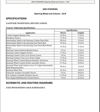
  • 1. 2005 STEERING Steering Wheel and Column - XLR SPECIFICATIONS FASTENER TIGHTENING SPECIFICATIONS Fastener Tightening Specifications SCHEMATIC AND ROUTING DIAGRAMS COLUMN/IGNITION LOCK SCHEMATICS Application Specification Metric English Column Support Bracket Nuts 24 N.m 17 lb ft Dampener Screws 1.5 N.m 13 lb in Intermediate Shaft to the Steering Column Pinch Bolt 48 N.m 35 lb ft Intermediate Shaft to the Steering Gear Pinch Bolt 34 N.m 25 lb ft Intermediate Shaft to the Steering Gear Pinch Bolt Shield Screw 3.5 N.m 31 lb in Steering Column Bottom Bracket Screw 3 N.m 27 lb in Steering Column Support Screws 17 N.m 13 lb ft Steering Column Trim Cover Screws Lower 3 N.m 27 lb in Steering Column Trim Cover Screw Upper 1.5 N.m 13 lb in Steering Wheel Control Harness Retainer And Screw 2.3 N.m 20 lb in Steering Wheel Control Switch Assembly Screws 2.3 N.m 20 lb in Steering Wheel and Column Lower To Upper Intermediate Shaft Retaining Bolts 48 N.m 35 lb ft Steering Wheel Nut 41 N.m 30 lb ft Telescope Actuator Assembly Screws 5 N.m 44 lb in Tilt Actuator Assembly Retainer Screws 1.5 N.m 13 lb in Turn Signal Multifunction Switch Screws 7 N.m 62 lb in 2005 Cadillac XLR 2005 STEERING Steering Wheel and Column - XLR 2005 Cadillac XLR 2005 STEERING Steering Wheel and Column - XLR me Friday, June 05, 2009 8:30:46 AM Page 1 © 2005 Mitchell Repair Information Company, LLC. me Friday, June 05, 2009 8:30:53 AM Page 1 © 2005 Mitchell Repair Information Company, LLC.
  • 2. Fig. 1: Column/Ignition Lock Schematics Courtesy of GENERAL MOTORS CORP. TILT/TELESCOPING STEERING COLUMN SCHEMATICS 2005 Cadillac XLR 2005 STEERING Steering Wheel and Column - XLR me Friday, June 05, 2009 8:30:46 AM Page 2 © 2005 Mitchell Repair Information Company, LLC.
  • 3. Fig. 2: Tilt/Telescoping Steering Column Schematics Courtesy of GENERAL MOTORS CORP. COMPONENT LOCATOR STEERING COLUMN DISASSEMBLED VIEW 2005 Cadillac XLR 2005 STEERING Steering Wheel and Column - XLR me Friday, June 05, 2009 8:30:46 AM Page 3 © 2005 Mitchell Repair Information Company, LLC.
  • 4. Fig. 3: Steering Column Disassembled View Courtesy of GENERAL MOTORS CORP. Callouts For Fig. 3 Callout Component Name 1 Upper Trim Cover (Kit) 2 Lower Trim Cover (Kit) 3 Steering Column Closeout Shroud 4 Flanged Prevailing Torque Nut 5 Retaining Ring 6 SIR Coil 7 Wave Washer 8 Shaft Lock Shield Assembly (Export) 9 Cam Orientation Plate 10 Turn Signal Cancel Cam Assembly 11 Upper Bearing Spring 2005 Cadillac XLR 2005 STEERING Steering Wheel and Column - XLR me Friday, June 05, 2009 8:30:46 AM Page 4 © 2005 Mitchell Repair Information Company, LLC.
  • 5. 12 Upper Bearing Inner Race Seat 13 Pan Head Tapping Screw 14 Switch Mounting Bracket 15 Inner Race 16 Washer Wiper Switch Assembly 17 Switch Mounting Bracket 18 Bearing Assembly 19 Steering Column Tilt Head Assembly 20 Bearing Assembly 21 Inner Race 22 Pan Head Tapping Screw 23 Turn Signal and Multifunction Switch Assembly 24 Power TNT Toggle Switch Assembly 25 Pan Head Tapping Screws 26 Race and Upper Shaft Assembly 27 Centering Sphere (Kit) 28 Joint Preload Spring (Kit) 29 Centering Sphere (Kit) 30 Lower Steering Shaft Assembly 31 Bolt and Retainer Assembly 32 Pinch Bolt 33 Tilt Spring 34 Lead Screw 35 TORX Head Screw 36 Tilt Support Assembly 37 Pivot Pin 38 Tilt Bumper 39 Thrust Washer 40 Thrust Bearing 41 Thrust Washer 42 Bearing Roller 43 Pivot Pin 44 TORX Head Screw 45 Thrust Washer 46 Thrust Bearing 47 Thrust Washer 48 Tilt Dampener Spacer 49 Tilt Dampener Seal 50 Lower Shield Assembly 51 Steering Column Wiring Assembly 52 Jacket Screw LH Telescoping Nut 2005 Cadillac XLR 2005 STEERING Steering Wheel and Column - XLR me Friday, June 05, 2009 8:30:46 AM Page 5 © 2005 Mitchell Repair Information Company, LLC.
  • 6. STEERING WHEEL AND COLUMN COMPONENT VIEWS Fig. 4: Lower Left of the I/P Component View Courtesy of GENERAL MOTORS CORP. Callouts For Fig. 4 53 Jacket Screw Telescoping Actuator Assembly 54 Pan Head Tapping Screw 55 Pan Head Tapping Screw 56 Telescoping Jacket Assembly 57 Retaining Ring 58 Steering Wheel Position Sensor 59 Sensor Retainer 60 Steering Shaft Seal 61 Intermediate Steering Shaft Assembly Callout Component Name 2005 Cadillac XLR 2005 STEERING Steering Wheel and Column - XLR me Friday, June 05, 2009 8:30:46 AM Page 6 © 2005 Mitchell Repair Information Company, LLC.
  • 7. Fig. 5: Identifying Steering Wheel Theft Deterrent Lock & Tilt Actuator At LR of Steering Column Courtesy of GENERAL MOTORS CORP. Callouts For Fig. 5 1 Fuel Door Release Switch 2 Rear Compartment Lid Release Switch - Inside 3 Tilt/Telescope Switch 4 Noise Compensation Microphone Callout Component Name 1 Steering Wheel Theft Deterrent Lock (Export) 2005 Cadillac XLR 2005 STEERING Steering Wheel and Column - XLR me Friday, June 05, 2009 8:30:46 AM Page 7 © 2005 Mitchell Repair Information Company, LLC.
  • 8. Fig. 6: Steering Column Lock Control Module & Telescoping Drive Motor Courtesy of GENERAL MOTORS CORP. Callouts For Fig. 6 2 Tilt Actuator Callout Component Name 1 Steering Column Lock Control Module (Export) 2 Telescoping Drive Motor 2005 Cadillac XLR 2005 STEERING Steering Wheel and Column - XLR me Friday, June 05, 2009 8:30:46 AM Page 8 © 2005 Mitchell Repair Information Company, LLC.
  • 9. Fig. 7: Modules Component View Courtesy of GENERAL MOTORS CORP. Callouts For Fig. 7 Callout Component Name 1 Folding Top Module 2 Rear Object Sensor Control Module 3 Memory Seat Module 4 Driver Door Module (DDM) 5 Radio 6 Instrument Panel Cluster (IPC) 7 Head-Up Display (HUD) 8 Remote Control Door Lock Receiver (RCDLR) 9 EBCM - BPMV 10 Distance Sensing Control Module 11 Transmission Control Module (TCM) 12 Engine Control Module (ECM) 13 Body Control Module (BCM) 2005 Cadillac XLR 2005 STEERING Steering Wheel and Column - XLR me Friday, June 05, 2009 8:30:46 AM Page 9 © 2005 Mitchell Repair Information Company, LLC.
  • 10. STEERING WHEEL AND COLUMN CONNECTOR END VIEWS Steering Column Lock Control Module C1 (Export) Connector End View Steering Column Lock Control Module C2 (Export) Connector End View 14 Audio Amplifier 15 Steering Column Lock Control Module (Export) 16 Inflatable Restraint Sensing and Diagnostic Module (SDM) 17 Front Passenger Door Module (FPDM) 18 HVAC Control Module 19 Vehicle Communication Interface Module (VCIM) 20 Antenna Ground Plane 21 Antenna Module - Right 22 Antenna Module - Left Connector Part Information  OEM: 173850  Service: NS  8-Way F Metri-Pack 280 Series (WH) Pin Wire Color Circuit No. Function A D-GN/WH 1932 Transmission Shift Select Switch (Park) Signal B RD/WH 840 Battery Positive Voltage C WH 5741 Steering Lock Control D BK 1550 Ground E PK 639 Ignition 1 Voltage F BK 1550 Ground G OG 5739 Class 2 Serial Data H - - Not Used 2005 Cadillac XLR 2005 STEERING Steering Wheel and Column - XLR me Friday, June 05, 2009 8:30:46 AM Page 10 © 2005 Mitchell Repair Information Company, LLC.
  • 11. Telescoping Drive Motor Connector End View Connector Part Information  OEM: 12064760  Service: 12085208  4-Way F Metri-Pack 150 Series (BK) Pin Wire Color Circuit No. Function A L-GN 1601 Steering Column Lock Signal B BK 150 Ground C PU 1604 Steering Column Unlock D OG 1603 Steering Column Lock Connector Part Information  OEM: 12045688  Service: 12101827  8-Way M Metri-Pack 150 Series (BK) 2005 Cadillac XLR 2005 STEERING Steering Wheel and Column - XLR me Friday, June 05, 2009 8:30:46 AM Page 11 © 2005 Mitchell Repair Information Company, LLC.
  • 12. Tilt Actuator Connector End View Tilt/Telescope Switch Connector End View Pin Wire Color Circuit No. Function A TN 2110 Steering Column Telescope Motor Control - Reverse B RD 2098 Steering Column Telescope Motor Control - Forward C OG 2153 Steering Column Telescope Sensor Signal D GY 788 5-Volt Reference E TN 782 Low Reference F-H - - Not Used Connector Part Information  OEM: 15332138  Service: NS  5-Way F Metri-Pack 280 Series (BK) Pin Wire Color Circuit No. Function A RD 2111 Steering Column Tilt Motor Control - Up B BK 2112 Steering Column Tilt Motor Control - Down C OG 2154 Steering Column Tilt Sensor Signal D GY 788 5-Volt Reference E TN 782 Low Reference 2005 Cadillac XLR 2005 STEERING Steering Wheel and Column - XLR me Friday, June 05, 2009 8:30:46 AM Page 12 © 2005 Mitchell Repair Information Company, LLC.
  • 13. DIAGNOSTIC INFORMATION AND PROCEDURES DIAGNOSTIC STARTING POINT - STEERING COLUMN Begin the system diagnosis with the Diagnostic System Check - Vehicle in Vehicle DTC Information. The Diagnostic System Check will provide the following information:  The identification of the control module which commands the system  The ability of the control module to communicate through the serial data circuit  The identification of any stored diagnostic trouble codes (DTCs) and their status The use of the diagnostic system check will identify the correct procedure for diagnosing the system and where the procedure is located. SCAN TOOL OUTPUT CONTROLS Connector Part Information  OEM: 12064763  Service: 12101876  6-Way M Metri-Pack 150 Series (GY) Pin Wire Color Circuit No. Function A GY 2096 Steering Column Tilt Up Switch Signal B YE 2097 Steering Column Tilt Down Switch Signal C OG 2095 Steering Column Tilt and Telescope Reverse Switch Signal D PK 2094 Steering Column Tilt and Telescope Forward Switch Signal E - - Not Used F RD/WH 440 Battery Positive Voltage 2005 Cadillac XLR 2005 STEERING Steering Wheel and Column - XLR me Friday, June 05, 2009 8:30:46 AM Page 13 © 2005 Mitchell Repair Information Company, LLC.
  • 14. Scan Tool Output Controls SCAN TOOL DATA LIST SCLCM Scan Tool Data List Scan Tool Output Control Additional Menu Selections Description Column Calibration Calibrate The DPM can be commanded by using the scan tool to calibrate the tilt/telescope steering wheel. This must be done every time the DPM or the tilt/telescope actuators are replaced. Column Lock Relay On/Off The BCM can be commanded by using the scan tool to energize the column lock enable circuit. Default Position Recall/Cancel The DPM can be commanded by using the scan tool to command the tilt/telescope steering wheel to the default position. Memory 1 Exit Position Recall/Cancel The DPM can be commanded by using the scan tool to command the tilt/telescope steering wheel to the number 1 exit position in the DPM memory. Memory 1 Position Recall/Cancel The DPM can be commanded by using the scan tool to command the tilt/telescope steering wheel to the number 1 position in the DPM memory. Memory 2 Exit Position Recall/Cancel The DPM can be commanded by using the scan tool to command the tilt/telescope steering wheel to the number 2 exit position in the DPM memory. Memory 2 Position Recall/Cancel The DPM can be commanded by using the scan tool to command the tilt/telescope steering wheel to the number 2 position in the DPM memory. SCLCM Setup - The SCLCM can be commanded by the scan tool to be programmed to the installed vehicle. The module will then only work on the vehicle that it was programmed. This procedure is only necessary when installing a new module. Telescope Motor Forward/Rearward The DPM can be commanded by using the scan tool to command the tilt/telescope steering wheel forward or rearward. Tilt Motor Up/Down The DPM can be commanded by using the scan tool to command the tilt/telescope steering wheel up or down. Scan Tool Parameter Data List Units Displayed Typical Data Value Turn the Ignition ON, with the Engine OFF Battery Voltage Signal SCLCM Volts 12.6 V Column Feedback Signal SCLCM Volts 11.9 V Column Lock Enable Signal SCLCM Enabled/Disabled Enabled Column Lock Module Status SCLCM Enabled/Disabled Enabled Column Lock Motor Command SCLCM Lock/Unlock/Idle/Invalid Unlock 2005 Cadillac XLR 2005 STEERING Steering Wheel and Column - XLR me Friday, June 05, 2009 8:30:46 AM Page 14 © 2005 Mitchell Repair Information Company, LLC.
  • 15. DPM Scan Tool Data List BCM Scan Tool Data List SCAN TOOL DATA DEFINITIONS SCLCM Scan Tool Data Definitions The steering column lock control module (SCLCM) Scan Tool Data Definitions contains a brief description of all steering column related SCLCM parameters available on the scan tool. Column Lock Motor Status SCLCM Lock/Unlock/Idle/Invalid Idle Column Lock Status SCLCM Varies Unlocked Ignition Voltage Signal SCLCM On/Off On Park Switch SCLCM On/Off On Password Status SCLCM Valid/Invalid/Not Programmed Valid Scan Tool Parameter Data List Units Displayed Typical Data Value Default Telescope Exit Position DPM Volts 3.76 V Default Tilt Exit Position DPM Volts 3.76 V Memory 1 Telescope Exit Position DPM Volts Varies Memory 1 Telescope Position DPM Volts Varies Memory 1 Tilt Exit Position DPM Volts Varies Memory 1 Tilt Position DPM Volts Varies Memory 2 Telescope Exit Position DPM Volts Varies Memory 2 Telescope Position DPM Volts Varies Memory 2 Tilt Exit Position DPM Volts Varies Memory 2 Tilt Position DPM Volts Varies Telescope Forward Command DPM On/Off Off Telescope Forward Switch DPM Active/Inactive Inactive Telescope Rearward Command DPM On/Off Off Telescope Rearward Switch DPM Active/Inactive Inactive Telescope Sensor DPM Volts Varies Tilt Down Command DPM On/Off Off Tilt Down Switch DPM Active/Inactive Inactive Tilt Sensor DPM Volts Varies Tilt Up Command DPM On/Off Off Tilt Up Switch DPM Active/Inactive Inactive Scan Tool Parameter Data List Units Displayed Typical Data Value Column Lock Relay Command BCM On/Off On Column Lock Relay Signal BCM On/Off On 2005 Cadillac XLR 2005 STEERING Steering Wheel and Column - XLR me Friday, June 05, 2009 8:30:46 AM Page 15 © 2005 Mitchell Repair Information Company, LLC.
  • 16. Battery Voltage Signal The scan tool displays 0-20 volts. The scan tool displays the voltage as received on the battery positive voltage circuit of the module. Column Feedback Signal The scan tool displays 0-5 volts. This data represents the signal received on the column lock motor signal circuit. Column Lock Enable Signal The scan tool displays Enabled or Disabled. This signal determines whether or not the body control module (BCM) is allowing the SCLCM to function. Column Lock Module Status The scan tool displays Enabled or Disabled, whether or not the SCLCM is functioning. Column Lock Motor Command The scan tool displays Lock, Unlock, or No Action. This data shows what the SCLCM is commanding the column lock motor. Column Lock Motor Status The scan tool displays Lock, Unlock, No Action, or Undefined. This data shows what the column lock motor is doing. Column Lock Status The scan tool displays the current column lock state. This data represents what column lock functional mode the SCLCM is in. The SCLCM enters different column lock states based upon information received from various inputs associated with the column lock system. Ignition Voltage Signal The scan tool displays ON or OFF. When the SCLCM detects ignition is present, the scan tool will display On. When the SCLCM does not detect ignition, the scan tool will display OFF. This ignition switch information is hard wired into the SCLCM. Park Switch The scan tool displays On or Off. When the transmission is placed in PARK the scan tool displays On and when the transmission is out of PARK the scan tool displays Off. 2005 Cadillac XLR 2005 STEERING Steering Wheel and Column - XLR me Friday, June 05, 2009 8:30:46 AM Page 16 © 2005 Mitchell Repair Information Company, LLC.
  • 17. Password Status The scan tool displays Valid, Invalid, or Not Programmed. The SCLCM compares the password it has to the password in the remote control door lock receiver (RCDLR) via class 2. When the password is the same then the scan tool displays Valid and when the password is different then the scan tool displays Invalid. When the SCLCM is has not been programmed the seed and key procedure to program the module has not been performed. DPM Scan Tool Data Definitions The driver position module (DPM) Scan Tool Data Definitions contains a brief description of all steering column related DPM parameters available on the scan tool. Default Telescope Exit Position The scan tool displays the default voltage value for the telescope operation in the exit position. Default Tilt Exit Position The scan tool displays the default voltage value for the tilt operation in the exit position. Memory 1 Telescope Exit Position The scan tool displays 0-5 volts. The value displayed is the telescope sensor voltage stored by the DPM and is used to recall the telescope exit position for driver 1. Memory 1 Telescope Position The scan tool displays 0-5 volts. The value displayed is the telescope sensor voltage stored by the DPM and is used to recall the telescope position for driver 1. Memory 1 Tilt Exit Position The scan tool display 0-5 volts. The value displayed is the tilt sensor voltage stored by the DPM and is used to recall the tilt exit position for driver 1. Memory 1 Tilt Position The scan tool displays 0-5 volts. The value displayed is the tilt sensor voltage stored by the DPM and is used to recall the tilt position for driver 1. Memory 2 Telescope Exit Position The scan tool displays 0-5 volts. The value displayed is the telescope sensor voltage stored by the DPM and is used to recall the telescope exit position for driver 2. Memory 2 Telescope Position 2005 Cadillac XLR 2005 STEERING Steering Wheel and Column - XLR me Friday, June 05, 2009 8:30:46 AM Page 17 © 2005 Mitchell Repair Information Company, LLC.
  • 18. The scan tool displays 0-5 volts. The value displayed is the telescope sensor voltage stored by the DPM and is used to recall the telescope position for driver 2. Memory 2 Tilt Exit Position The scan tool display 0-5 volts. The value displayed is the tilt sensor voltage stored by the DPM and is used to recall the tilt exit position for driver 2. Memory 2 Tilt Position The scan tool displays 0-5 volts. The value displayed is the tilt sensor voltage stored by the DPM and is used to recall the tilt position for driver 2. Telescope Forward Command The scan displays On or Off. The scan tool displays On when the DPM commands the telescope actuator forward. Telescope Forward Switch The scan tool displays Active or Inactive. When the switch is pressed to the forward position the scan tool displays Active. When the switch is not depressed forward the scan tool displays Inactive. Telescope Rearward Command The scan displays On or Off. The scan tool displays On when the DPM commands the telescope actuator rearward. Telescope Rearward Switch The scan tool displays Active or Inactive. When the switch is pressed to the rearward position the scan tool displays Active. When the switch is not depressed rearward the scan tool displays Inactive. Telescope Sensor The scan tool displays 0-5 volts. The value displayed is the telescope sensor signal voltage. This voltage varies when the steering column is moved forward or rearward and is used by the DPM to determine the steering column position when memory settings are stored and recalled. Tilt Down Command The scan displays On or Off. The scan tool displays On when the DPM commands the tilt actuator down. Tilt Down Switch The scan tool displays Active or Inactive. When the switch is pressed to the down position the scan tool 2005 Cadillac XLR 2005 STEERING Steering Wheel and Column - XLR me Friday, June 05, 2009 8:30:46 AM Page 18 © 2005 Mitchell Repair Information Company, LLC.
  • 19. displays Active. When the switch is not depressed down the scan tool displays Inactive. Tilt Sensor The scan tool displays 0-5 volts. The value displayed is the tilt sensor signal voltage. This voltage varies when the steering column is moved up or down and is used by the DPM to determine the steering column position when memory settings are stored and recalled. Tilt Up Switch The scan tool displays Active or Inactive. When the switch is pressed to the up position the scan tool displays Active. When the switch is not depressed up the scan tool displays Inactive. BCM Scan Tool Data Definitions The Body control module (BCM) Scan Tool Data Definitions contains a brief description of all steering column related BCM parameters available on the scan tool. Column Lock Relay Command The scan tool displays On/Off. The state displayed is the command state of the lock enable relay. This function is controlled by the BCM with data from the remote control door lock receiver (RCDLR). Column Lock Relay Signal The scan tool displays On/Off. The state displayed is the actual state of the lock enable relay. This function is controlled by the BCM with data from the RCDLR. DTC B0005 Circuit Description The steering column lock control module (SCLCM) receives a discrete input from the automatic transmission shift lever and a serial data input from the body control module (BCM). When the shift lever is in the park position, the switch internal to the automatic transmission shift lever closes sending a high input to the SCLCM. The SCLCM compares the serial data input to the discrete input. If the SCLCM receives a column lock enable command from the BCM and the transmission shift select switch park signal circuit is low, DTC B0005 will set. DTC Descriptor This diagnostic supports the following DTC: DTC B0005 In Park Switch Conditions for Running the DTC  DTCs B1327 or B1328 are not set as current. 2005 Cadillac XLR 2005 STEERING Steering Wheel and Column - XLR me Friday, June 05, 2009 8:30:46 AM Page 19 © 2005 Mitchell Repair Information Company, LLC.
  • 20.  The condition must be present for 300 ms.  The condition must be present for 5 consecutive ignition cycles. Conditions for Setting the DTC  DTC B0005 will set when the SCLCM receives a column lock enable command from the BCM and the transmission shift select switch park signal circuit is low.  There is a short to ground, or an open in the transmission shift select switch park signal circuit. Action Taken When the DTC Sets  DTC B0005 is stored in the SCLCM memory.  The SCLCM will command the driver information center (DIC) to display the Service Column Lock Now message. Conditions for Clearing the MIL/DTC  The SCLCM no longer detects a malfunction in the transmission shift select park signal circuit.  A history DTC will clear after 50 consecutive ignition cycles if the condition for the malfunction is no longer present. DTC B0005 Step Action Yes No Schematic Reference: Column/Ignition Lock Schematics Connector End View Reference: Steering Wheel and Column Connector End Views 1 Did you perform the Diagnostic System Check - Vehicle? Go to Step 2 Go to Diagnostic System Check - Vehicle in Vehicle DTC Information 2 1. Turn ON the ignition, with the engine OFF. 2. Observe the Park Switch parameter in the SCLCM data list with a scan tool. Does the scan tool display OFF? Go to Step 3 System OK 3 Test the transmission shift select switch park signal circuit for an open or short to ground. Refer to Circuit Testing and Wiring Repairs in Wiring Systems. Did you find and correct the condition? Go to Step 6 Go to Step 4 4 Inspect for poor connections at the harness connector of the steering column lock control module (SCLCM). Refer to Testing for Intermittent Conditions and Poor Connections and Connector Repairs in Wiring Systems. Did you find and correct the condition? Go to Step 6 Go to Step 5 2005 Cadillac XLR 2005 STEERING Steering Wheel and Column - XLR me Friday, June 05, 2009 8:30:46 AM Page 20 © 2005 Mitchell Repair Information Company, LLC.
  • 21. Thank you very much for your reading. Please Click Here Then Get More Information.