SlideShare a Scribd company logo
1 of 12
Download to read offline
Part No. 91764SL Rev. C
Service Manual
Hydroject Âź
3000/4000
Preface
This publications provides the service technician with
information for troubleshooting, testing, and repair of the
Hydroject. Additional information is available in the
Hydroject 3000/4000 Troubleshooting Guide, Part
No. 97928SL.
REFER TO THE HYDROJECT OPERATOR’S MAN-
UAL FOR OPERATING, MAINTENANCE AND AD-
JUSTMENT INSTRUCTIONS. Space is provided in
Chapter 2 of this book to insert the Operator’s Manual
and Parts Catalog for your machine. A replacement
Operator’s Manual is available by sending the complete
Model and Serial Number of the machine to:
The Toro Company
8111 Lyndale Avenue South
Bloomington, MN 55420
The Toro Company reserves the right to change product
specifications or this publication without notice.
means DANGER,
This safety symbol
WARNING, or CAUTION, PERSONAL SAFETY
INSTRUCTION. When you see this symbol,
carefully read the instructions that follow.
Failure to obey the instructions may result in
personal injury.
NOTE: A NOTE will give general information about the
correct operation, maintenance, service, testing or re­
pair of the machine.
IMPORTANT: The IMPORTANT notice will give im­
portant instructions which must be followed to pre­
vent damage to systems or components on the
machine.
© The Toro Company 1991-1997
Table Of Contents

Chapter 1 - Safety
Safety Instructions . . . . . . . . . . . . . . . . . . . . . . . . 1 - 1
Safety and Instruction Decals. . . . . . . . . . . . . . . . 1 - 4
Chapter 2 - Product Records and Manuals
Product Records. . . . . . . . . . . . . . . . . . . . . . . . . . 2 - 1
Equivalents and Conversions. . . . . . . . . . . . . . . . 2 - 2
Torque Specifications . . . . . . . . . . . . . . . . . . . . . . 2 - 3
Lubrication . . . . . . . . . . . . . . . . . . . . . . . . . . . . . . 2 - 4
Equipment Operation and Service History Forms 2 - 5
Chapter 3 - Engine
Specifications . . . . . . . . . . . . . . . . . . . . . . . . . . . . 3 - 1
Repairs . . . . . . . . . . . . . . . . . . . . . . . . . . . . . . . . . 3 - 2
Onan Engine Service Manual
Chapter 4 - Hydraulic System
Specifications . . . . . . . . . . . . . . . . . . . . . . . . . . . . 4 - 2
General Information . . . . . . . . . . . . . . . . . . . . . . . 4 - 3
Hydraulic Diagram . . . . . . . . . . . . . . . . . . . . . . . . 4 - 6
Special Tools . . . . . . . . . . . . . . . . . . . . . . . . . . . . 4 - 7
Troubleshooting . . . . . . . . . . . . . . . . . . . . . . . . . . 4 - 8
Testing . . . . . . . . . . . . . . . . . . . . . . . . . . . . . . . . . 4 - 9
Adjustments . . . . . . . . . . . . . . . . . . . . . . . . . . . . 4 - 11
Repairs . . . . . . . . . . . . . . . . . . . . . . . . . . . . . . . . 4 - 14
Chapter 5 - Electrical System
Wiring Schematics and Diagrams. . . . . . . . . . . . . 5 - 2
Special Tools. . . . . . . . . . . . . . . . . . . . . . . . . . . . . 5 - 7
Troubleshooting . . . . . . . . . . . . . . . . . . . . . . . . . . 5 - 9
Testing . . . . . . . . . . . . . . . . . . . . . . . . . . . . . . . . 5 - 17
Repairs . . . . . . . . . . . . . . . . . . . . . . . . . . . . . . . . 5 - 26
Chapter 6 - Water System
Specifications . . . . . . . . . . . . . . . . . . . . . . . . . . . . 6 - 2
Water System Schematic . . . . . . . . . . . . . . . . . . . 6 - 3
Special Tools. . . . . . . . . . . . . . . . . . . . . . . . . . . . . 6 - 4
Troubleshooting . . . . . . . . . . . . . . . . . . . . . . . . . . 6 - 9
Testing . . . . . . . . . . . . . . . . . . . . . . . . . . . . . . . . 6 - 12
Adjustments . . . . . . . . . . . . . . . . . . . . . . . . . . . . 6 - 18
Repairs . . . . . . . . . . . . . . . . . . . . . . . . . . . . . . . . 6 - 20
Chapter 7 - Wheels, Steering and Brakes
Adjustments . . . . . . . . . . . . . . . . . . . . . . . . . . . . . 7 - 2
Repairs . . . . . . . . . . . . . . . . . . . . . . . . . . . . . . . . . 7 - 3
Chapter 8 - Hydroject 4000 Addendum
Safety and Instruction Decals. . . . . . . . . . . . . . . . 8 - 2
Specifications . . . . . . . . . . . . . . . . . . . . . . . . . . . . 8 - 3
Maintenance Schedule . . . . . . . . . . . . . . . . . . . . . 8 - 7
Electrical Schematic . . . . . . . . . . . . . . . . . . . . . . 8 - 11
Water System Diagram. . . . . . . . . . . . . . . . . . . . 8 - 13
Service and Repairs . . . . . . . . . . . . . . . . . . . . . . 8 - 14
Hydroject 3000/4000 Rev. B
Chapter 1
Safety
Table of Contents
SAFETY INSTRUCTIONS . . . . . . . . . . . . . . . . . . . . . . 1
Before Operating . . . . . . . . . . . . . . . . . . . . . . . . . . . . 1
While Operating . . . . . . . . . . . . . . . . . . . . . . . . . . . . . 2
Safety Instructions
Although hazard control and accident prevention par-
tially are dependent upon the design and configuration
of the machine, these factors are also dependent upon
the awareness, concern, and proper training of the per-
sonnel involved in the operation, transport, mainte-
nance, and storage of the machine. Improper use or
maintenance of the machine can result in injury or
death. To reduce the potential for injury or death, comply
with the following safety instructions.
Before Operating
1. Read and understand the contents of this manual
before starting and operating the machine. Become fa-
miliar with all controls and know how to stop quickly. A
free replacement manual is available by sending com-
plete Model and Serial Numbers to:
The Toro Company

8111 Lyndale Avenue South

Bloomington, Minnesota 55420

Use the Model and Serial Number when referring to your
machine. If you have questions about this Service
Manual, please contact:
The Toro Company

Commercial Service Department

8111 Lyndale Avenue South

Bloomington, Minnesota 55420

2. Never allow children to operate the machine. Do not
allow adults to operate machine without proper instruc-
tion. Only trained operators who have read this manual
should operate this machine.
Maintenance and Service . . . . . . . . . . . . . . . . . . . . . 3
SAFETY AND INSTRUCTION DECALS . . . . . . . . . . 4
CAUTION
TO REDUCE THE POTENTIAL FOR INJURY
OR DEATH, COMPLY WITH THE FOLLOWING
SAFETY INSTRUCTIONS.
3. Never operate the machine when under the influ-
ence of drugs or alcohol.
4. Before attempting to start engine engage parking
brake.
5. Remove all debris or other objects that might inter-
fere with operation. Keep all bystanders away from the
work area.
6. Keep all shields and safety devices in place. If a
shield, safety device or decal is defective or damaged,
repair or replace it before operation is commenced. Also
tighten any loose nuts, bolts and screws to assure ma-
chine is in safe operating condition.
7. Do not operate machine while wearing sandals, ten-
nis shoes, sneakers or shorts. Also, do not wear loose
fitting clothing which could get caught in moving parts.
Always wear long pants and substantial shoes. Wearing
safety glasses, safety shoes, ear protection and a hel-
met is advisable and required by some local ordinances
and insurance regulations.
Hydroject 3000 Page 1 – 1 Rev. B Safety
8. Fill fuel tank with gasoline before starting the en-
gine. Avoid spilling gasoline. Since gasoline is flam-
mable, handle it carefully.
A.	 Use an approved gasoline container.
B.	 Do not fill tank while engine is hot or

running.

C.	 Do not smoke while handling gasoline.
D.	 Fill fuel tank outdoors and up to about one
inch (25 mm) from top of the tank, not the
filler neck.
E.	 Wipe up any spilled gasoline.
9. Check interlock switches daily for proper operation.
If a switch fails, replace it before operating the machine.
The interlock system is for your protection, so do not by-
pass it. Replace all interlock switches every two years.
While Operating
10. DON’T TAKE AN INJURY RISK! When a person or
pet appears unexpectedly in or near the WORKING
area, STOP AERATING.
11. Keep hands and feet away from nozzle and roller
area. High velocity water jets can penetrate hands and
feet. Penetration by the high velocity water jets can
cause serious personal injury. If accidental penetration
occurs, seek medical attention immediately.
12. Never use chemicals in the water supply system.
13. Do not operate water injection system on concrete
or asphalt because water jets will permanently damage
these surfaces.
14. Start engine with parking brake engaged.
15. Do not run the engine in a confined area without ad-
equate ventilation. Exhaust fumes are hazardous and
could possibly be deadly.
16. Using the machine demands attention, and to pre-
vent loss of control:
A.	 Use only in daylight or when there is good
artificial light.
B.	 Watch for holes or other hidden hazards.
C.	 Do not transport machine close to a sand
trap, ditch, creek or other hazard.
17. If the machine starts to vibrate abnormally, shut the
engine off. Remove wires from spark plugs to prevent
possibility of accidental starting. Check machine for
damage and defective parts. Repair any damage before
restarting the engine and operating the machine.
18. Do not touch engine or muffler while engine is run-
ning or soon after it is stopped. These areas could be hot
enough to cause a burn.
19. Before leaving the operator’s position–behind han-
dle–engage parking brake.
20. When leaving the machine unattended, engage
parking brake , shut engine OFF and remove key from
ignition switch.
Maintenance
21. Disconnect wires from spark plugs to prevent acci-
dental starting of the engine when servicing, adjusting or
storing the machine.
22. If machine must be tipped to perform maintenance
or an adjustment, close fuel shut–off valve, drain gaso-
line from fuel tank, oil from crankcase and remove bat-
tery.
23. To reduce potential fire hazard, keep the engine free
of excessive grease, grass, leaves and accumulations
of dirt.
24. Be sure machine is in safe operating condition by
keeping nuts, bolts and screws tight. Check all bolts and
nuts frequently to be sure they are tightened to specifi-
cation.
25. If the engine must be running to perform a mainte-
nance adjustment, keep hands, feet, clothing and other
parts of the body away from any moving parts.
26. Make sure all hydraulic line connectors are tight, and
all hydraulic hoses and lines are in good condition be-
fore applying pressure to the system.
Safety
27. Keep body and hands away from pin hole leaks or
nozzles that eject water or hydraulic fluid under high
pressure. Use paper or cardboard, not hands, to search
for leaks. Hydraulic fluid or water escaping under pres-
sure can have sufficient force to penetrate skin and do
serious damage. If either of these fluids are ejected into
the skin they must be surgically removed within a few
hours by a doctor familiar with this form of injury or gan-
grene may result.
28. Before disconnecting or performing any work on the
hydraulic oil system, all pressure in system must be re-
lieved by stopping engine and opening by–pass valve.
29. Make sure all water line connectors are tight, and all
hoses and lines are in good condition before applying
pressure to the system.
Hydroject 3000
Page 1 – 2 Rev. B
30. Before disconnecting or performing any work on the
water system, all pressure in system must be relieved by
stopping engine and opening bleed valve. Opening the
the bleed valve allows any trapped water to escape from
the system and also allows the accumulator piston to
move to the bottom of the accumulator cylinder.
31. The accumulator in this machine contains high
pressure dry nitrogen. Accumulator servicing requires
special tools and precautions. Accumulators do not con-
tain user serviceable components. Improper accumula-
tor servicing can cause dismemberment or death. Do
not attempt to disassemble a accumulator, have this
work done by a Authorized Toro Distributor.
32. Do not overspeed the engine by changing governor
settings. To be sure of safety and accuracy, have an Au-
thorized T0R0 Distributor check maximum engine
speed with a tachometer.
33. Engine must be shut off before checking oil or add-
ing oil to the crankcase.
34. Allow engine to cool before storing machine in any
enclosure such as a garage or storage shed. Make sure
the fuel tank is empty if machine is to be stored in excess
of 30 days. Do not store machine near any open flame or
where gasoline fumes may be ignited by a spark. Always
store gasoline in a safety approved, red metal container.
35. When storing or transporting machine (trailering),
make sure fuel shut–off valve is closed.
36. Perform only those maintenance instructions de-
scribed in this manual. If major repairs are ever needed
or assistance is desired, contact an Authorized Toro Dis-
tributor. To ensure optimum performance and safety, al-
ways purchase genuine TORO replacement parts and
accessories to keep the Toro all TORO. NEVER USE
“WILL–FIT” REPLACEMENT PARTS AND ACCESSO-
RIES MADE BY OTHER MANUFACTURERS. Look for
the TORO logo to assure genuineness. Using unap-
proved replacement parts and accessories could void
the warranty of The Toro Company.
Hydroject 3000 Page 1 – 3 Rev. B Safety
Lubrication
The Hydroject 3000 has 5 grease fittings that must be
lubricated every 50 hours of operation with No. 2 Gener-
al Purpose Lithium Base Grease. Lubricate all fittings
immediately after every washing, regardless of interval
listed.
The bearings and bushings that must be Iubricated are
the steering pivot shaft (Fig. 1), limit switch housing (2)
on lift arm shaft (Fig. 2) and neutral pivot shaft (Fig. 3).
1. Wipe grease fitting clean so foreign matter cannot
be forced into the bearing or bushing.
2. Pump grease into the bearing or bushing.
3. Wipe up excess grease. Figure 1
Figure 2
Figure 3
Product Records and Maintenance Page 2 – 4 Rev. B Hydroject 3000
Repairs

Engine Removal and Installation (Fig. 1)
1. Park the machine on a level surface, engage the
parking brake, and remove the hood.
2. Disconnect both the positive (+) and negative (–)
cables from the battery. Loosen the battery clamp
(Item 2) and remove the battery (Item 1).
3. Remove the drain cap (Item 33) and let the oil drain
into a container. Clean and install the drain cap.
4. Disconnect the drive coupling from the clutch adapter
(see Drive Coupling Removal and Installation in Water
System Service).
5. Remove the water pump drive belt and hydraulic
pump drive belt.
6. Disconnect the engine wiring harness connector.
Disconnect and plug the fuel hose (Item 30).
7. Remove four nuts (Item 35), washers (Item 3), cap­
screws (Item 39) and spacers (Item 38) securing the
engine to the frame.
8. Attach an engine lifting chain to the engine lifting
straps. Connect the chain to a hoist or block and tackle
and remove slack from the chain and lifting device. One
person should operate the hoist or block and tackle and
the other person should help guide the engine out of the
frame. Remove the engine from the frame.
9. Mount the engine in an engine rebuilding stand or put
it on a sturdy workbench. Before disassembling the
engine, remove external accessories, such as the muf­
fler guard (Item 11), muffler (Item 7), hydraulic pump
clutch, hydraulic pump pulley, water pump clutch and
clutch key (see Drive Coupling Removal and Installation
in Water System Service).
10. To install the engine, perform steps 2 - 9 in reverse
order. Make sure the ground cable (Item 36) is con­
nected to the frame with an engine mounting nut.
11. Replace the oil filter and fill the engine with the
correct oil.
4
3
2
1
40
39
38
3
5
26
27
28
29
30
6
7
8
9
10
31
32
33
34
35
36
37
11 12
13
14
15
16
17
18
19
5
5
3
12
9
8
18
16
35
20
21
22
23
24
25
Figure 1
Repairs Page 3 - 2 HydroJectℱ
3000
Chapter 4
Hydraulic System
Table of Contents
SPECIFICATIONS . . . . . . . . . . . . . . . . . . . . . . . . . . 2

GENERAL INFORMATION. . . . . . . . . . . . . . . . . . . . 3

Hydraulic Hose and Fitting Information . . . . . . . . 3

Pushing or Towing . . . . . . . . . . . . . . . . . . . . . . . . 5

HYDRAULIC DIAGRAM. . . . . . . . . . . . . . . . . . . . . . 6

SPECIAL TOOLS . . . . . . . . . . . . . . . . . . . . . . . . . . . 7

Hydraulic Tester. . . . . . . . . . . . . . . . . . . . . . . . . . 7

TROUBLESHOOTING . . . . . . . . . . . . . . . . . . . . . . . 8

Transmission Operates in One Direction Only . . 8

System Operates Hot, Looses Power or

Will Not Operate in Either Direction. . . . . . . . . 8

TESTING . . . . . . . . . . . . . . . . . . . . . . . . . . . . . . . . . 9

Hydraulic Tests . . . . . . . . . . . . . . . . . . . . . . . . . 10

ADJUSTMENTS. . . . . . . . . . . . . . . . . . . . . . . . . . . . 11

Traction Cable Adjustment . . . . . . . . . . . . . . . . . 11

Speed Control Adjustment. . . . . . . . . . . . . . . . . 11

Transmission Neutral Adjustment . . . . . . . . . . . 12

Aeration Speed Adjustment. . . . . . . . . . . . . . . . 12

Pump Drive Belt Adjustment . . . . . . . . . . . . . . . 13

REPAIRS . . . . . . . . . . . . . . . . . . . . . . . . . . . . . . . . 14

Pump Drive Belt Replacement . . . . . . . . . . . . . 14

Hydraulic Pump Removal and Installation. . . . . 15

Pump Shaft Seal Replacement . . . . . . . . . . . . 16

Pump Charge Check Valve Service . . . . . . . . . 17

Pump Bypass Valve Service . . . . . . . . . . . . . . . 17

Charge Pump Service . . . . . . . . . . . . . . . . . . . . 18

Major Pump Repair . . . . . . . . . . . . . . . . . . . . . . 18

Wheel Motor Removal and Installation . . . . . . . 22

Wheel Motor Repair. . . . . . . . . . . . . . . . . . . . . . 23

HydroJectℱ
3000 Page 4 - 1 Table of Contents
__________________________________________________________________________________________
________________________________________________________________________________________________________________________________________________________
________________________________________________________________________________________________________________________________________________________
________________________________________________________________________________________________________________________________________________________
Specifications

Item Description
Pump Sundstrand Series 70, BDP-10L Variable Displacement Pump
Rated system pressure 2100 PSI maximum, 1000 PSI continuous
Rated system flow 8.5 GPM maximum at 3200 RPM
Charge relief pressure 25 to 70 PSI psi at 3200 RPM
Oil filter 25 micron screw-on type. No by-pass
Wheel Motor Nichols-Gray, orbit rotor type
Hydraulic Oil * Mobil DTE 26 or equivalent
Reservoir (gear case) Approximately 4 - 5 quarts
1
2
3
* Equivalent Hydraulic Oils
(interchangeable):
Shell Tellus 68
Amoco Rykon Oil 68
Conoco Super Hydraulic Oil 68
Exxon Nuto H 68
Kendall Kenoil R & O AW 68
Pennzoil Penreco 68
Phillips Magnus A 68
Standard Energol HLP 68
Sun Sunvis 831 WR
Union Unax AW 68
Chevron AW Hydraulic Oil 68
Figure 1
1. Sight gauge
2. Fill plug
3. Breather
Specifications Page 4 - 2 HydroJectℱ
3000
Thank you very much
for your reading. Please
Click Here Then Get
More Information.
NOTE:
If there is no response to
click on the link above,
please download the PDF
document first and then
click on it.
General Information

Hydraulic Hoses
Hydraulic hoses are subject to extreme conditions such
as, pressure differentials during operation and exposure
to weather, sun, chemicals, very warm storage condi­
tions or mishandling during operation or maintenance.
These conditions can cause damage or premature de­
terioration. Some hoses, such as reel motor hoses, are
more susceptible to these conditions than others. In­
spect the hoses frequently for signs of deterioration or
damage.
When replacing a hydraulic hose, be sure that the hose
is straight (not twisted) before tightening the fittings. This
can be done by observing the imprint on the hose. Use
two wrenches; one to hold the hose straight and one to
tighten the hose swivel nut onto the fitting.
Hydraulic Fitting Installation
O-Ring Face Seal (Fig. 2, 3)
1. Make sure both threads and sealing surfaces are free
of burrs, nicks, scratches, or any foreign material.
2. Make sure the O-ring is installed and properly seated
in the groove. It is recommended that the O-ring be
replaced any time the connection is opened.
3. Lubricate the O-ring with a light coating of oil.
4. Put the tube and nut squarely into position on the face
seal end of the fitting and tighten the nut until finger tight.
5. Mark the nut and fitting body. Hold the body with a
wrench. Use another wrench to tighten the nut to the
correct flats from finger tight (F.F.F.T.). The markings on
the nut and fitting body will verify that the connection has
been tightened.
Size F.F.F.T.
4 (1/4 in. nominal hose or tubing) .75 ± .25
6 (3/8 in.) .75 ± .25
8 (1/2 in.) .75 ± .25
10 (5/8 in.) 1.00 ± .25
12 (3/4 in.) .75 ± .25
16 (1 in.) .75 ± .25
Before disconnecting or performing any work
on the hydraulic system, all pressure in the
system must be relieved by stopping the en­
gine and opening the bypass valve.
Keep body and hands away from pin hole
leaks or nozzles that eject hydraulic fluid un­
der high pressure. Use paper or cardboard,
not hands, to search for leaks. Hydraulic fluid
escaping under pressure can have sufficient
force to penetrate the skin and do serious
damage. If fluid is injected into the skin, it
must be surgically removed within a few
hours by a doctor familiar with this type of
injury or gangrene may result.
CAUTION
Nut Body
Sleeve
Seal
Figure 2
Final Initial
Mark Nut Position Position
and Body
Extend Line
Finger Tight After Proper Tightening
Figure 3
HydroJectℱ
3000 Page 4 - 3 General Information
SAE Straight Thread O-Ring Port - Non-adjustable
(Fig. 4)
1. Make sure both threads and sealing surfaces are free
of burrs, nicks, scratches, or any foreign material.
2. Always replace the O-ring seal when this type of fitting
shows signs of leakage.
3. Lubricate the O-ring with a light coating of oil.
4. Install the fitting into the port and tighten it down full
length until finger tight.
O-Ring
5. Tighten the fitting to the correct flats from finger tight
(F.F.F.T.). Figure 4
Size F.F.F.T.
4 (1/4 in. nominal hose or tubing) 1.00 ± .25

6 (3/8 in.) 1.50 ± .25

8 (1/2 in.) 1.50 ± .25

10 (5/8 in.) 1.50 ± .25

12 (3/4 in.) 1.50 ± .25

16 (1 in.) 1.50 ± .25

SAE Straight Thread O-Ring Port - Adjustable
(Fig. 5, 6)
1. Make sure both threads and sealing surfaces are free
of burrs, nicks, scratches, or any foreign material.
2. Always replace the O-ring seal when this type of fitting
shows signs of leakage.
Lock Nut
3. Lubricate the O-ring with a light coating of oil.
Back-Up Washer
4. Turn back the jam nut as far as possible. Make sure O-Ring
the back up washer is not loose and is pushed up as far
as possible (Step 1).
5. Install the fitting into the port and tighten finger tight Figure 5
until the washer contacts the face of the port (Step 2).
6. To put the fitting in the desired position, unscrew it by Step 3
Step 1
the required amount, but no more than one full turn
(Step 3).
7. Hold the fitting in the desired position with a wrench
and turn the jam nut with another wrench to the correct
flats from finger tight (F.F.F.T.) (Step 4)
Step 4
Step 2
Size F.F.F.T.
4 (1/4 in. nominal hose or tubing) 1.00 ± .25

6 (3/8 in.) 1.50 ± .25

8 (1/2 in.) 1.50 ± .25

10 (5/8 in.) 1.50 ± .25 Figure 6

12 (3/4 in.) 1.50 ± .25

16 (1 in.) 1.50 ± .25

General Information Page 4 - 4 HydroJectℱ
3000

More Related Content

More from fjsekkdkmem

Kawasaki tj27 d 2 stroke air-cooled gasoline engine service repair manual
Kawasaki tj27 d 2 stroke air-cooled gasoline engine service repair manualKawasaki tj27 d 2 stroke air-cooled gasoline engine service repair manual
Kawasaki tj27 d 2 stroke air-cooled gasoline engine service repair manualfjsekkdkmem
 
Kawasaki kel26 a handheld edger service repair manual
Kawasaki kel26 a handheld edger service repair manualKawasaki kel26 a handheld edger service repair manual
Kawasaki kel26 a handheld edger service repair manualfjsekkdkmem
 
Kawasaki kbh43 a trimmer brushcutter service repair manual
Kawasaki kbh43 a trimmer  brushcutter service repair manualKawasaki kbh43 a trimmer  brushcutter service repair manual
Kawasaki kbh43 a trimmer brushcutter service repair manualfjsekkdkmem
 
Hyster d470 (n35 zr) forklift service repair manual
Hyster d470 (n35 zr) forklift service repair manualHyster d470 (n35 zr) forklift service repair manual
Hyster d470 (n35 zr) forklift service repair manualfjsekkdkmem
 
Toro greensmaster 1600 service repair manual
Toro greensmaster 1600 service repair manualToro greensmaster 1600 service repair manual
Toro greensmaster 1600 service repair manualfjsekkdkmem
 
Stihl fs 46 trimmer service repair manual
Stihl fs 46 trimmer service repair manualStihl fs 46 trimmer service repair manual
Stihl fs 46 trimmer service repair manualfjsekkdkmem
 
New holland tvt145 tractor service repair manual
New holland tvt145 tractor service repair manualNew holland tvt145 tractor service repair manual
New holland tvt145 tractor service repair manualfjsekkdkmem
 
Cummins onan generator set with power command 3100 controller model (dqba ) s...
Cummins onan generator set with power command 3100 controller model (dqba ) s...Cummins onan generator set with power command 3100 controller model (dqba ) s...
Cummins onan generator set with power command 3100 controller model (dqba ) s...fjsekkdkmem
 
Cummins onan generator set with power command 3100 controller model (dfcc ) s...
Cummins onan generator set with power command 3100 controller model (dfcc ) s...Cummins onan generator set with power command 3100 controller model (dfcc ) s...
Cummins onan generator set with power command 3100 controller model (dfcc ) s...fjsekkdkmem
 
Cummins onan generator set with power command 3100 controller model (dfab ) s...
Cummins onan generator set with power command 3100 controller model (dfab ) s...Cummins onan generator set with power command 3100 controller model (dfab ) s...
Cummins onan generator set with power command 3100 controller model (dfab ) s...fjsekkdkmem
 
Cummins onan dqcb generator set with qsk23 g3 engine and power command 2100 c...
Cummins onan dqcb generator set with qsk23 g3 engine and power command 2100 c...Cummins onan dqcb generator set with qsk23 g3 engine and power command 2100 c...
Cummins onan dqcb generator set with qsk23 g3 engine and power command 2100 c...fjsekkdkmem
 
Case tr340 tier 4 b (final) alpha series compact track loader service repair ...
Case tr340 tier 4 b (final) alpha series compact track loader service repair ...Case tr340 tier 4 b (final) alpha series compact track loader service repair ...
Case tr340 tier 4 b (final) alpha series compact track loader service repair ...fjsekkdkmem
 
Case tr270 tier 4 b (final) alpha series compact track loader service repair ...
Case tr270 tier 4 b (final) alpha series compact track loader service repair ...Case tr270 tier 4 b (final) alpha series compact track loader service repair ...
Case tr270 tier 4 b (final) alpha series compact track loader service repair ...fjsekkdkmem
 
New holland speedrower 240 tier 3 self propelled windrower service repair man...
New holland speedrower 240 tier 3 self propelled windrower service repair man...New holland speedrower 240 tier 3 self propelled windrower service repair man...
New holland speedrower 240 tier 3 self propelled windrower service repair man...fjsekkdkmem
 
New holland speedrower 200 tier 3 self propelled windrower service repair man...
New holland speedrower 200 tier 3 self propelled windrower service repair man...New holland speedrower 200 tier 3 self propelled windrower service repair man...
New holland speedrower 200 tier 3 self propelled windrower service repair man...fjsekkdkmem
 
New holland guardian sp.400 f tier 4b (final) sprayer service repair manual (...
New holland guardian sp.400 f tier 4b (final) sprayer service repair manual (...New holland guardian sp.400 f tier 4b (final) sprayer service repair manual (...
New holland guardian sp.400 f tier 4b (final) sprayer service repair manual (...fjsekkdkmem
 
New holland 9484 tractor service repair manual
New holland 9484 tractor service repair manualNew holland 9484 tractor service repair manual
New holland 9484 tractor service repair manualfjsekkdkmem
 
Massey ferguson mf765 tractor service parts catalogue manual (part number 81...
Massey ferguson mf765 tractor service parts catalogue manual (part number  81...Massey ferguson mf765 tractor service parts catalogue manual (part number  81...
Massey ferguson mf765 tractor service parts catalogue manual (part number 81...fjsekkdkmem
 
Massey ferguson mf65 tractor service parts catalogue manual (part number 819...
Massey ferguson mf65 tractor service parts catalogue manual (part number  819...Massey ferguson mf65 tractor service parts catalogue manual (part number  819...
Massey ferguson mf65 tractor service parts catalogue manual (part number 819...fjsekkdkmem
 
Massey ferguson mf 2745 tractor service parts catalogue manual (part number ...
Massey ferguson mf 2745 tractor service parts catalogue manual (part number  ...Massey ferguson mf 2745 tractor service parts catalogue manual (part number  ...
Massey ferguson mf 2745 tractor service parts catalogue manual (part number ...fjsekkdkmem
 

More from fjsekkdkmem (20)

Kawasaki tj27 d 2 stroke air-cooled gasoline engine service repair manual
Kawasaki tj27 d 2 stroke air-cooled gasoline engine service repair manualKawasaki tj27 d 2 stroke air-cooled gasoline engine service repair manual
Kawasaki tj27 d 2 stroke air-cooled gasoline engine service repair manual
 
Kawasaki kel26 a handheld edger service repair manual
Kawasaki kel26 a handheld edger service repair manualKawasaki kel26 a handheld edger service repair manual
Kawasaki kel26 a handheld edger service repair manual
 
Kawasaki kbh43 a trimmer brushcutter service repair manual
Kawasaki kbh43 a trimmer  brushcutter service repair manualKawasaki kbh43 a trimmer  brushcutter service repair manual
Kawasaki kbh43 a trimmer brushcutter service repair manual
 
Hyster d470 (n35 zr) forklift service repair manual
Hyster d470 (n35 zr) forklift service repair manualHyster d470 (n35 zr) forklift service repair manual
Hyster d470 (n35 zr) forklift service repair manual
 
Toro greensmaster 1600 service repair manual
Toro greensmaster 1600 service repair manualToro greensmaster 1600 service repair manual
Toro greensmaster 1600 service repair manual
 
Stihl fs 46 trimmer service repair manual
Stihl fs 46 trimmer service repair manualStihl fs 46 trimmer service repair manual
Stihl fs 46 trimmer service repair manual
 
New holland tvt145 tractor service repair manual
New holland tvt145 tractor service repair manualNew holland tvt145 tractor service repair manual
New holland tvt145 tractor service repair manual
 
Cummins onan generator set with power command 3100 controller model (dqba ) s...
Cummins onan generator set with power command 3100 controller model (dqba ) s...Cummins onan generator set with power command 3100 controller model (dqba ) s...
Cummins onan generator set with power command 3100 controller model (dqba ) s...
 
Cummins onan generator set with power command 3100 controller model (dfcc ) s...
Cummins onan generator set with power command 3100 controller model (dfcc ) s...Cummins onan generator set with power command 3100 controller model (dfcc ) s...
Cummins onan generator set with power command 3100 controller model (dfcc ) s...
 
Cummins onan generator set with power command 3100 controller model (dfab ) s...
Cummins onan generator set with power command 3100 controller model (dfab ) s...Cummins onan generator set with power command 3100 controller model (dfab ) s...
Cummins onan generator set with power command 3100 controller model (dfab ) s...
 
Cummins onan dqcb generator set with qsk23 g3 engine and power command 2100 c...
Cummins onan dqcb generator set with qsk23 g3 engine and power command 2100 c...Cummins onan dqcb generator set with qsk23 g3 engine and power command 2100 c...
Cummins onan dqcb generator set with qsk23 g3 engine and power command 2100 c...
 
Case tr340 tier 4 b (final) alpha series compact track loader service repair ...
Case tr340 tier 4 b (final) alpha series compact track loader service repair ...Case tr340 tier 4 b (final) alpha series compact track loader service repair ...
Case tr340 tier 4 b (final) alpha series compact track loader service repair ...
 
Case tr270 tier 4 b (final) alpha series compact track loader service repair ...
Case tr270 tier 4 b (final) alpha series compact track loader service repair ...Case tr270 tier 4 b (final) alpha series compact track loader service repair ...
Case tr270 tier 4 b (final) alpha series compact track loader service repair ...
 
New holland speedrower 240 tier 3 self propelled windrower service repair man...
New holland speedrower 240 tier 3 self propelled windrower service repair man...New holland speedrower 240 tier 3 self propelled windrower service repair man...
New holland speedrower 240 tier 3 self propelled windrower service repair man...
 
New holland speedrower 200 tier 3 self propelled windrower service repair man...
New holland speedrower 200 tier 3 self propelled windrower service repair man...New holland speedrower 200 tier 3 self propelled windrower service repair man...
New holland speedrower 200 tier 3 self propelled windrower service repair man...
 
New holland guardian sp.400 f tier 4b (final) sprayer service repair manual (...
New holland guardian sp.400 f tier 4b (final) sprayer service repair manual (...New holland guardian sp.400 f tier 4b (final) sprayer service repair manual (...
New holland guardian sp.400 f tier 4b (final) sprayer service repair manual (...
 
New holland 9484 tractor service repair manual
New holland 9484 tractor service repair manualNew holland 9484 tractor service repair manual
New holland 9484 tractor service repair manual
 
Massey ferguson mf765 tractor service parts catalogue manual (part number 81...
Massey ferguson mf765 tractor service parts catalogue manual (part number  81...Massey ferguson mf765 tractor service parts catalogue manual (part number  81...
Massey ferguson mf765 tractor service parts catalogue manual (part number 81...
 
Massey ferguson mf65 tractor service parts catalogue manual (part number 819...
Massey ferguson mf65 tractor service parts catalogue manual (part number  819...Massey ferguson mf65 tractor service parts catalogue manual (part number  819...
Massey ferguson mf65 tractor service parts catalogue manual (part number 819...
 
Massey ferguson mf 2745 tractor service parts catalogue manual (part number ...
Massey ferguson mf 2745 tractor service parts catalogue manual (part number  ...Massey ferguson mf 2745 tractor service parts catalogue manual (part number  ...
Massey ferguson mf 2745 tractor service parts catalogue manual (part number ...
 

Recently uploaded

Dubai Call Girls Size E6 (O525547819) Call Girls In Dubai
Dubai Call Girls  Size E6 (O525547819) Call Girls In DubaiDubai Call Girls  Size E6 (O525547819) Call Girls In Dubai
Dubai Call Girls Size E6 (O525547819) Call Girls In Dubaikojalkojal131
 
(8264348440) 🔝 Call Girls In Shaheen Bagh 🔝 Delhi NCR
(8264348440) 🔝 Call Girls In Shaheen Bagh 🔝 Delhi NCR(8264348440) 🔝 Call Girls In Shaheen Bagh 🔝 Delhi NCR
(8264348440) 🔝 Call Girls In Shaheen Bagh 🔝 Delhi NCRsoniya singh
 
UNIT-1-VEHICLE STRUCTURE AND ENGINES.ppt
UNIT-1-VEHICLE STRUCTURE AND ENGINES.pptUNIT-1-VEHICLE STRUCTURE AND ENGINES.ppt
UNIT-1-VEHICLE STRUCTURE AND ENGINES.pptDineshKumar4165
 
Hyundai World Rally Team in action at 2024 WRC
Hyundai World Rally Team in action at 2024 WRCHyundai World Rally Team in action at 2024 WRC
Hyundai World Rally Team in action at 2024 WRCHyundai Motor Group
 
John Deere Tractors 5515 Diagnostic Repair Manual
John Deere Tractors 5515 Diagnostic Repair ManualJohn Deere Tractors 5515 Diagnostic Repair Manual
John Deere Tractors 5515 Diagnostic Repair ManualExcavator
 
John Deere 300 3029 4039 4045 6059 6068 Engine Operation and Service Manual
John Deere 300 3029 4039 4045 6059 6068 Engine Operation and Service ManualJohn Deere 300 3029 4039 4045 6059 6068 Engine Operation and Service Manual
John Deere 300 3029 4039 4045 6059 6068 Engine Operation and Service ManualExcavator
 
(NEHA) Call Girls Pushkar Booking Open 8617697112 Pushkar Escorts
(NEHA) Call Girls Pushkar Booking Open 8617697112 Pushkar Escorts(NEHA) Call Girls Pushkar Booking Open 8617697112 Pushkar Escorts
(NEHA) Call Girls Pushkar Booking Open 8617697112 Pushkar EscortsCall girls in Ahmedabad High profile
 
Vip Hot Call Girls đŸ«€ Mahipalpur âžĄïž 9711199171 âžĄïž Delhi đŸ«Š Whatsapp Number
Vip Hot Call Girls đŸ«€ Mahipalpur âžĄïž 9711199171 âžĄïž Delhi đŸ«Š Whatsapp NumberVip Hot Call Girls đŸ«€ Mahipalpur âžĄïž 9711199171 âžĄïž Delhi đŸ«Š Whatsapp Number
Vip Hot Call Girls đŸ«€ Mahipalpur âžĄïž 9711199171 âžĄïž Delhi đŸ«Š Whatsapp Numberkumarajju5765
 
UNIT-IV-STEERING, BRAKES AND SUSPENSION SYSTEMS.pptx
UNIT-IV-STEERING, BRAKES AND SUSPENSION SYSTEMS.pptxUNIT-IV-STEERING, BRAKES AND SUSPENSION SYSTEMS.pptx
UNIT-IV-STEERING, BRAKES AND SUSPENSION SYSTEMS.pptxDineshKumar4165
 
Transformative journey for Automotive Components Manufacturers- D&V Business ...
Transformative journey for Automotive Components Manufacturers- D&V Business ...Transformative journey for Automotive Components Manufacturers- D&V Business ...
Transformative journey for Automotive Components Manufacturers- D&V Business ...D&V Business Consulting
 
2024 WRC Hyundai World Rally Team’s i20 N Rally1 Hybrid
2024 WRC Hyundai World Rally Team’s i20 N Rally1 Hybrid2024 WRC Hyundai World Rally Team’s i20 N Rally1 Hybrid
2024 WRC Hyundai World Rally Team’s i20 N Rally1 HybridHyundai Motor Group
 
UNIT-V-ELECTRIC AND HYBRID VEHICLES.pptx
UNIT-V-ELECTRIC AND HYBRID VEHICLES.pptxUNIT-V-ELECTRIC AND HYBRID VEHICLES.pptx
UNIT-V-ELECTRIC AND HYBRID VEHICLES.pptxDineshKumar4165
 
Innovating Manufacturing with CNC Technology
Innovating Manufacturing with CNC TechnologyInnovating Manufacturing with CNC Technology
Innovating Manufacturing with CNC Technologyquickpartslimitlessm
 
The 10th anniversary, Hyundai World Rally Team's amazing journey
The 10th anniversary, Hyundai World Rally Team's amazing journeyThe 10th anniversary, Hyundai World Rally Team's amazing journey
The 10th anniversary, Hyundai World Rally Team's amazing journeyHyundai Motor Group
 
VIP Mumbai Call Girls Thakur village Just Call 9920874524 with A/C Room Cash ...
VIP Mumbai Call Girls Thakur village Just Call 9920874524 with A/C Room Cash ...VIP Mumbai Call Girls Thakur village Just Call 9920874524 with A/C Room Cash ...
VIP Mumbai Call Girls Thakur village Just Call 9920874524 with A/C Room Cash ...Garima Khatri
 
GREEN VEHICLES the kids picture show 2024
GREEN VEHICLES the kids picture show 2024GREEN VEHICLES the kids picture show 2024
GREEN VEHICLES the kids picture show 2024AHOhOops1
 
Beautiful Vip Call Girls Punjabi Bagh 9711199012 Call /Whatsapps
Beautiful Vip  Call Girls Punjabi Bagh 9711199012 Call /WhatsappsBeautiful Vip  Call Girls Punjabi Bagh 9711199012 Call /Whatsapps
Beautiful Vip Call Girls Punjabi Bagh 9711199012 Call /Whatsappssapnasaifi408
 
Delhi Call Girls Saket 9711199171 ☎✔👌✔ Full night Service for more than 1 person
Delhi Call Girls Saket 9711199171 ☎✔👌✔ Full night Service for more than 1 personDelhi Call Girls Saket 9711199171 ☎✔👌✔ Full night Service for more than 1 person
Delhi Call Girls Saket 9711199171 ☎✔👌✔ Full night Service for more than 1 personshivangimorya083
 

Recently uploaded (20)

Dubai Call Girls Size E6 (O525547819) Call Girls In Dubai
Dubai Call Girls  Size E6 (O525547819) Call Girls In DubaiDubai Call Girls  Size E6 (O525547819) Call Girls In Dubai
Dubai Call Girls Size E6 (O525547819) Call Girls In Dubai
 
(8264348440) 🔝 Call Girls In Shaheen Bagh 🔝 Delhi NCR
(8264348440) 🔝 Call Girls In Shaheen Bagh 🔝 Delhi NCR(8264348440) 🔝 Call Girls In Shaheen Bagh 🔝 Delhi NCR
(8264348440) 🔝 Call Girls In Shaheen Bagh 🔝 Delhi NCR
 
Indian Downtown Call Girls # 00971528903066 # Indian Call Girls In Downtown D...
Indian Downtown Call Girls # 00971528903066 # Indian Call Girls In Downtown D...Indian Downtown Call Girls # 00971528903066 # Indian Call Girls In Downtown D...
Indian Downtown Call Girls # 00971528903066 # Indian Call Girls In Downtown D...
 
UNIT-1-VEHICLE STRUCTURE AND ENGINES.ppt
UNIT-1-VEHICLE STRUCTURE AND ENGINES.pptUNIT-1-VEHICLE STRUCTURE AND ENGINES.ppt
UNIT-1-VEHICLE STRUCTURE AND ENGINES.ppt
 
Hyundai World Rally Team in action at 2024 WRC
Hyundai World Rally Team in action at 2024 WRCHyundai World Rally Team in action at 2024 WRC
Hyundai World Rally Team in action at 2024 WRC
 
John Deere Tractors 5515 Diagnostic Repair Manual
John Deere Tractors 5515 Diagnostic Repair ManualJohn Deere Tractors 5515 Diagnostic Repair Manual
John Deere Tractors 5515 Diagnostic Repair Manual
 
Call Girls in Shri Niwas Puri Delhi 💯Call Us 🔝9953056974🔝
Call Girls in  Shri Niwas Puri  Delhi 💯Call Us 🔝9953056974🔝Call Girls in  Shri Niwas Puri  Delhi 💯Call Us 🔝9953056974🔝
Call Girls in Shri Niwas Puri Delhi 💯Call Us 🔝9953056974🔝
 
John Deere 300 3029 4039 4045 6059 6068 Engine Operation and Service Manual
John Deere 300 3029 4039 4045 6059 6068 Engine Operation and Service ManualJohn Deere 300 3029 4039 4045 6059 6068 Engine Operation and Service Manual
John Deere 300 3029 4039 4045 6059 6068 Engine Operation and Service Manual
 
(NEHA) Call Girls Pushkar Booking Open 8617697112 Pushkar Escorts
(NEHA) Call Girls Pushkar Booking Open 8617697112 Pushkar Escorts(NEHA) Call Girls Pushkar Booking Open 8617697112 Pushkar Escorts
(NEHA) Call Girls Pushkar Booking Open 8617697112 Pushkar Escorts
 
Vip Hot Call Girls đŸ«€ Mahipalpur âžĄïž 9711199171 âžĄïž Delhi đŸ«Š Whatsapp Number
Vip Hot Call Girls đŸ«€ Mahipalpur âžĄïž 9711199171 âžĄïž Delhi đŸ«Š Whatsapp NumberVip Hot Call Girls đŸ«€ Mahipalpur âžĄïž 9711199171 âžĄïž Delhi đŸ«Š Whatsapp Number
Vip Hot Call Girls đŸ«€ Mahipalpur âžĄïž 9711199171 âžĄïž Delhi đŸ«Š Whatsapp Number
 
UNIT-IV-STEERING, BRAKES AND SUSPENSION SYSTEMS.pptx
UNIT-IV-STEERING, BRAKES AND SUSPENSION SYSTEMS.pptxUNIT-IV-STEERING, BRAKES AND SUSPENSION SYSTEMS.pptx
UNIT-IV-STEERING, BRAKES AND SUSPENSION SYSTEMS.pptx
 
Transformative journey for Automotive Components Manufacturers- D&V Business ...
Transformative journey for Automotive Components Manufacturers- D&V Business ...Transformative journey for Automotive Components Manufacturers- D&V Business ...
Transformative journey for Automotive Components Manufacturers- D&V Business ...
 
2024 WRC Hyundai World Rally Team’s i20 N Rally1 Hybrid
2024 WRC Hyundai World Rally Team’s i20 N Rally1 Hybrid2024 WRC Hyundai World Rally Team’s i20 N Rally1 Hybrid
2024 WRC Hyundai World Rally Team’s i20 N Rally1 Hybrid
 
UNIT-V-ELECTRIC AND HYBRID VEHICLES.pptx
UNIT-V-ELECTRIC AND HYBRID VEHICLES.pptxUNIT-V-ELECTRIC AND HYBRID VEHICLES.pptx
UNIT-V-ELECTRIC AND HYBRID VEHICLES.pptx
 
Innovating Manufacturing with CNC Technology
Innovating Manufacturing with CNC TechnologyInnovating Manufacturing with CNC Technology
Innovating Manufacturing with CNC Technology
 
The 10th anniversary, Hyundai World Rally Team's amazing journey
The 10th anniversary, Hyundai World Rally Team's amazing journeyThe 10th anniversary, Hyundai World Rally Team's amazing journey
The 10th anniversary, Hyundai World Rally Team's amazing journey
 
VIP Mumbai Call Girls Thakur village Just Call 9920874524 with A/C Room Cash ...
VIP Mumbai Call Girls Thakur village Just Call 9920874524 with A/C Room Cash ...VIP Mumbai Call Girls Thakur village Just Call 9920874524 with A/C Room Cash ...
VIP Mumbai Call Girls Thakur village Just Call 9920874524 with A/C Room Cash ...
 
GREEN VEHICLES the kids picture show 2024
GREEN VEHICLES the kids picture show 2024GREEN VEHICLES the kids picture show 2024
GREEN VEHICLES the kids picture show 2024
 
Beautiful Vip Call Girls Punjabi Bagh 9711199012 Call /Whatsapps
Beautiful Vip  Call Girls Punjabi Bagh 9711199012 Call /WhatsappsBeautiful Vip  Call Girls Punjabi Bagh 9711199012 Call /Whatsapps
Beautiful Vip Call Girls Punjabi Bagh 9711199012 Call /Whatsapps
 
Delhi Call Girls Saket 9711199171 ☎✔👌✔ Full night Service for more than 1 person
Delhi Call Girls Saket 9711199171 ☎✔👌✔ Full night Service for more than 1 personDelhi Call Girls Saket 9711199171 ☎✔👌✔ Full night Service for more than 1 person
Delhi Call Girls Saket 9711199171 ☎✔👌✔ Full night Service for more than 1 person
 

Toro hydroject 3000 service repair manual

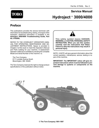
  • 1. Part No. 91764SL Rev. C Service Manual Hydroject Âź 3000/4000 Preface This publications provides the service technician with information for troubleshooting, testing, and repair of the Hydroject. Additional information is available in the Hydroject 3000/4000 Troubleshooting Guide, Part No. 97928SL. REFER TO THE HYDROJECT OPERATOR’S MAN- UAL FOR OPERATING, MAINTENANCE AND AD- JUSTMENT INSTRUCTIONS. Space is provided in Chapter 2 of this book to insert the Operator’s Manual and Parts Catalog for your machine. A replacement Operator’s Manual is available by sending the complete Model and Serial Number of the machine to: The Toro Company 8111 Lyndale Avenue South Bloomington, MN 55420 The Toro Company reserves the right to change product specifications or this publication without notice. means DANGER, This safety symbol WARNING, or CAUTION, PERSONAL SAFETY INSTRUCTION. When you see this symbol, carefully read the instructions that follow. Failure to obey the instructions may result in personal injury. NOTE: A NOTE will give general information about the correct operation, maintenance, service, testing or re­ pair of the machine. IMPORTANT: The IMPORTANT notice will give im­ portant instructions which must be followed to pre­ vent damage to systems or components on the machine. © The Toro Company 1991-1997
  • 2. Table Of Contents Chapter 1 - Safety Safety Instructions . . . . . . . . . . . . . . . . . . . . . . . . 1 - 1 Safety and Instruction Decals. . . . . . . . . . . . . . . . 1 - 4 Chapter 2 - Product Records and Manuals Product Records. . . . . . . . . . . . . . . . . . . . . . . . . . 2 - 1 Equivalents and Conversions. . . . . . . . . . . . . . . . 2 - 2 Torque Specifications . . . . . . . . . . . . . . . . . . . . . . 2 - 3 Lubrication . . . . . . . . . . . . . . . . . . . . . . . . . . . . . . 2 - 4 Equipment Operation and Service History Forms 2 - 5 Chapter 3 - Engine Specifications . . . . . . . . . . . . . . . . . . . . . . . . . . . . 3 - 1 Repairs . . . . . . . . . . . . . . . . . . . . . . . . . . . . . . . . . 3 - 2 Onan Engine Service Manual Chapter 4 - Hydraulic System Specifications . . . . . . . . . . . . . . . . . . . . . . . . . . . . 4 - 2 General Information . . . . . . . . . . . . . . . . . . . . . . . 4 - 3 Hydraulic Diagram . . . . . . . . . . . . . . . . . . . . . . . . 4 - 6 Special Tools . . . . . . . . . . . . . . . . . . . . . . . . . . . . 4 - 7 Troubleshooting . . . . . . . . . . . . . . . . . . . . . . . . . . 4 - 8 Testing . . . . . . . . . . . . . . . . . . . . . . . . . . . . . . . . . 4 - 9 Adjustments . . . . . . . . . . . . . . . . . . . . . . . . . . . . 4 - 11 Repairs . . . . . . . . . . . . . . . . . . . . . . . . . . . . . . . . 4 - 14 Chapter 5 - Electrical System Wiring Schematics and Diagrams. . . . . . . . . . . . . 5 - 2 Special Tools. . . . . . . . . . . . . . . . . . . . . . . . . . . . . 5 - 7 Troubleshooting . . . . . . . . . . . . . . . . . . . . . . . . . . 5 - 9 Testing . . . . . . . . . . . . . . . . . . . . . . . . . . . . . . . . 5 - 17 Repairs . . . . . . . . . . . . . . . . . . . . . . . . . . . . . . . . 5 - 26 Chapter 6 - Water System Specifications . . . . . . . . . . . . . . . . . . . . . . . . . . . . 6 - 2 Water System Schematic . . . . . . . . . . . . . . . . . . . 6 - 3 Special Tools. . . . . . . . . . . . . . . . . . . . . . . . . . . . . 6 - 4 Troubleshooting . . . . . . . . . . . . . . . . . . . . . . . . . . 6 - 9 Testing . . . . . . . . . . . . . . . . . . . . . . . . . . . . . . . . 6 - 12 Adjustments . . . . . . . . . . . . . . . . . . . . . . . . . . . . 6 - 18 Repairs . . . . . . . . . . . . . . . . . . . . . . . . . . . . . . . . 6 - 20 Chapter 7 - Wheels, Steering and Brakes Adjustments . . . . . . . . . . . . . . . . . . . . . . . . . . . . . 7 - 2 Repairs . . . . . . . . . . . . . . . . . . . . . . . . . . . . . . . . . 7 - 3 Chapter 8 - Hydroject 4000 Addendum Safety and Instruction Decals. . . . . . . . . . . . . . . . 8 - 2 Specifications . . . . . . . . . . . . . . . . . . . . . . . . . . . . 8 - 3 Maintenance Schedule . . . . . . . . . . . . . . . . . . . . . 8 - 7 Electrical Schematic . . . . . . . . . . . . . . . . . . . . . . 8 - 11 Water System Diagram. . . . . . . . . . . . . . . . . . . . 8 - 13 Service and Repairs . . . . . . . . . . . . . . . . . . . . . . 8 - 14 Hydroject 3000/4000 Rev. B
  • 3. Chapter 1 Safety Table of Contents SAFETY INSTRUCTIONS . . . . . . . . . . . . . . . . . . . . . . 1 Before Operating . . . . . . . . . . . . . . . . . . . . . . . . . . . . 1 While Operating . . . . . . . . . . . . . . . . . . . . . . . . . . . . . 2 Safety Instructions Although hazard control and accident prevention par- tially are dependent upon the design and configuration of the machine, these factors are also dependent upon the awareness, concern, and proper training of the per- sonnel involved in the operation, transport, mainte- nance, and storage of the machine. Improper use or maintenance of the machine can result in injury or death. To reduce the potential for injury or death, comply with the following safety instructions. Before Operating 1. Read and understand the contents of this manual before starting and operating the machine. Become fa- miliar with all controls and know how to stop quickly. A free replacement manual is available by sending com- plete Model and Serial Numbers to: The Toro Company 8111 Lyndale Avenue South Bloomington, Minnesota 55420 Use the Model and Serial Number when referring to your machine. If you have questions about this Service Manual, please contact: The Toro Company Commercial Service Department 8111 Lyndale Avenue South Bloomington, Minnesota 55420 2. Never allow children to operate the machine. Do not allow adults to operate machine without proper instruc- tion. Only trained operators who have read this manual should operate this machine. Maintenance and Service . . . . . . . . . . . . . . . . . . . . . 3 SAFETY AND INSTRUCTION DECALS . . . . . . . . . . 4 CAUTION TO REDUCE THE POTENTIAL FOR INJURY OR DEATH, COMPLY WITH THE FOLLOWING SAFETY INSTRUCTIONS. 3. Never operate the machine when under the influ- ence of drugs or alcohol. 4. Before attempting to start engine engage parking brake. 5. Remove all debris or other objects that might inter- fere with operation. Keep all bystanders away from the work area. 6. Keep all shields and safety devices in place. If a shield, safety device or decal is defective or damaged, repair or replace it before operation is commenced. Also tighten any loose nuts, bolts and screws to assure ma- chine is in safe operating condition. 7. Do not operate machine while wearing sandals, ten- nis shoes, sneakers or shorts. Also, do not wear loose fitting clothing which could get caught in moving parts. Always wear long pants and substantial shoes. Wearing safety glasses, safety shoes, ear protection and a hel- met is advisable and required by some local ordinances and insurance regulations. Hydroject 3000 Page 1 – 1 Rev. B Safety
  • 4. 8. Fill fuel tank with gasoline before starting the en- gine. Avoid spilling gasoline. Since gasoline is flam- mable, handle it carefully. A. Use an approved gasoline container. B. Do not fill tank while engine is hot or running. C. Do not smoke while handling gasoline. D. Fill fuel tank outdoors and up to about one inch (25 mm) from top of the tank, not the filler neck. E. Wipe up any spilled gasoline. 9. Check interlock switches daily for proper operation. If a switch fails, replace it before operating the machine. The interlock system is for your protection, so do not by- pass it. Replace all interlock switches every two years. While Operating 10. DON’T TAKE AN INJURY RISK! When a person or pet appears unexpectedly in or near the WORKING area, STOP AERATING. 11. Keep hands and feet away from nozzle and roller area. High velocity water jets can penetrate hands and feet. Penetration by the high velocity water jets can cause serious personal injury. If accidental penetration occurs, seek medical attention immediately. 12. Never use chemicals in the water supply system. 13. Do not operate water injection system on concrete or asphalt because water jets will permanently damage these surfaces. 14. Start engine with parking brake engaged. 15. Do not run the engine in a confined area without ad- equate ventilation. Exhaust fumes are hazardous and could possibly be deadly. 16. Using the machine demands attention, and to pre- vent loss of control: A. Use only in daylight or when there is good artificial light. B. Watch for holes or other hidden hazards. C. Do not transport machine close to a sand trap, ditch, creek or other hazard. 17. If the machine starts to vibrate abnormally, shut the engine off. Remove wires from spark plugs to prevent possibility of accidental starting. Check machine for damage and defective parts. Repair any damage before restarting the engine and operating the machine. 18. Do not touch engine or muffler while engine is run- ning or soon after it is stopped. These areas could be hot enough to cause a burn. 19. Before leaving the operator’s position–behind han- dle–engage parking brake. 20. When leaving the machine unattended, engage parking brake , shut engine OFF and remove key from ignition switch. Maintenance 21. Disconnect wires from spark plugs to prevent acci- dental starting of the engine when servicing, adjusting or storing the machine. 22. If machine must be tipped to perform maintenance or an adjustment, close fuel shut–off valve, drain gaso- line from fuel tank, oil from crankcase and remove bat- tery. 23. To reduce potential fire hazard, keep the engine free of excessive grease, grass, leaves and accumulations of dirt. 24. Be sure machine is in safe operating condition by keeping nuts, bolts and screws tight. Check all bolts and nuts frequently to be sure they are tightened to specifi- cation. 25. If the engine must be running to perform a mainte- nance adjustment, keep hands, feet, clothing and other parts of the body away from any moving parts. 26. Make sure all hydraulic line connectors are tight, and all hydraulic hoses and lines are in good condition be- fore applying pressure to the system. Safety 27. Keep body and hands away from pin hole leaks or nozzles that eject water or hydraulic fluid under high pressure. Use paper or cardboard, not hands, to search for leaks. Hydraulic fluid or water escaping under pres- sure can have sufficient force to penetrate skin and do serious damage. If either of these fluids are ejected into the skin they must be surgically removed within a few hours by a doctor familiar with this form of injury or gan- grene may result. 28. Before disconnecting or performing any work on the hydraulic oil system, all pressure in system must be re- lieved by stopping engine and opening by–pass valve. 29. Make sure all water line connectors are tight, and all hoses and lines are in good condition before applying pressure to the system. Hydroject 3000 Page 1 – 2 Rev. B
  • 5. 30. Before disconnecting or performing any work on the water system, all pressure in system must be relieved by stopping engine and opening bleed valve. Opening the the bleed valve allows any trapped water to escape from the system and also allows the accumulator piston to move to the bottom of the accumulator cylinder. 31. The accumulator in this machine contains high pressure dry nitrogen. Accumulator servicing requires special tools and precautions. Accumulators do not con- tain user serviceable components. Improper accumula- tor servicing can cause dismemberment or death. Do not attempt to disassemble a accumulator, have this work done by a Authorized Toro Distributor. 32. Do not overspeed the engine by changing governor settings. To be sure of safety and accuracy, have an Au- thorized T0R0 Distributor check maximum engine speed with a tachometer. 33. Engine must be shut off before checking oil or add- ing oil to the crankcase. 34. Allow engine to cool before storing machine in any enclosure such as a garage or storage shed. Make sure the fuel tank is empty if machine is to be stored in excess of 30 days. Do not store machine near any open flame or where gasoline fumes may be ignited by a spark. Always store gasoline in a safety approved, red metal container. 35. When storing or transporting machine (trailering), make sure fuel shut–off valve is closed. 36. Perform only those maintenance instructions de- scribed in this manual. If major repairs are ever needed or assistance is desired, contact an Authorized Toro Dis- tributor. To ensure optimum performance and safety, al- ways purchase genuine TORO replacement parts and accessories to keep the Toro all TORO. NEVER USE “WILL–FIT” REPLACEMENT PARTS AND ACCESSO- RIES MADE BY OTHER MANUFACTURERS. Look for the TORO logo to assure genuineness. Using unap- proved replacement parts and accessories could void the warranty of The Toro Company. Hydroject 3000 Page 1 – 3 Rev. B Safety
  • 6. Lubrication The Hydroject 3000 has 5 grease fittings that must be lubricated every 50 hours of operation with No. 2 Gener- al Purpose Lithium Base Grease. Lubricate all fittings immediately after every washing, regardless of interval listed. The bearings and bushings that must be Iubricated are the steering pivot shaft (Fig. 1), limit switch housing (2) on lift arm shaft (Fig. 2) and neutral pivot shaft (Fig. 3). 1. Wipe grease fitting clean so foreign matter cannot be forced into the bearing or bushing. 2. Pump grease into the bearing or bushing. 3. Wipe up excess grease. Figure 1 Figure 2 Figure 3 Product Records and Maintenance Page 2 – 4 Rev. B Hydroject 3000
  • 7. Repairs Engine Removal and Installation (Fig. 1) 1. Park the machine on a level surface, engage the parking brake, and remove the hood. 2. Disconnect both the positive (+) and negative (–) cables from the battery. Loosen the battery clamp (Item 2) and remove the battery (Item 1). 3. Remove the drain cap (Item 33) and let the oil drain into a container. Clean and install the drain cap. 4. Disconnect the drive coupling from the clutch adapter (see Drive Coupling Removal and Installation in Water System Service). 5. Remove the water pump drive belt and hydraulic pump drive belt. 6. Disconnect the engine wiring harness connector. Disconnect and plug the fuel hose (Item 30). 7. Remove four nuts (Item 35), washers (Item 3), cap­ screws (Item 39) and spacers (Item 38) securing the engine to the frame. 8. Attach an engine lifting chain to the engine lifting straps. Connect the chain to a hoist or block and tackle and remove slack from the chain and lifting device. One person should operate the hoist or block and tackle and the other person should help guide the engine out of the frame. Remove the engine from the frame. 9. Mount the engine in an engine rebuilding stand or put it on a sturdy workbench. Before disassembling the engine, remove external accessories, such as the muf­ fler guard (Item 11), muffler (Item 7), hydraulic pump clutch, hydraulic pump pulley, water pump clutch and clutch key (see Drive Coupling Removal and Installation in Water System Service). 10. To install the engine, perform steps 2 - 9 in reverse order. Make sure the ground cable (Item 36) is con­ nected to the frame with an engine mounting nut. 11. Replace the oil filter and fill the engine with the correct oil. 4 3 2 1 40 39 38 3 5 26 27 28 29 30 6 7 8 9 10 31 32 33 34 35 36 37 11 12 13 14 15 16 17 18 19 5 5 3 12 9 8 18 16 35 20 21 22 23 24 25 Figure 1 Repairs Page 3 - 2 HydroJectℱ 3000
  • 8. Chapter 4 Hydraulic System Table of Contents SPECIFICATIONS . . . . . . . . . . . . . . . . . . . . . . . . . . 2 GENERAL INFORMATION. . . . . . . . . . . . . . . . . . . . 3 Hydraulic Hose and Fitting Information . . . . . . . . 3 Pushing or Towing . . . . . . . . . . . . . . . . . . . . . . . . 5 HYDRAULIC DIAGRAM. . . . . . . . . . . . . . . . . . . . . . 6 SPECIAL TOOLS . . . . . . . . . . . . . . . . . . . . . . . . . . . 7 Hydraulic Tester. . . . . . . . . . . . . . . . . . . . . . . . . . 7 TROUBLESHOOTING . . . . . . . . . . . . . . . . . . . . . . . 8 Transmission Operates in One Direction Only . . 8 System Operates Hot, Looses Power or Will Not Operate in Either Direction. . . . . . . . . 8 TESTING . . . . . . . . . . . . . . . . . . . . . . . . . . . . . . . . . 9 Hydraulic Tests . . . . . . . . . . . . . . . . . . . . . . . . . 10 ADJUSTMENTS. . . . . . . . . . . . . . . . . . . . . . . . . . . . 11 Traction Cable Adjustment . . . . . . . . . . . . . . . . . 11 Speed Control Adjustment. . . . . . . . . . . . . . . . . 11 Transmission Neutral Adjustment . . . . . . . . . . . 12 Aeration Speed Adjustment. . . . . . . . . . . . . . . . 12 Pump Drive Belt Adjustment . . . . . . . . . . . . . . . 13 REPAIRS . . . . . . . . . . . . . . . . . . . . . . . . . . . . . . . . 14 Pump Drive Belt Replacement . . . . . . . . . . . . . 14 Hydraulic Pump Removal and Installation. . . . . 15 Pump Shaft Seal Replacement . . . . . . . . . . . . 16 Pump Charge Check Valve Service . . . . . . . . . 17 Pump Bypass Valve Service . . . . . . . . . . . . . . . 17 Charge Pump Service . . . . . . . . . . . . . . . . . . . . 18 Major Pump Repair . . . . . . . . . . . . . . . . . . . . . . 18 Wheel Motor Removal and Installation . . . . . . . 22 Wheel Motor Repair. . . . . . . . . . . . . . . . . . . . . . 23 HydroJectℱ 3000 Page 4 - 1 Table of Contents
  • 9. __________________________________________________________________________________________ ________________________________________________________________________________________________________________________________________________________ ________________________________________________________________________________________________________________________________________________________ ________________________________________________________________________________________________________________________________________________________ Specifications Item Description Pump Sundstrand Series 70, BDP-10L Variable Displacement Pump Rated system pressure 2100 PSI maximum, 1000 PSI continuous Rated system flow 8.5 GPM maximum at 3200 RPM Charge relief pressure 25 to 70 PSI psi at 3200 RPM Oil filter 25 micron screw-on type. No by-pass Wheel Motor Nichols-Gray, orbit rotor type Hydraulic Oil * Mobil DTE 26 or equivalent Reservoir (gear case) Approximately 4 - 5 quarts 1 2 3 * Equivalent Hydraulic Oils (interchangeable): Shell Tellus 68 Amoco Rykon Oil 68 Conoco Super Hydraulic Oil 68 Exxon Nuto H 68 Kendall Kenoil R & O AW 68 Pennzoil Penreco 68 Phillips Magnus A 68 Standard Energol HLP 68 Sun Sunvis 831 WR Union Unax AW 68 Chevron AW Hydraulic Oil 68 Figure 1 1. Sight gauge 2. Fill plug 3. Breather Specifications Page 4 - 2 HydroJectℱ 3000
  • 10. Thank you very much for your reading. Please Click Here Then Get More Information. NOTE: If there is no response to click on the link above, please download the PDF document first and then click on it.
  • 11. General Information Hydraulic Hoses Hydraulic hoses are subject to extreme conditions such as, pressure differentials during operation and exposure to weather, sun, chemicals, very warm storage condi­ tions or mishandling during operation or maintenance. These conditions can cause damage or premature de­ terioration. Some hoses, such as reel motor hoses, are more susceptible to these conditions than others. In­ spect the hoses frequently for signs of deterioration or damage. When replacing a hydraulic hose, be sure that the hose is straight (not twisted) before tightening the fittings. This can be done by observing the imprint on the hose. Use two wrenches; one to hold the hose straight and one to tighten the hose swivel nut onto the fitting. Hydraulic Fitting Installation O-Ring Face Seal (Fig. 2, 3) 1. Make sure both threads and sealing surfaces are free of burrs, nicks, scratches, or any foreign material. 2. Make sure the O-ring is installed and properly seated in the groove. It is recommended that the O-ring be replaced any time the connection is opened. 3. Lubricate the O-ring with a light coating of oil. 4. Put the tube and nut squarely into position on the face seal end of the fitting and tighten the nut until finger tight. 5. Mark the nut and fitting body. Hold the body with a wrench. Use another wrench to tighten the nut to the correct flats from finger tight (F.F.F.T.). The markings on the nut and fitting body will verify that the connection has been tightened. Size F.F.F.T. 4 (1/4 in. nominal hose or tubing) .75 ± .25 6 (3/8 in.) .75 ± .25 8 (1/2 in.) .75 ± .25 10 (5/8 in.) 1.00 ± .25 12 (3/4 in.) .75 ± .25 16 (1 in.) .75 ± .25 Before disconnecting or performing any work on the hydraulic system, all pressure in the system must be relieved by stopping the en­ gine and opening the bypass valve. Keep body and hands away from pin hole leaks or nozzles that eject hydraulic fluid un­ der high pressure. Use paper or cardboard, not hands, to search for leaks. Hydraulic fluid escaping under pressure can have sufficient force to penetrate the skin and do serious damage. If fluid is injected into the skin, it must be surgically removed within a few hours by a doctor familiar with this type of injury or gangrene may result. CAUTION Nut Body Sleeve Seal Figure 2 Final Initial Mark Nut Position Position and Body Extend Line Finger Tight After Proper Tightening Figure 3 HydroJectℱ 3000 Page 4 - 3 General Information
  • 12. SAE Straight Thread O-Ring Port - Non-adjustable (Fig. 4) 1. Make sure both threads and sealing surfaces are free of burrs, nicks, scratches, or any foreign material. 2. Always replace the O-ring seal when this type of fitting shows signs of leakage. 3. Lubricate the O-ring with a light coating of oil. 4. Install the fitting into the port and tighten it down full length until finger tight. O-Ring 5. Tighten the fitting to the correct flats from finger tight (F.F.F.T.). Figure 4 Size F.F.F.T. 4 (1/4 in. nominal hose or tubing) 1.00 ± .25 6 (3/8 in.) 1.50 ± .25 8 (1/2 in.) 1.50 ± .25 10 (5/8 in.) 1.50 ± .25 12 (3/4 in.) 1.50 ± .25 16 (1 in.) 1.50 ± .25 SAE Straight Thread O-Ring Port - Adjustable (Fig. 5, 6) 1. Make sure both threads and sealing surfaces are free of burrs, nicks, scratches, or any foreign material. 2. Always replace the O-ring seal when this type of fitting shows signs of leakage. Lock Nut 3. Lubricate the O-ring with a light coating of oil. Back-Up Washer 4. Turn back the jam nut as far as possible. Make sure O-Ring the back up washer is not loose and is pushed up as far as possible (Step 1). 5. Install the fitting into the port and tighten finger tight Figure 5 until the washer contacts the face of the port (Step 2). 6. To put the fitting in the desired position, unscrew it by Step 3 Step 1 the required amount, but no more than one full turn (Step 3). 7. Hold the fitting in the desired position with a wrench and turn the jam nut with another wrench to the correct flats from finger tight (F.F.F.T.) (Step 4) Step 4 Step 2 Size F.F.F.T. 4 (1/4 in. nominal hose or tubing) 1.00 ± .25 6 (3/8 in.) 1.50 ± .25 8 (1/2 in.) 1.50 ± .25 10 (5/8 in.) 1.50 ± .25 Figure 6 12 (3/4 in.) 1.50 ± .25 16 (1 in.) 1.50 ± .25 General Information Page 4 - 4 HydroJectℱ 3000