SlideShare a Scribd company logo
1 of 22
Download to read offline
TM1837 - 27ZTS Excavator
Remove and Install Fuel Injection Pump
CAUTION:
X9811-UN: High-Pressure Fluid
Escaping diesel fuel under pressure can have sufficient force to penetrate the skin, causing serious
injury. Before disconnecting lines, be sure to relieve pressure. Before applying pressure to the system,
be sure ALL connections are tight and lines, pipes and hoses are not damaged. Keep hands and body
away from pinholes and nozzles which eject fluid under pressure. Use a piece of cardboard or wood,
rather than hands, to search for suspected leaks.
If ANY fluid is injected into the skin, it must be surgically removed within a few hours by a doctor
familiar with this type of injury or gangrene may result. Doctors unfamiliar with this type of injury may
call the Deere & Company Medical Department in Moline, Illinois, or other knowledgeable medical
source.
Any time the fuel system has been opened up for service (lines disconnected or filters removed), it will be necessary to bleed
air from the system. (See Bleed Fuel System in this group.)
1/4
2019/11/19
file:///C:/ProgramData/Service%20ADVISOR/Temp/TM1837_09001faa81cb...
1.
T123181-UN: Injection Pump Injection and Supply Lines
LEGEND:
1 - Injection Line
2 - Cap Screw (4 used)
3 - Hose
4 - Clamp
5 - Washer (8 used)
6 - Supply Line
Remove fuel injection line (1).
2. Remove clamp (4) and hose (3).
3. Remove cap screws (2) and washers (5).
4. Remove fuel supply line (6).
5.
T122388-UN: Align Fuel Cut-Off Lever-to-Governor Cover
LEGEND:
2/4
2019/11/19
file:///C:/ProgramData/Service%20ADVISOR/Temp/TM1837_09001faa81cb...
1 - Pin
2 - Lever
3 - Cover
Align hole of fuel cut-off lever (2) with hole of governor cover (3) and insert pin (1) into hole.
6.
T122387-UN: Center Control Link Pin Groove
LEGEND:
1 - Control Link
2 - Injection Pump Center Position
3 - Pin
Check to see if pin groove of control link (1) is at center of injection pump (2).
NOTE:
Mark each pump to aid in assembly. Do not reuse shim; replace with same thickness.
7.
T121823-UN: Remove and Install Injection Pump
LEGEND:
3/4
2019/11/19
file:///C:/ProgramData/Service%20ADVISOR/Temp/TM1837_09001faa81cb...
1 - Nut (4 used)
2 - Injection Pump
3 - Shim
4 - Clamp
Remove nuts (1), injection pump (2), and shim (3).
NOTE:
For injection pump repair and testing, have an authorized ADS diesel injection repair station
perform the work. Unauthorized repairs made to the fuel injection pump will void warranty.
8. Install new shim (3) with same thickness as removed.
9. Install injection pump (2) making sure that rack pin is in groove of control rack before tightening injection pump.
10. Remove rack pin from fuel cut-off lever. Confirm lever moves smoothly.
11. Install fuel supply line, washers, cap screw and tighten.
12. Install hose and clamp.
13. Install fuel injection line and tighten nut.
14. Bleed fuel system. (See procedure in this group.)
Item Measurement Specification
Fuel Injection
Pump Cap Screw Torque 28 N˙m (252 lb-ft)
Item Measurement Specification
Fuel Injection
Fuel Supply Line Cap Screw Torque 24 N˙m (212 lb-in.)
Item Measurement Specification
Fuel Injection
Line Nut Torque 24 N˙m (212 lb-in.)
CED,OUOE003,10023-19-19990818
4/4
2019/11/19
file:///C:/ProgramData/Service%20ADVISOR/Temp/TM1837_09001faa81cb...
TM1837 - 27ZTS Excavator
Repair Fuel Injection Pump
IMPORTANT:
Do not disassemble the fuel injection pump further than necessary for installing available repair parts—not
even for cleaning.
Be sure that all identification numbers are legible so that pump is set to the correct specification for its
intended application.
For injection pump repair and testing, have an authorized ADS diesel injection repair station perform the work.
Unauthorized repairs made to the fuel injection pumps will void warranty.
CED,OUOE003,10024-19-19990818
1/1
2019/11/19
file:///C:/ProgramData/Service%20ADVISOR/Temp/TM1837_09001faa81cb...
TM1837 - 27ZTS Excavator
Injection Timing Test and Adjustment
T123182-UN: Remove Valve Holder from Injection Pump
LEGEND:
1 - Valve Holder
2 - Spring
3 - Injection Pump
1. Remove fuel injection line from No. 1 cylinder.
2. Remove valve holder (1) from injection pump and remove spring (2).
3. Install valve holder without spring into injection pump (3).
4. Slowly turn crankshaft pulley clockwise. At the same time continue to feed the fuel.
Stop turning crankshaft when fuel stops flowing out of No. 1 delivery valve holder.
NOTE:
This crank angle position is the starting point of injection.
1/2
2019/11/19
file:///C:/ProgramData/Service%20ADVISOR/Temp/TM1837_09001faa81cb...
5.
T123169-UN: Groove Mark and TDC Mark
LEGEND:
1 - Groove Mark
2 - TDC Mark
Note position of groove mark (1) on crankshaft pulley with TDC mark (2) on timing gear case cover.
6. Shim accordingly. Adjust timing with a shim between injection pump and cylinder block.
7. Remove valve holder and install spring.
8. Install valve holder and fuel injection line.
Item Measurement Specification
Fuel Injection
Fuel Injection Pump Timing 19° BTDC
CED,OUOE003,21117-19-20000111
2/2
2019/11/19
file:///C:/ProgramData/Service%20ADVISOR/Temp/TM1837_09001faa81cb...
TM1837 - 27ZTS Excavator
Remove and Install Fuel Injection Nozzle
CAUTION:
X9811-UN: High-Pressure Fluid
Escaping diesel fuel under pressure can have sufficient force to penetrate the skin, causing serious
injury. Before disconnecting lines, be sure to relieve pressure. Before applying pressure to the system,
be sure ALL connections are tight and lines, pipes and hoses are not damaged. Keep hands and body
away from pinholes and nozzles which eject fluid under pressure. Use a piece of cardboard or wood,
rather than hands, to search for suspected leaks.
If ANY fluid is injected into the skin, it must be surgically removed within a few hours by a doctor
familiar with this type of injury or gangrene may result. Doctors unfamiliar with this type of injury may
call the Deere & Company Medical Department in Moline, Illinois, or other knowledgeable medical
source.
Any time the fuel system has been opened up for service (lines disconnected or filters removed), it will be necessary to bleed
air from the system. (See Bleed Fuel System in this group.)
IMPORTANT:
Before removal, thoroughly remove all dirt from the cylinder head around fuel injection nozzles. Clean with
compressed air to prevent dirt from entering the cylinders. Plug the bore in the cylinder head after each nozzle
has been removed. Cap fuel line openings as soon as they are disconnected.
Do not bend the fuel delivery lines, as this may affect their durability. When loosening the fuel pressure lines,
hold male union of nozzle line stationary with a backup wrench.
1/3
2019/11/19
file:///C:/ProgramData/Service%20ADVISOR/Temp/TM1837_09001faa81cb...
1.
T123164-UN: Remove Fuel Injection and Leak-Off Line
LEGEND:
1 - Fuel Injection Line (3 used)
2 - Nut (3 used)
3 - Nozzle (3 used)
4 - Washer (3 used)
5 - Fuel Leak-Off Line
Remove fuel injection line (1) from fuel injection nozzle and fuel injection pump using a backup wrench on nozzle
connection.
NOTE:
When all fuel injection nozzles have been removed, disconnect leak-off line and remove as a
complete assembly. For individual nozzle removal, remove only the section of leak-off line
necessary for nozzle removal.
2. Remove nut (2) to remove fuel leak-off line (5). Line must be removed as an assembly. Remove washer (4).
3. Remove fuel injection nozzle (3). Protect opening to avoid contamination.
4. Repair or replace as necessary.
5. IMPORTANT:
Before installing injection nozzles, make sure nozzles are clean and free from oil or grease.
NOTE:
If nozzle bore in cylinder head must be cleaned, use a nozzle bore cleaning tool.
Install injection nozzles (3) and tighten.
6. Install washer (4) and leak-off line (5). Tighten nut (2).
Item Measurement Specification
Fuel Injection
Nozzle-to-Cylinder Head Nut Torque 49 N˙m (36 lb-ft)
Item Measurement Specification
Fuel Injection
Leak-Off Line Nut Torque 34 N˙m (301 lb-in.)
2/3
2019/11/19
file:///C:/ProgramData/Service%20ADVISOR/Temp/TM1837_09001faa81cb...
7. Install fuel injection line (1) using a backup wrench on nozzle connection.
8. Bleed fuel system. (See procedure in this group.)
Item Measurement Specification
Fuel Injection
Line Nut Torque 24 N˙m (212 lb-in.)
CED,OUOE003,21174-19-20000118
3/3
2019/11/19
file:///C:/ProgramData/Service%20ADVISOR/Temp/TM1837_09001faa81cb...
TM1837 - 27ZTS Excavator
Disassemble and Assemble Fuel Injection Nozzle
T123165-UN: Fuel Injection Nozzle
LEGEND:
1 - Retaining Nut
2 - Injection Nozzle
3 - Spring Spacer
4 - Push Rod
5 - Nozzle Assembly
6 - Shim
7 - Shim
8 - Nozzle Spring
1. Disassemble parts (1—8).
1/5
2019/11/19
file:///C:/ProgramData/Service%20ADVISOR/Temp/TM1837_09001faa81cb...
2.
T113929-UN: Check Valve Fit in Body
Remove nozzle assembly from nozzle body. Keep parts separate to maintain proper needle valve-to-body
combination.
3. Check to see if valve moves smoothly in body. If not, repair or replace nozzle.
4.
T113930-UN: Push Rod Spring
Check push rod spring for wear, weakness, and corrosion.
2/5
2019/11/19
file:///C:/ProgramData/Service%20ADVISOR/Temp/TM1837_09001faa81cb...
5.
T113931-UN: Nozzle Holder Push Rod/Needle Valve
Check nozzle holder push rod curvature.
6. Check nozzle holder push rod and needle valve contact surfaces for excessive wear and poor contact.
7.
T123166-UN: Injection Nozzle
Check injection nozzle needle valve, valve seat and injection nozzle hole for carbon deposits. If carbon deposits are
present, replace injection nozzle and needle valve.
8. Hold nozzle body vertically.
Pull needle valve out about one-third away from nozzle body.
Release needle valve.
Check that needle valve falls back into nozzle body as far as valve seat.
If needle valve does not fall back into nozzle body as far as valve seat, replace injection nozzle and needle valve.
9. NOTE:
3/5
2019/11/19
file:///C:/ProgramData/Service%20ADVISOR/Temp/TM1837_09001faa81cb...
There must be no oil on the contact surfaces of the injection nozzle and the injection nozzle
holder.
Clean these contact surfaces with diesel fuel before installation.
The nozzle dowel pin must be aligned with the dowel hole in nozzle holder body.
T113937-UN: Align Nozzle Dowel Pin to Holder Body
Install injection nozzle.
10. Install nozzle holder push rod, push rod spring, and nozzle adjusting screw.
11.
T123168-UN: Adjust Pressure
Adjust injection starting pressure using 5-8840-9016-0 nozzle tester with shims.
Item Measurement Specification
Fuel Injection
Nozzle Starting Pressure 13 238 kPa (1920 psi) (132 bar)
4/5
2019/11/19
file:///C:/ProgramData/Service%20ADVISOR/Temp/TM1837_09001faa81cb...
12.
T123167-19: Injector Nozzle Spray Conditions
Check spray condition of injection nozzle.
CED,OUOE003,10027-19-20000111
5/5
2019/11/19
file:///C:/ProgramData/Service%20ADVISOR/Temp/TM1837_09001faa81cb...
TM1837 - 27ZTS Excavator
Bleed Fuel System
Bleed Fuel System
Turn starter switch to the on position.
This will allow the fuel pump to force feed fuel to the fuel pipe and the lead-off pipe. Air in the fuel system is automatically
bled.
CED,OUOE003,10028-19-19990818
1/1
2019/11/19
file:///C:/ProgramData/Service%20ADVISOR/Temp/TM1837_09001faa81cb...
TM1837 - 27ZTS Excavator
Engine Valve Clearance Adjustment
Summary
1. Perform measurement when engine is cold.
2. Before starting work, clean head cover mounting area to avoid contamination in engine.
Preparation
1.
T123169-UN: Align TDC Mark on Crankshaft Pulley
LEGEND:
1 - TDC Mark
2 - Pointer
Locate top dead center (TDC) in compression stroke.
Align TDC (top dead center) mark (1) on crankshaft pulley with pointer (2) located on timing gear case as illustrated.
Piston No. 1 or piston No. 3 is now positioned at the TDC in its compression stroke.
2. Remove head cover.
3. Check for play in the No. 1 intake and exhaust valve rocker arms. If the No. 1 cylinder intake and exhaust valve rocker
arms have play, No. 1 piston is at TDC on the compression stroke. If the No. 1 cylinder intake and exhaust valve
rocker arms are depressed, the No. 3 piston is at TDC on the compression stroke.
4. Start measurement from cylinder (No. 1 or No. 3) positioned at TDC in compression stroke.
Measurement
1/3
2019/11/19
file:///C:/ProgramData/Service%20ADVISOR/Temp/TM1837_09001faa81cb...
T112872-UN: Measure Rocker Arm-to-Valve Stem Clearance
1. Insert a feeler gauge into clearance between rocker arm and valve stem end to measure valve clearance.
NOTE:
The cylinders are aligned from No. 1 to No. 3 in order, as viewed from the fan side.
2.
T127228-19: Valve Arrangement
Adjust the circle or double circle marked valves as shown, while the No. 1 or No. 3 cylinder is at TDC on compression
stroke.
3. Rotate crankshaft 360°. Align TDC mark with pointer. Then, continue measurement of other valves in same way.
Evaluation
Standard Valve Clearance:
Item Measurement Specification
Engine Valve Clearance Adjustment
2/3
2019/11/19
file:///C:/ProgramData/Service%20ADVISOR/Temp/TM1837_09001faa81cb...
Place the No. 1 or No. 3 cylinder at TDC by turning the crankshaft until the TDC mark on the front cover aligns with the groove
mark on the crankshaft pulley.
NOTE:
If the No. 1 cylinder intake and exhaust valve rocker arms have play, the No. 1 piston is at TDC on the
compression stroke.
If the No. 1 cylinder intake and exhaust valve rocker arms are depressed, the No. 3 piston is at TDC on
the compression stroke.
Adjustment
T112872-UN: Measure Rocker Arm-to-Valve Stem Clearance
If the measurement results are out of specification, adjust the valve clearance in the same order of measurement.
1. Loosen adjusting screw lock nuts for rocker arms.
2. Insert thickness gauge set at 0.20 mm (0.008 in.).
Adjust adjusting screws until slight drag can be felt on thickness gauge.
3. Tighten lock nuts securely.
4. Check valve clearance again after lock nuts are tightened.
Engine Intake and Exhaust
Standard Valve
Clearance 0.20 ± 0.05 mm (0.008 ± 0.002 in.)
with engine cold
Item Measurement Specification
Engine Valve Clearance Adjustment
Engine Intake and Exhaust
Standard Valve
Clearance 0.20 ± 0.05 mm (0.008 ± 0.002 in.)
with engine cold
CED,OUOE003,21120-19-20000111
3/3
2019/11/19
file:///C:/ProgramData/Service%20ADVISOR/Temp/TM1837_09001faa81cb...
Thank you very much for
your reading. Please Click
Here. Then Get COMPLETE
MANUAL. NO WAITING
NOTE:
If there is no response to
click on the link above,
please download the PDF
document first and then
click on it.
TM1837 - 27ZTS Excavator
Remove and Install Starter
T125137-UN: Starter
LEGEND:
1 - Electrical Connector
2 - Nut
3 - Cap Screw
4 - Nut
IMPORTANT:
Always disconnect the negative (-) battery cables before removing starter or a short circuit could result.
1. Disconnect negative (-) battery cables.
2. Remove seat. (See procedure in Group 1821.)
3. Remove seat base. (See procedure in Group 1821.)
4. Disconnect electrical connector (1).
5. Remove nut (4). Remove battery cable.
1/2
2019/11/19
file:///C:/ProgramData/Service%20ADVISOR/Temp/TM1837_09001faa81cb...
6. Remove cap screw (3).
7. Remove nut (2). Remove starter.
8. Replace parts as necessary.
9. Install starter. Tighten cap screw (3).
10. Connect wiring leads.
11. Connect negative (-) battery cables.
Item Measurement Specification
Starter
Starter-to-Flywheel Housing Cap
Screw
Torque 13 N˙m (115 lb-in.)
CED,OUOE003,21121-19-20000111
2/2
2019/11/19
file:///C:/ProgramData/Service%20ADVISOR/Temp/TM1837_09001faa81cb...

More Related Content

More from fjkksekdmdm

John Deere 8260R Tractors Service Repair Technical Manual (TM110319).pdf
John Deere 8260R Tractors Service Repair Technical Manual (TM110319).pdfJohn Deere 8260R Tractors Service Repair Technical Manual (TM110319).pdf
John Deere 8260R Tractors Service Repair Technical Manual (TM110319).pdffjkksekdmdm
 
John Deere 8285R Tractors Service Repair Technical Manual (TM110319).pdf
John Deere 8285R Tractors Service Repair Technical Manual (TM110319).pdfJohn Deere 8285R Tractors Service Repair Technical Manual (TM110319).pdf
John Deere 8285R Tractors Service Repair Technical Manual (TM110319).pdffjkksekdmdm
 
John Deere 6200 Tractors Service Repair Technical Manual (TM4493).pdf
John Deere 6200 Tractors Service Repair Technical Manual (TM4493).pdfJohn Deere 6200 Tractors Service Repair Technical Manual (TM4493).pdf
John Deere 6200 Tractors Service Repair Technical Manual (TM4493).pdffjkksekdmdm
 
John Deere 6500 Tractors Service Repair Technical Manual (TM4523).pdf
John Deere 6500 Tractors Service Repair Technical Manual (TM4523).pdfJohn Deere 6500 Tractors Service Repair Technical Manual (TM4523).pdf
John Deere 6500 Tractors Service Repair Technical Manual (TM4523).pdffjkksekdmdm
 
John Deere 6506 Tractors Service Repair Technical Manual (TM4493).pdf
John Deere 6506 Tractors Service Repair Technical Manual (TM4493).pdfJohn Deere 6506 Tractors Service Repair Technical Manual (TM4493).pdf
John Deere 6506 Tractors Service Repair Technical Manual (TM4493).pdffjkksekdmdm
 
John Deere 6600 Tractors Service Repair Technical Manual (TM4493).pdf
John Deere 6600 Tractors Service Repair Technical Manual (TM4493).pdfJohn Deere 6600 Tractors Service Repair Technical Manual (TM4493).pdf
John Deere 6600 Tractors Service Repair Technical Manual (TM4493).pdffjkksekdmdm
 
John Deere 6500L Tractors Service Repair Technical Manual (TM4523).pdf
John Deere 6500L Tractors Service Repair Technical Manual (TM4523).pdfJohn Deere 6500L Tractors Service Repair Technical Manual (TM4523).pdf
John Deere 6500L Tractors Service Repair Technical Manual (TM4523).pdffjkksekdmdm
 
John Deere 6300 Tractors Service Repair Technical Manual (TM4493).pdf
John Deere 6300 Tractors Service Repair Technical Manual (TM4493).pdfJohn Deere 6300 Tractors Service Repair Technical Manual (TM4493).pdf
John Deere 6300 Tractors Service Repair Technical Manual (TM4493).pdffjkksekdmdm
 
John Deere 6400 Tractors Service Repair Technical Manual (TM4523).pdf
John Deere 6400 Tractors Service Repair Technical Manual (TM4523).pdfJohn Deere 6400 Tractors Service Repair Technical Manual (TM4523).pdf
John Deere 6400 Tractors Service Repair Technical Manual (TM4523).pdffjkksekdmdm
 
John Deere 6200L Tractors Service Repair Technical Manual (TM4523).pdf
John Deere 6200L Tractors Service Repair Technical Manual (TM4523).pdfJohn Deere 6200L Tractors Service Repair Technical Manual (TM4523).pdf
John Deere 6200L Tractors Service Repair Technical Manual (TM4523).pdffjkksekdmdm
 
John Deere 6400L Tractors Service Repair Technical Manual (TM4523).pdf
John Deere 6400L Tractors Service Repair Technical Manual (TM4523).pdfJohn Deere 6400L Tractors Service Repair Technical Manual (TM4523).pdf
John Deere 6400L Tractors Service Repair Technical Manual (TM4523).pdffjkksekdmdm
 
John Deere 6200 Tractors Service Repair Technical Manual (TM4523).pdf
John Deere 6200 Tractors Service Repair Technical Manual (TM4523).pdfJohn Deere 6200 Tractors Service Repair Technical Manual (TM4523).pdf
John Deere 6200 Tractors Service Repair Technical Manual (TM4523).pdffjkksekdmdm
 
John Deere 6100 Tractors Service Repair Technical Manual (TM4493).pdf
John Deere 6100 Tractors Service Repair Technical Manual (TM4493).pdfJohn Deere 6100 Tractors Service Repair Technical Manual (TM4493).pdf
John Deere 6100 Tractors Service Repair Technical Manual (TM4493).pdffjkksekdmdm
 
John Deere 6110D (Tier 0 - Tier 3Stage IIIA) Tractors Service Repair Technica...
John Deere 6110D (Tier 0 - Tier 3Stage IIIA) Tractors Service Repair Technica...John Deere 6110D (Tier 0 - Tier 3Stage IIIA) Tractors Service Repair Technica...
John Deere 6110D (Tier 0 - Tier 3Stage IIIA) Tractors Service Repair Technica...fjkksekdmdm
 
John Deere 6130D (Tier 0 - Tier 3Stage IIIA) Tractors Service Repair Technica...
John Deere 6130D (Tier 0 - Tier 3Stage IIIA) Tractors Service Repair Technica...John Deere 6130D (Tier 0 - Tier 3Stage IIIA) Tractors Service Repair Technica...
John Deere 6130D (Tier 0 - Tier 3Stage IIIA) Tractors Service Repair Technica...fjkksekdmdm
 
John Deere 6125D (Tier 0 - Tier 3Stage IIIA) Tractors Service Repair Technica...
John Deere 6125D (Tier 0 - Tier 3Stage IIIA) Tractors Service Repair Technica...John Deere 6125D (Tier 0 - Tier 3Stage IIIA) Tractors Service Repair Technica...
John Deere 6125D (Tier 0 - Tier 3Stage IIIA) Tractors Service Repair Technica...fjkksekdmdm
 
John Deere 6115D (Tier 0 - Tier 3Stage IIIA) Tractors Service Repair Technica...
John Deere 6115D (Tier 0 - Tier 3Stage IIIA) Tractors Service Repair Technica...John Deere 6115D (Tier 0 - Tier 3Stage IIIA) Tractors Service Repair Technica...
John Deere 6115D (Tier 0 - Tier 3Stage IIIA) Tractors Service Repair Technica...fjkksekdmdm
 
John Deere 6100D (Tier 0 - Tier 3Stage IIIA) Tractors Service Repair Technica...
John Deere 6100D (Tier 0 - Tier 3Stage IIIA) Tractors Service Repair Technica...John Deere 6100D (Tier 0 - Tier 3Stage IIIA) Tractors Service Repair Technica...
John Deere 6100D (Tier 0 - Tier 3Stage IIIA) Tractors Service Repair Technica...fjkksekdmdm
 
John Deere 1800 Utility Vehicle Service Repair Manual (TM1527).pdf
John Deere 1800 Utility Vehicle Service Repair Manual (TM1527).pdfJohn Deere 1800 Utility Vehicle Service Repair Manual (TM1527).pdf
John Deere 1800 Utility Vehicle Service Repair Manual (TM1527).pdffjkksekdmdm
 
John Deere 300D Backhoe Loaders Service Repair Technical Manual (TM1497).pdf
John Deere 300D Backhoe Loaders Service Repair Technical Manual (TM1497).pdfJohn Deere 300D Backhoe Loaders Service Repair Technical Manual (TM1497).pdf
John Deere 300D Backhoe Loaders Service Repair Technical Manual (TM1497).pdffjkksekdmdm
 

More from fjkksekdmdm (20)

John Deere 8260R Tractors Service Repair Technical Manual (TM110319).pdf
John Deere 8260R Tractors Service Repair Technical Manual (TM110319).pdfJohn Deere 8260R Tractors Service Repair Technical Manual (TM110319).pdf
John Deere 8260R Tractors Service Repair Technical Manual (TM110319).pdf
 
John Deere 8285R Tractors Service Repair Technical Manual (TM110319).pdf
John Deere 8285R Tractors Service Repair Technical Manual (TM110319).pdfJohn Deere 8285R Tractors Service Repair Technical Manual (TM110319).pdf
John Deere 8285R Tractors Service Repair Technical Manual (TM110319).pdf
 
John Deere 6200 Tractors Service Repair Technical Manual (TM4493).pdf
John Deere 6200 Tractors Service Repair Technical Manual (TM4493).pdfJohn Deere 6200 Tractors Service Repair Technical Manual (TM4493).pdf
John Deere 6200 Tractors Service Repair Technical Manual (TM4493).pdf
 
John Deere 6500 Tractors Service Repair Technical Manual (TM4523).pdf
John Deere 6500 Tractors Service Repair Technical Manual (TM4523).pdfJohn Deere 6500 Tractors Service Repair Technical Manual (TM4523).pdf
John Deere 6500 Tractors Service Repair Technical Manual (TM4523).pdf
 
John Deere 6506 Tractors Service Repair Technical Manual (TM4493).pdf
John Deere 6506 Tractors Service Repair Technical Manual (TM4493).pdfJohn Deere 6506 Tractors Service Repair Technical Manual (TM4493).pdf
John Deere 6506 Tractors Service Repair Technical Manual (TM4493).pdf
 
John Deere 6600 Tractors Service Repair Technical Manual (TM4493).pdf
John Deere 6600 Tractors Service Repair Technical Manual (TM4493).pdfJohn Deere 6600 Tractors Service Repair Technical Manual (TM4493).pdf
John Deere 6600 Tractors Service Repair Technical Manual (TM4493).pdf
 
John Deere 6500L Tractors Service Repair Technical Manual (TM4523).pdf
John Deere 6500L Tractors Service Repair Technical Manual (TM4523).pdfJohn Deere 6500L Tractors Service Repair Technical Manual (TM4523).pdf
John Deere 6500L Tractors Service Repair Technical Manual (TM4523).pdf
 
John Deere 6300 Tractors Service Repair Technical Manual (TM4493).pdf
John Deere 6300 Tractors Service Repair Technical Manual (TM4493).pdfJohn Deere 6300 Tractors Service Repair Technical Manual (TM4493).pdf
John Deere 6300 Tractors Service Repair Technical Manual (TM4493).pdf
 
John Deere 6400 Tractors Service Repair Technical Manual (TM4523).pdf
John Deere 6400 Tractors Service Repair Technical Manual (TM4523).pdfJohn Deere 6400 Tractors Service Repair Technical Manual (TM4523).pdf
John Deere 6400 Tractors Service Repair Technical Manual (TM4523).pdf
 
John Deere 6200L Tractors Service Repair Technical Manual (TM4523).pdf
John Deere 6200L Tractors Service Repair Technical Manual (TM4523).pdfJohn Deere 6200L Tractors Service Repair Technical Manual (TM4523).pdf
John Deere 6200L Tractors Service Repair Technical Manual (TM4523).pdf
 
John Deere 6400L Tractors Service Repair Technical Manual (TM4523).pdf
John Deere 6400L Tractors Service Repair Technical Manual (TM4523).pdfJohn Deere 6400L Tractors Service Repair Technical Manual (TM4523).pdf
John Deere 6400L Tractors Service Repair Technical Manual (TM4523).pdf
 
John Deere 6200 Tractors Service Repair Technical Manual (TM4523).pdf
John Deere 6200 Tractors Service Repair Technical Manual (TM4523).pdfJohn Deere 6200 Tractors Service Repair Technical Manual (TM4523).pdf
John Deere 6200 Tractors Service Repair Technical Manual (TM4523).pdf
 
John Deere 6100 Tractors Service Repair Technical Manual (TM4493).pdf
John Deere 6100 Tractors Service Repair Technical Manual (TM4493).pdfJohn Deere 6100 Tractors Service Repair Technical Manual (TM4493).pdf
John Deere 6100 Tractors Service Repair Technical Manual (TM4493).pdf
 
John Deere 6110D (Tier 0 - Tier 3Stage IIIA) Tractors Service Repair Technica...
John Deere 6110D (Tier 0 - Tier 3Stage IIIA) Tractors Service Repair Technica...John Deere 6110D (Tier 0 - Tier 3Stage IIIA) Tractors Service Repair Technica...
John Deere 6110D (Tier 0 - Tier 3Stage IIIA) Tractors Service Repair Technica...
 
John Deere 6130D (Tier 0 - Tier 3Stage IIIA) Tractors Service Repair Technica...
John Deere 6130D (Tier 0 - Tier 3Stage IIIA) Tractors Service Repair Technica...John Deere 6130D (Tier 0 - Tier 3Stage IIIA) Tractors Service Repair Technica...
John Deere 6130D (Tier 0 - Tier 3Stage IIIA) Tractors Service Repair Technica...
 
John Deere 6125D (Tier 0 - Tier 3Stage IIIA) Tractors Service Repair Technica...
John Deere 6125D (Tier 0 - Tier 3Stage IIIA) Tractors Service Repair Technica...John Deere 6125D (Tier 0 - Tier 3Stage IIIA) Tractors Service Repair Technica...
John Deere 6125D (Tier 0 - Tier 3Stage IIIA) Tractors Service Repair Technica...
 
John Deere 6115D (Tier 0 - Tier 3Stage IIIA) Tractors Service Repair Technica...
John Deere 6115D (Tier 0 - Tier 3Stage IIIA) Tractors Service Repair Technica...John Deere 6115D (Tier 0 - Tier 3Stage IIIA) Tractors Service Repair Technica...
John Deere 6115D (Tier 0 - Tier 3Stage IIIA) Tractors Service Repair Technica...
 
John Deere 6100D (Tier 0 - Tier 3Stage IIIA) Tractors Service Repair Technica...
John Deere 6100D (Tier 0 - Tier 3Stage IIIA) Tractors Service Repair Technica...John Deere 6100D (Tier 0 - Tier 3Stage IIIA) Tractors Service Repair Technica...
John Deere 6100D (Tier 0 - Tier 3Stage IIIA) Tractors Service Repair Technica...
 
John Deere 1800 Utility Vehicle Service Repair Manual (TM1527).pdf
John Deere 1800 Utility Vehicle Service Repair Manual (TM1527).pdfJohn Deere 1800 Utility Vehicle Service Repair Manual (TM1527).pdf
John Deere 1800 Utility Vehicle Service Repair Manual (TM1527).pdf
 
John Deere 300D Backhoe Loaders Service Repair Technical Manual (TM1497).pdf
John Deere 300D Backhoe Loaders Service Repair Technical Manual (TM1497).pdfJohn Deere 300D Backhoe Loaders Service Repair Technical Manual (TM1497).pdf
John Deere 300D Backhoe Loaders Service Repair Technical Manual (TM1497).pdf
 

Recently uploaded

UNIT-1-VEHICLE STRUCTURE AND ENGINES.ppt
UNIT-1-VEHICLE STRUCTURE AND ENGINES.pptUNIT-1-VEHICLE STRUCTURE AND ENGINES.ppt
UNIT-1-VEHICLE STRUCTURE AND ENGINES.pptDineshKumar4165
 
Not Sure About VW EGR Valve Health Look For These Symptoms
Not Sure About VW EGR Valve Health Look For These SymptomsNot Sure About VW EGR Valve Health Look For These Symptoms
Not Sure About VW EGR Valve Health Look For These SymptomsFifth Gear Automotive
 
Call Girls in Karachi | +923081633338 | Karachi Call Girls
Call Girls in Karachi  | +923081633338 | Karachi Call GirlsCall Girls in Karachi  | +923081633338 | Karachi Call Girls
Call Girls in Karachi | +923081633338 | Karachi Call GirlsAyesha Khan
 
GREEN VEHICLES the kids picture show 2024
GREEN VEHICLES the kids picture show 2024GREEN VEHICLES the kids picture show 2024
GREEN VEHICLES the kids picture show 2024AHOhOops1
 
Digamma / CertiCon Company Presentation
Digamma / CertiCon Company  PresentationDigamma / CertiCon Company  Presentation
Digamma / CertiCon Company PresentationMihajloManjak
 
VIP Kolkata Call Girl Kasba 👉 8250192130 Available With Room
VIP Kolkata Call Girl Kasba 👉 8250192130  Available With RoomVIP Kolkata Call Girl Kasba 👉 8250192130  Available With Room
VIP Kolkata Call Girl Kasba 👉 8250192130 Available With Roomdivyansh0kumar0
 
原版1:1复刻俄亥俄州立大学毕业证OSU毕业证留信学历认证
原版1:1复刻俄亥俄州立大学毕业证OSU毕业证留信学历认证原版1:1复刻俄亥俄州立大学毕业证OSU毕业证留信学历认证
原版1:1复刻俄亥俄州立大学毕业证OSU毕业证留信学历认证jdkhjh
 
907MTAMount Coventry University Bachelor's Diploma in Engineering
907MTAMount Coventry University Bachelor's Diploma in Engineering907MTAMount Coventry University Bachelor's Diploma in Engineering
907MTAMount Coventry University Bachelor's Diploma in EngineeringFi sss
 
Digamma - CertiCon Team Skills and Qualifications
Digamma - CertiCon Team Skills and QualificationsDigamma - CertiCon Team Skills and Qualifications
Digamma - CertiCon Team Skills and QualificationsMihajloManjak
 
办理萨省大学毕业证成绩单|购买加拿大USASK文凭证书
办理萨省大学毕业证成绩单|购买加拿大USASK文凭证书办理萨省大学毕业证成绩单|购买加拿大USASK文凭证书
办理萨省大学毕业证成绩单|购买加拿大USASK文凭证书zdzoqco
 
John Deere 300 3029 4039 4045 6059 6068 Engine Operation and Service Manual
John Deere 300 3029 4039 4045 6059 6068 Engine Operation and Service ManualJohn Deere 300 3029 4039 4045 6059 6068 Engine Operation and Service Manual
John Deere 300 3029 4039 4045 6059 6068 Engine Operation and Service ManualExcavator
 
如何办理迈阿密大学毕业证(UM毕业证)成绩单留信学历认证原版一比一
如何办理迈阿密大学毕业证(UM毕业证)成绩单留信学历认证原版一比一如何办理迈阿密大学毕业证(UM毕业证)成绩单留信学历认证原版一比一
如何办理迈阿密大学毕业证(UM毕业证)成绩单留信学历认证原版一比一ga6c6bdl
 
Dubai Call Girls Services Call 09900000000
Dubai Call Girls Services Call 09900000000Dubai Call Girls Services Call 09900000000
Dubai Call Girls Services Call 09900000000Komal Khan
 
(办理学位证)(Toledo毕业证)托莱多大学毕业证成绩单修改留信学历认证原版一模一样
(办理学位证)(Toledo毕业证)托莱多大学毕业证成绩单修改留信学历认证原版一模一样(办理学位证)(Toledo毕业证)托莱多大学毕业证成绩单修改留信学历认证原版一模一样
(办理学位证)(Toledo毕业证)托莱多大学毕业证成绩单修改留信学历认证原版一模一样gfghbihg
 
办理克莱姆森大学毕业证成绩单|购买美国文凭证书
办理克莱姆森大学毕业证成绩单|购买美国文凭证书办理克莱姆森大学毕业证成绩单|购买美国文凭证书
办理克莱姆森大学毕业证成绩单|购买美国文凭证书zdzoqco
 
UNIT-II-ENGINE AUXILIARY SYSTEMS &TURBOCHARGER
UNIT-II-ENGINE AUXILIARY SYSTEMS &TURBOCHARGERUNIT-II-ENGINE AUXILIARY SYSTEMS &TURBOCHARGER
UNIT-II-ENGINE AUXILIARY SYSTEMS &TURBOCHARGERDineshKumar4165
 
FULL ENJOY - 9953040155 Call Girls in Sector 61 | Noida
FULL ENJOY - 9953040155 Call Girls in Sector 61 | NoidaFULL ENJOY - 9953040155 Call Girls in Sector 61 | Noida
FULL ENJOY - 9953040155 Call Girls in Sector 61 | NoidaMalviyaNagarCallGirl
 
UNIT-III-TRANSMISSION SYSTEMS REAR AXLES
UNIT-III-TRANSMISSION SYSTEMS REAR AXLESUNIT-III-TRANSMISSION SYSTEMS REAR AXLES
UNIT-III-TRANSMISSION SYSTEMS REAR AXLESDineshKumar4165
 

Recently uploaded (20)

UNIT-1-VEHICLE STRUCTURE AND ENGINES.ppt
UNIT-1-VEHICLE STRUCTURE AND ENGINES.pptUNIT-1-VEHICLE STRUCTURE AND ENGINES.ppt
UNIT-1-VEHICLE STRUCTURE AND ENGINES.ppt
 
Not Sure About VW EGR Valve Health Look For These Symptoms
Not Sure About VW EGR Valve Health Look For These SymptomsNot Sure About VW EGR Valve Health Look For These Symptoms
Not Sure About VW EGR Valve Health Look For These Symptoms
 
Indian Downtown Call Girls # 00971528903066 # Indian Call Girls In Downtown D...
Indian Downtown Call Girls # 00971528903066 # Indian Call Girls In Downtown D...Indian Downtown Call Girls # 00971528903066 # Indian Call Girls In Downtown D...
Indian Downtown Call Girls # 00971528903066 # Indian Call Girls In Downtown D...
 
Call Girls in Karachi | +923081633338 | Karachi Call Girls
Call Girls in Karachi  | +923081633338 | Karachi Call GirlsCall Girls in Karachi  | +923081633338 | Karachi Call Girls
Call Girls in Karachi | +923081633338 | Karachi Call Girls
 
GREEN VEHICLES the kids picture show 2024
GREEN VEHICLES the kids picture show 2024GREEN VEHICLES the kids picture show 2024
GREEN VEHICLES the kids picture show 2024
 
Digamma / CertiCon Company Presentation
Digamma / CertiCon Company  PresentationDigamma / CertiCon Company  Presentation
Digamma / CertiCon Company Presentation
 
VIP Kolkata Call Girl Kasba 👉 8250192130 Available With Room
VIP Kolkata Call Girl Kasba 👉 8250192130  Available With RoomVIP Kolkata Call Girl Kasba 👉 8250192130  Available With Room
VIP Kolkata Call Girl Kasba 👉 8250192130 Available With Room
 
原版1:1复刻俄亥俄州立大学毕业证OSU毕业证留信学历认证
原版1:1复刻俄亥俄州立大学毕业证OSU毕业证留信学历认证原版1:1复刻俄亥俄州立大学毕业证OSU毕业证留信学历认证
原版1:1复刻俄亥俄州立大学毕业证OSU毕业证留信学历认证
 
907MTAMount Coventry University Bachelor's Diploma in Engineering
907MTAMount Coventry University Bachelor's Diploma in Engineering907MTAMount Coventry University Bachelor's Diploma in Engineering
907MTAMount Coventry University Bachelor's Diploma in Engineering
 
sauth delhi call girls in Connaught Place🔝 9953056974 🔝 escort Service
sauth delhi call girls in  Connaught Place🔝 9953056974 🔝 escort Servicesauth delhi call girls in  Connaught Place🔝 9953056974 🔝 escort Service
sauth delhi call girls in Connaught Place🔝 9953056974 🔝 escort Service
 
Digamma - CertiCon Team Skills and Qualifications
Digamma - CertiCon Team Skills and QualificationsDigamma - CertiCon Team Skills and Qualifications
Digamma - CertiCon Team Skills and Qualifications
 
办理萨省大学毕业证成绩单|购买加拿大USASK文凭证书
办理萨省大学毕业证成绩单|购买加拿大USASK文凭证书办理萨省大学毕业证成绩单|购买加拿大USASK文凭证书
办理萨省大学毕业证成绩单|购买加拿大USASK文凭证书
 
John Deere 300 3029 4039 4045 6059 6068 Engine Operation and Service Manual
John Deere 300 3029 4039 4045 6059 6068 Engine Operation and Service ManualJohn Deere 300 3029 4039 4045 6059 6068 Engine Operation and Service Manual
John Deere 300 3029 4039 4045 6059 6068 Engine Operation and Service Manual
 
如何办理迈阿密大学毕业证(UM毕业证)成绩单留信学历认证原版一比一
如何办理迈阿密大学毕业证(UM毕业证)成绩单留信学历认证原版一比一如何办理迈阿密大学毕业证(UM毕业证)成绩单留信学历认证原版一比一
如何办理迈阿密大学毕业证(UM毕业证)成绩单留信学历认证原版一比一
 
Dubai Call Girls Services Call 09900000000
Dubai Call Girls Services Call 09900000000Dubai Call Girls Services Call 09900000000
Dubai Call Girls Services Call 09900000000
 
(办理学位证)(Toledo毕业证)托莱多大学毕业证成绩单修改留信学历认证原版一模一样
(办理学位证)(Toledo毕业证)托莱多大学毕业证成绩单修改留信学历认证原版一模一样(办理学位证)(Toledo毕业证)托莱多大学毕业证成绩单修改留信学历认证原版一模一样
(办理学位证)(Toledo毕业证)托莱多大学毕业证成绩单修改留信学历认证原版一模一样
 
办理克莱姆森大学毕业证成绩单|购买美国文凭证书
办理克莱姆森大学毕业证成绩单|购买美国文凭证书办理克莱姆森大学毕业证成绩单|购买美国文凭证书
办理克莱姆森大学毕业证成绩单|购买美国文凭证书
 
UNIT-II-ENGINE AUXILIARY SYSTEMS &TURBOCHARGER
UNIT-II-ENGINE AUXILIARY SYSTEMS &TURBOCHARGERUNIT-II-ENGINE AUXILIARY SYSTEMS &TURBOCHARGER
UNIT-II-ENGINE AUXILIARY SYSTEMS &TURBOCHARGER
 
FULL ENJOY - 9953040155 Call Girls in Sector 61 | Noida
FULL ENJOY - 9953040155 Call Girls in Sector 61 | NoidaFULL ENJOY - 9953040155 Call Girls in Sector 61 | Noida
FULL ENJOY - 9953040155 Call Girls in Sector 61 | Noida
 
UNIT-III-TRANSMISSION SYSTEMS REAR AXLES
UNIT-III-TRANSMISSION SYSTEMS REAR AXLESUNIT-III-TRANSMISSION SYSTEMS REAR AXLES
UNIT-III-TRANSMISSION SYSTEMS REAR AXLES
 

Remove and Repair Fuel Injection Nozzle

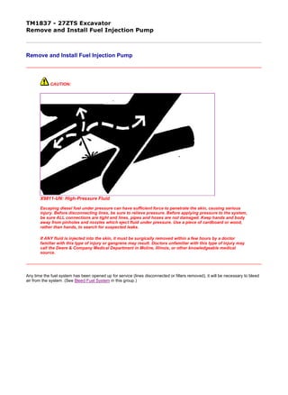
  • 1. TM1837 - 27ZTS Excavator Remove and Install Fuel Injection Pump Remove and Install Fuel Injection Pump CAUTION: X9811-UN: High-Pressure Fluid Escaping diesel fuel under pressure can have sufficient force to penetrate the skin, causing serious injury. Before disconnecting lines, be sure to relieve pressure. Before applying pressure to the system, be sure ALL connections are tight and lines, pipes and hoses are not damaged. Keep hands and body away from pinholes and nozzles which eject fluid under pressure. Use a piece of cardboard or wood, rather than hands, to search for suspected leaks. If ANY fluid is injected into the skin, it must be surgically removed within a few hours by a doctor familiar with this type of injury or gangrene may result. Doctors unfamiliar with this type of injury may call the Deere & Company Medical Department in Moline, Illinois, or other knowledgeable medical source. Any time the fuel system has been opened up for service (lines disconnected or filters removed), it will be necessary to bleed air from the system. (See Bleed Fuel System in this group.) 1/4 2019/11/19 file:///C:/ProgramData/Service%20ADVISOR/Temp/TM1837_09001faa81cb...
  • 2. 1. T123181-UN: Injection Pump Injection and Supply Lines LEGEND: 1 - Injection Line 2 - Cap Screw (4 used) 3 - Hose 4 - Clamp 5 - Washer (8 used) 6 - Supply Line Remove fuel injection line (1). 2. Remove clamp (4) and hose (3). 3. Remove cap screws (2) and washers (5). 4. Remove fuel supply line (6). 5. T122388-UN: Align Fuel Cut-Off Lever-to-Governor Cover LEGEND: 2/4 2019/11/19 file:///C:/ProgramData/Service%20ADVISOR/Temp/TM1837_09001faa81cb...
  • 3. 1 - Pin 2 - Lever 3 - Cover Align hole of fuel cut-off lever (2) with hole of governor cover (3) and insert pin (1) into hole. 6. T122387-UN: Center Control Link Pin Groove LEGEND: 1 - Control Link 2 - Injection Pump Center Position 3 - Pin Check to see if pin groove of control link (1) is at center of injection pump (2). NOTE: Mark each pump to aid in assembly. Do not reuse shim; replace with same thickness. 7. T121823-UN: Remove and Install Injection Pump LEGEND: 3/4 2019/11/19 file:///C:/ProgramData/Service%20ADVISOR/Temp/TM1837_09001faa81cb...
  • 4. 1 - Nut (4 used) 2 - Injection Pump 3 - Shim 4 - Clamp Remove nuts (1), injection pump (2), and shim (3). NOTE: For injection pump repair and testing, have an authorized ADS diesel injection repair station perform the work. Unauthorized repairs made to the fuel injection pump will void warranty. 8. Install new shim (3) with same thickness as removed. 9. Install injection pump (2) making sure that rack pin is in groove of control rack before tightening injection pump. 10. Remove rack pin from fuel cut-off lever. Confirm lever moves smoothly. 11. Install fuel supply line, washers, cap screw and tighten. 12. Install hose and clamp. 13. Install fuel injection line and tighten nut. 14. Bleed fuel system. (See procedure in this group.) Item Measurement Specification Fuel Injection Pump Cap Screw Torque 28 N˙m (252 lb-ft) Item Measurement Specification Fuel Injection Fuel Supply Line Cap Screw Torque 24 N˙m (212 lb-in.) Item Measurement Specification Fuel Injection Line Nut Torque 24 N˙m (212 lb-in.) CED,OUOE003,10023-19-19990818 4/4 2019/11/19 file:///C:/ProgramData/Service%20ADVISOR/Temp/TM1837_09001faa81cb...
  • 5. TM1837 - 27ZTS Excavator Repair Fuel Injection Pump Repair Fuel Injection Pump IMPORTANT: Do not disassemble the fuel injection pump further than necessary for installing available repair parts—not even for cleaning. Be sure that all identification numbers are legible so that pump is set to the correct specification for its intended application. For injection pump repair and testing, have an authorized ADS diesel injection repair station perform the work. Unauthorized repairs made to the fuel injection pumps will void warranty. CED,OUOE003,10024-19-19990818 1/1 2019/11/19 file:///C:/ProgramData/Service%20ADVISOR/Temp/TM1837_09001faa81cb...
  • 6. TM1837 - 27ZTS Excavator Injection Timing Test and Adjustment Injection Timing Test and Adjustment T123182-UN: Remove Valve Holder from Injection Pump LEGEND: 1 - Valve Holder 2 - Spring 3 - Injection Pump 1. Remove fuel injection line from No. 1 cylinder. 2. Remove valve holder (1) from injection pump and remove spring (2). 3. Install valve holder without spring into injection pump (3). 4. Slowly turn crankshaft pulley clockwise. At the same time continue to feed the fuel. Stop turning crankshaft when fuel stops flowing out of No. 1 delivery valve holder. NOTE: This crank angle position is the starting point of injection. 1/2 2019/11/19 file:///C:/ProgramData/Service%20ADVISOR/Temp/TM1837_09001faa81cb...
  • 7. 5. T123169-UN: Groove Mark and TDC Mark LEGEND: 1 - Groove Mark 2 - TDC Mark Note position of groove mark (1) on crankshaft pulley with TDC mark (2) on timing gear case cover. 6. Shim accordingly. Adjust timing with a shim between injection pump and cylinder block. 7. Remove valve holder and install spring. 8. Install valve holder and fuel injection line. Item Measurement Specification Fuel Injection Fuel Injection Pump Timing 19° BTDC CED,OUOE003,21117-19-20000111 2/2 2019/11/19 file:///C:/ProgramData/Service%20ADVISOR/Temp/TM1837_09001faa81cb...
  • 8. TM1837 - 27ZTS Excavator Remove and Install Fuel Injection Nozzle Remove and Install Fuel Injection Nozzle CAUTION: X9811-UN: High-Pressure Fluid Escaping diesel fuel under pressure can have sufficient force to penetrate the skin, causing serious injury. Before disconnecting lines, be sure to relieve pressure. Before applying pressure to the system, be sure ALL connections are tight and lines, pipes and hoses are not damaged. Keep hands and body away from pinholes and nozzles which eject fluid under pressure. Use a piece of cardboard or wood, rather than hands, to search for suspected leaks. If ANY fluid is injected into the skin, it must be surgically removed within a few hours by a doctor familiar with this type of injury or gangrene may result. Doctors unfamiliar with this type of injury may call the Deere & Company Medical Department in Moline, Illinois, or other knowledgeable medical source. Any time the fuel system has been opened up for service (lines disconnected or filters removed), it will be necessary to bleed air from the system. (See Bleed Fuel System in this group.) IMPORTANT: Before removal, thoroughly remove all dirt from the cylinder head around fuel injection nozzles. Clean with compressed air to prevent dirt from entering the cylinders. Plug the bore in the cylinder head after each nozzle has been removed. Cap fuel line openings as soon as they are disconnected. Do not bend the fuel delivery lines, as this may affect their durability. When loosening the fuel pressure lines, hold male union of nozzle line stationary with a backup wrench. 1/3 2019/11/19 file:///C:/ProgramData/Service%20ADVISOR/Temp/TM1837_09001faa81cb...
  • 9. 1. T123164-UN: Remove Fuel Injection and Leak-Off Line LEGEND: 1 - Fuel Injection Line (3 used) 2 - Nut (3 used) 3 - Nozzle (3 used) 4 - Washer (3 used) 5 - Fuel Leak-Off Line Remove fuel injection line (1) from fuel injection nozzle and fuel injection pump using a backup wrench on nozzle connection. NOTE: When all fuel injection nozzles have been removed, disconnect leak-off line and remove as a complete assembly. For individual nozzle removal, remove only the section of leak-off line necessary for nozzle removal. 2. Remove nut (2) to remove fuel leak-off line (5). Line must be removed as an assembly. Remove washer (4). 3. Remove fuel injection nozzle (3). Protect opening to avoid contamination. 4. Repair or replace as necessary. 5. IMPORTANT: Before installing injection nozzles, make sure nozzles are clean and free from oil or grease. NOTE: If nozzle bore in cylinder head must be cleaned, use a nozzle bore cleaning tool. Install injection nozzles (3) and tighten. 6. Install washer (4) and leak-off line (5). Tighten nut (2). Item Measurement Specification Fuel Injection Nozzle-to-Cylinder Head Nut Torque 49 N˙m (36 lb-ft) Item Measurement Specification Fuel Injection Leak-Off Line Nut Torque 34 N˙m (301 lb-in.) 2/3 2019/11/19 file:///C:/ProgramData/Service%20ADVISOR/Temp/TM1837_09001faa81cb...
  • 10. 7. Install fuel injection line (1) using a backup wrench on nozzle connection. 8. Bleed fuel system. (See procedure in this group.) Item Measurement Specification Fuel Injection Line Nut Torque 24 N˙m (212 lb-in.) CED,OUOE003,21174-19-20000118 3/3 2019/11/19 file:///C:/ProgramData/Service%20ADVISOR/Temp/TM1837_09001faa81cb...
  • 11. TM1837 - 27ZTS Excavator Disassemble and Assemble Fuel Injection Nozzle Disassemble and Assemble Fuel Injection Nozzle T123165-UN: Fuel Injection Nozzle LEGEND: 1 - Retaining Nut 2 - Injection Nozzle 3 - Spring Spacer 4 - Push Rod 5 - Nozzle Assembly 6 - Shim 7 - Shim 8 - Nozzle Spring 1. Disassemble parts (1—8). 1/5 2019/11/19 file:///C:/ProgramData/Service%20ADVISOR/Temp/TM1837_09001faa81cb...
  • 12. 2. T113929-UN: Check Valve Fit in Body Remove nozzle assembly from nozzle body. Keep parts separate to maintain proper needle valve-to-body combination. 3. Check to see if valve moves smoothly in body. If not, repair or replace nozzle. 4. T113930-UN: Push Rod Spring Check push rod spring for wear, weakness, and corrosion. 2/5 2019/11/19 file:///C:/ProgramData/Service%20ADVISOR/Temp/TM1837_09001faa81cb...
  • 13. 5. T113931-UN: Nozzle Holder Push Rod/Needle Valve Check nozzle holder push rod curvature. 6. Check nozzle holder push rod and needle valve contact surfaces for excessive wear and poor contact. 7. T123166-UN: Injection Nozzle Check injection nozzle needle valve, valve seat and injection nozzle hole for carbon deposits. If carbon deposits are present, replace injection nozzle and needle valve. 8. Hold nozzle body vertically. Pull needle valve out about one-third away from nozzle body. Release needle valve. Check that needle valve falls back into nozzle body as far as valve seat. If needle valve does not fall back into nozzle body as far as valve seat, replace injection nozzle and needle valve. 9. NOTE: 3/5 2019/11/19 file:///C:/ProgramData/Service%20ADVISOR/Temp/TM1837_09001faa81cb...
  • 14. There must be no oil on the contact surfaces of the injection nozzle and the injection nozzle holder. Clean these contact surfaces with diesel fuel before installation. The nozzle dowel pin must be aligned with the dowel hole in nozzle holder body. T113937-UN: Align Nozzle Dowel Pin to Holder Body Install injection nozzle. 10. Install nozzle holder push rod, push rod spring, and nozzle adjusting screw. 11. T123168-UN: Adjust Pressure Adjust injection starting pressure using 5-8840-9016-0 nozzle tester with shims. Item Measurement Specification Fuel Injection Nozzle Starting Pressure 13 238 kPa (1920 psi) (132 bar) 4/5 2019/11/19 file:///C:/ProgramData/Service%20ADVISOR/Temp/TM1837_09001faa81cb...
  • 15. 12. T123167-19: Injector Nozzle Spray Conditions Check spray condition of injection nozzle. CED,OUOE003,10027-19-20000111 5/5 2019/11/19 file:///C:/ProgramData/Service%20ADVISOR/Temp/TM1837_09001faa81cb...
  • 16. TM1837 - 27ZTS Excavator Bleed Fuel System Bleed Fuel System Turn starter switch to the on position. This will allow the fuel pump to force feed fuel to the fuel pipe and the lead-off pipe. Air in the fuel system is automatically bled. CED,OUOE003,10028-19-19990818 1/1 2019/11/19 file:///C:/ProgramData/Service%20ADVISOR/Temp/TM1837_09001faa81cb...
  • 17. TM1837 - 27ZTS Excavator Engine Valve Clearance Adjustment Engine Valve Clearance Adjustment Summary 1. Perform measurement when engine is cold. 2. Before starting work, clean head cover mounting area to avoid contamination in engine. Preparation 1. T123169-UN: Align TDC Mark on Crankshaft Pulley LEGEND: 1 - TDC Mark 2 - Pointer Locate top dead center (TDC) in compression stroke. Align TDC (top dead center) mark (1) on crankshaft pulley with pointer (2) located on timing gear case as illustrated. Piston No. 1 or piston No. 3 is now positioned at the TDC in its compression stroke. 2. Remove head cover. 3. Check for play in the No. 1 intake and exhaust valve rocker arms. If the No. 1 cylinder intake and exhaust valve rocker arms have play, No. 1 piston is at TDC on the compression stroke. If the No. 1 cylinder intake and exhaust valve rocker arms are depressed, the No. 3 piston is at TDC on the compression stroke. 4. Start measurement from cylinder (No. 1 or No. 3) positioned at TDC in compression stroke. Measurement 1/3 2019/11/19 file:///C:/ProgramData/Service%20ADVISOR/Temp/TM1837_09001faa81cb...
  • 18. T112872-UN: Measure Rocker Arm-to-Valve Stem Clearance 1. Insert a feeler gauge into clearance between rocker arm and valve stem end to measure valve clearance. NOTE: The cylinders are aligned from No. 1 to No. 3 in order, as viewed from the fan side. 2. T127228-19: Valve Arrangement Adjust the circle or double circle marked valves as shown, while the No. 1 or No. 3 cylinder is at TDC on compression stroke. 3. Rotate crankshaft 360°. Align TDC mark with pointer. Then, continue measurement of other valves in same way. Evaluation Standard Valve Clearance: Item Measurement Specification Engine Valve Clearance Adjustment 2/3 2019/11/19 file:///C:/ProgramData/Service%20ADVISOR/Temp/TM1837_09001faa81cb...
  • 19. Place the No. 1 or No. 3 cylinder at TDC by turning the crankshaft until the TDC mark on the front cover aligns with the groove mark on the crankshaft pulley. NOTE: If the No. 1 cylinder intake and exhaust valve rocker arms have play, the No. 1 piston is at TDC on the compression stroke. If the No. 1 cylinder intake and exhaust valve rocker arms are depressed, the No. 3 piston is at TDC on the compression stroke. Adjustment T112872-UN: Measure Rocker Arm-to-Valve Stem Clearance If the measurement results are out of specification, adjust the valve clearance in the same order of measurement. 1. Loosen adjusting screw lock nuts for rocker arms. 2. Insert thickness gauge set at 0.20 mm (0.008 in.). Adjust adjusting screws until slight drag can be felt on thickness gauge. 3. Tighten lock nuts securely. 4. Check valve clearance again after lock nuts are tightened. Engine Intake and Exhaust Standard Valve Clearance 0.20 ± 0.05 mm (0.008 ± 0.002 in.) with engine cold Item Measurement Specification Engine Valve Clearance Adjustment Engine Intake and Exhaust Standard Valve Clearance 0.20 ± 0.05 mm (0.008 ± 0.002 in.) with engine cold CED,OUOE003,21120-19-20000111 3/3 2019/11/19 file:///C:/ProgramData/Service%20ADVISOR/Temp/TM1837_09001faa81cb...
  • 20. Thank you very much for your reading. Please Click Here. Then Get COMPLETE MANUAL. NO WAITING NOTE: If there is no response to click on the link above, please download the PDF document first and then click on it.
  • 21. TM1837 - 27ZTS Excavator Remove and Install Starter Remove and Install Starter T125137-UN: Starter LEGEND: 1 - Electrical Connector 2 - Nut 3 - Cap Screw 4 - Nut IMPORTANT: Always disconnect the negative (-) battery cables before removing starter or a short circuit could result. 1. Disconnect negative (-) battery cables. 2. Remove seat. (See procedure in Group 1821.) 3. Remove seat base. (See procedure in Group 1821.) 4. Disconnect electrical connector (1). 5. Remove nut (4). Remove battery cable. 1/2 2019/11/19 file:///C:/ProgramData/Service%20ADVISOR/Temp/TM1837_09001faa81cb...
  • 22. 6. Remove cap screw (3). 7. Remove nut (2). Remove starter. 8. Replace parts as necessary. 9. Install starter. Tighten cap screw (3). 10. Connect wiring leads. 11. Connect negative (-) battery cables. Item Measurement Specification Starter Starter-to-Flywheel Housing Cap Screw Torque 13 N˙m (115 lb-in.) CED,OUOE003,21121-19-20000111 2/2 2019/11/19 file:///C:/ProgramData/Service%20ADVISOR/Temp/TM1837_09001faa81cb...