This document provides a maintenance schedule for an MX Magnum tractor. It lists maintenance tasks to perform at regular intervals such as every 10 hours, 50 hours, 100 hours, etc. as well as tasks to perform when warning messages display. The schedule includes checking, greasing, changing and cleaning components like the air cleaner, engine oil, transmission oil, coolant, filters, hoses, belts, and making adjustments to valves. Footnotes provide additional details for some items.
1. Rac 6-12723 � 2005 1 Issued 10-02 (Revised 08-05)
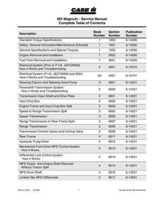
MX Magnum - Service Manual
Complete Table of Contents
Description
Book
Number
Section
Number
Publication
Number
Standard Torque Specifications 1 1000 6-14200
Safety, General Information/Maintenance Schedule 1 1001 6-14200
General Specifications and Special Torques 1 1002 6-14200
Engine Removal and Installation 1 2002 6-14200
Fuel Tank Removal and Installation 1 3001 6-14200
Electrical System (Prior to P.I.N. JAZ129933)
How it Works and Troubleshooting
2 4001 6-14210
Electrical System (P.I.N. JAZ129933 and After)
How it Works and Troubleshooting
2A 4001 6-12741
Steering Column and Steering Hand Pump 3 5001 6-14221
Powershift Transmission System
How it Works and Troubleshooting
3 6000 6-14221
Transmission Input Shaft and Drive Plate 3 6001 6-14221
Input Drop Box 3 6002 6-14221
Engine Frame and Input Drop Box Split 3 6003 6-14221
Speed to Range Transmission Split 3 6005 6-14221
Speed Transmission 3 6006 6-14221
Range Transmission to Rear Frame Split 3 6007 6-14221
Range Transmission 3 6008 6-14221
Transmission Control Valves and Inching Valve 3 6009 6-14221
Rear Frame 4 6011 6-14231
Hydraulic Pump Drive 4 6012 6-14231
Mechanical Front Drive MFD Control System
How it Works
4 6013 6-14231
Differential Lock Control System
How it Works
4 6014 6-14231
MFD Clutch And Output Shaft Removal
Without Tractor Split
4 6015 6-14231
MFD Drive Shaft 4 6016 6-14231
Limited Slip MFD Differential 4 6017 6-14231
2. MX Magnum MX210, MX230, MX255, MX285
Rac 6-12723 � 2005 2 Issued 10-02 (Revised 08-05)
Locking MFD Differential 4 6018 6-14231
Rear Axle and Planetaries 4 6019 6-14231
Power Take Off Control System How it Works 4 6020 6-14231
MFD Planetary Hub, Steering Knuckle, and Axle
Drive Shaft
4 6022 6-14231
Suspension MFD Axle 4 6023 6-14231
Suspended MFD Axle System
How It Works and Troubleshooting
4 6024 6-14231
Brake Valve 4 7001 6-14231
Brake Cylinders 4 7002 6-14231
Park Brake 4 7004 6-14231
Trailer Brake System - How It Works 4 7005 6-14231
PTO Assembly - Single and Dual Speeds 4A 6021 7-86731
PTO Clutch Assembly
Single and Reversible Single Speeds
4A 6025 6-17540
How to Read Symbols in a Hydraulic Schematic 5 8000 6-14241
Hydraulic System
How it Works with Troubleshooting
5 8001 6-14241
PTO and Differential Lock Valve 5 8002 6-14241
Remote Valve and Coupler Service 5 8003 6-14241
Remote Hydraulic System
How it Works and Troubleshooting
5 8004 6-14241
Priority and Regulator Valve 5 8005 6-14241
Charge Pump 5 8006 6-14241
PFC Piston Pump and Hydraulic Filter 5 8007 6-14241
Hitch System - How it Works 5 8008 6-14241
Hitch Control Valve 5 8009 6-14241
Pedal & Pedal Switch Adjustments 5 9001 6-14241
Cab Raise/Removal and Installation 5 9005 6-14241
Tilt And Fixed Hoods, A/C Condenser, Radiator, And
Air-To-Air Aftercooler
5 9008 6-14241
Description
Book
Number
Section
Number
Publication
Number
3. MX Magnum MX210, MX230, MX255, MX285
Rac 6-12723 � 2005 3 Issued 10-02 (Revised 08-05)
Air Conditioning Troubleshooting 5 9010 6-14241
Air Conditioner System Service 5 9020 6-14241
Viscous Fan Drive Test 5 9030 6-14241
Standard Instrumentation
Programming and Fault Codes
6 10001 6-14250
Hitch Controller
Calibration and Fault Codes
6 10002 6-14250
Transmission Controller
(With Suspended Axle) Calibration and Fault Codes
6 10003 6-14250
Armrest Controller
Calibration and Fault Codes
7 10004 6-14260
Remote Hydraulics Controller
Calibration and Fault Codes
7 10005 6-14260
PTO Controller Configuration and Fault Codes 7 10006 6-14260
Performance Monitor Controller Fault Codes 7 10008 6-14260
Instrument Cluster (ICU2)
Programming and Fault Codes
8 10009 6-17550
Description
Book
Number
Section
Number
Publication
Number
4. MX Magnum MX210, MX230, MX255, MX285
Rac 6-12723 � 2005 4 Issued 10-02 (Revised 08-05)
Service Information Packaged with 6-12722
Electrical Schematic (Prior to P.I.N. JAZ129933). . . . . . . . . . 6-12750
Electrical Schematic (P.I.N. JAZ129933 and After) . . . . . . . . . 6-17260
Hydraulic Schematic . . . . . . . . . . . . . . . . . . . . . . . . . . . . . . . . 6-12830
Loctite Product Chart . . . . . . . . . . . . . . . . . . . . . . . . . . . . . . . . 8-98902
A/C Temperature Poster. . . . . . . . . . . . . . . . . . . . . . . . . . . . . . 6-13060
Service Information Not Packaged with 6-12723 But Required for Engine Repair
Electronic 8.3L Engine for MX255 and MX285 Manual Numbers 7-88622 and 7-88631
Mechanical 8.3L Engine for MX210 and MX230 Manual Number 7-65440
5. Section
1001
1001
CASE CORPORATION
700 State Street
Racine, WI 53404 U.S.A. Rac 6-13960
� 2002 Case Corporation
Printed in U.S.A.
November, 2002
SAFETY, GENERAL INFORMATION / MAINTENANCE
SCHEDULE
6. 1001-3
Rac 6-13960 Issued 11-02 Printed in U.S.A.
Template Name: SM_2_col
Template Date: 1994_04_05
Alt= to hide template information
Alt+ to display template information
SAFETY
THIS SAFETY ALERT SYMBOL INDICATES IMPORTANT
SAFETY MESSAGES IN THIS MANUAL. WHEN YOU SEE
THIS SYMBOL, CAREFULLY READ THE MESSAGE THAT
FOLLOWS AND BE ALERT TO THE POSSIBILITY OF
PERSONAL INJURY OR DEATH. M171B
To prevent injury always follow the Warning, Caution and
Danger notes in this section and throughout the manual.
Put the warning tag shown below on the key for the key switch
when servicing or repairing the machine. One warning tag is
supplied with each machine. Additional tags are available
from your service parts supplier.
Before servicing a machine, park the machine on hard level
ground. Turn off the engine, apply the parking brake and
remove the key from the key switch. Put blocks in front of and
behind either the front or rear wheels.
WARNING: Read the operators manual to
familiarize yourself with the correct control
functions. M489
WARNING: Operate the machine and
equipment controls from the seat position
only. Any other method could result in
serious injury. M490
WARNING: This is one man machine, no
riders allowed. M491
201L95
!
!
!
WARNING: Before starting engine study
Operators Manual safety messages. Read
all safety signs on machine. Clear the area of
other persons. Learn and practice safe use
of controls before operating. It is your
responsibility to understand and follow
manufacturers instructions on machine
operation, service, and to observe pertinent
laws and regulations. Operator and Service
Manuals may be obtained from your
equipment dealer. M103A
WARNING: If you wear clothing that is too
loose or do not use the correct safety
equipment for your job, you can be injured.
Always wear clothing that will not catch on
objects. Extra safety equipment that can be
required includes hard hat, safety shoes, ear
protection, eye or face protection, heavy
gloves and reflector clothing. M492
WARNING: When working in the area of the
fan belt with the engine running, avoid loose
clothing if possible, and use extreme caution.
M493
WARNING: When doing checks and tests
on the equipment hydraulics, follow the
procedures as they are written. DO NOT
change the procedure. M494
WARNING: When putting the hydraulic
cylinders on this machine through the
necessary cycles to check operation or to
remove air from a circuit, make sure all
people are out of the way. M495
!
!
!
!
!
7. 1001-4
Rac 6-13960 Issued 11-02 Printed in U.S.A.
Template Name: SM_2_col
Template Date: 1994_04_05
Alt= to hide template information
Alt+ to display template information
WARNING: Always wear heat protective
gloves to prevent burning your hands when
handling heated parts. SM121A
WARNING: Lower all attachments to the
ground or use stands to safely support the
attachments before you do any maintenance
or service. M496
WARNING: Hydraulic oil or diesel fuel
leaking under pressure can penetrate the
skin and cause infection or other injury.
To Prevent Personal Injury:
Relieve all pressure, before disconnecting
fluid lines. Before applying pressure, make
sure all connections are tight and
components are in good condition.
Never use your hand to check for suspected
leaks under pressure.
Use a piece of cardboard or wood for this
purpose. If injured by leaking fluid, see your
doctor immediately. SM171A
WARNING: When removing hardened pins
such as a pivot pin, or a hardened shaft, use
a soft head (brass or bronze) hammer or use
a driver made from brass or bronze and a
steel head hammer. M497
WARNING: When using a hammer to
remove and install pivot pins or separate
parts using compressed air or using a
grinder, wear eye protection that completely
encloses the eyes (approved goggles or
other approved eye protectors). M498
WARNING: Use suitable floor (service)
jacks or chain hoist to raise wheels or tracks
off the floor. Always block machine in placed
with suitable safety stands. M499
!
!
!
!
!
!
WARNING: When servicing or repairing the
machine. Keep the shop floor and operators
compartment and steps free of oil, water,
grease, tools, etc. Use an oil absorbing
material and or shop cloths as required. Use
safe practices at all times. M500
WARNING: Some components of this
machine are very heavy. Use suitable lifting
equipment or additional help as instructed in
the Service Manual. M501
WARNING: Engine exhaust fumes can
cause death. If it is necessary to start the
engine in a closed place, remove the exhaust
fumes from the area with an exhaust pipe
extension. Open the door and get outside air
into the area. M502
WARNING: When the battery electrolyte is
frozen, the battery can explode if (1), you try
to charge the battery, or (2), you try to jump
start and run the engine. To prevent the
battery electrolyte from freezing, try to keep
the battery at full charge. If you do not follow
these instructions, you or others in the area
can be injured. M503
WARNING: Batteries contain acid and
explosive gas. Explosions can result from
sparks, flames or wrong cable connections.
To connect the jumper cables correctly to the
battery of this machine see the Operators
Manual. Failure to follow these instructions
can cause serious injury or death. M504
!
!
!
!
!
8. 1001-5
Rac 6-13960 Issued 11-02 Printed in U.S.A.
Template Name: SM_2_col
Template Date: 1994_04_05
Alt= to hide template information
Alt+ to display template information
GENERAL INFORMATION
Cleaning
Clean all metal parts except bearings, in mineral spirits or by
steam cleaning. Do not use caustic soda for steam cleaning.
After cleaning, dry and put oil on all parts. Clean oil passages
with compressed air.
Inspection
Check all parts when the parts are disassembled. Replace all
parts that have excessive wear or are damaged. Small
scoring or grooves can be removed with a hone or crocus
cloth. Complete visual inspection for indications of wear,
pitting and the replacement of parts necessary will prevent
early failures.
Bearings
Clean bearings with a good clean solvent and permit to air
dry. DO NOT DRY BEARINGS WITH COMPRESSED AIR.
Check bearings for smooth easy action. If the bearing has a
loose fit or rough action, the bearing must be replaced.
Needle Bearings
Before you press needle bearings into a bore, always remove
any metal protrusions in the bore or the edge of the bore.
Before you press bearings into position, put petroleum jelly
on the inside and outside diameter of the bearing.
Gears
Check all gears for excessive wear or damage. Replace gears
as necessary.
Oil Seals, O-rings and Gaskets
Always install new oil seals, O-rings and gaskets. Put
petroleum jelly on seals and O-rings.
Shafts
Check all shafts for excessive wear or damage. Check the
bearing and oil seal surfaces on the shafts for excessive wear
or damage. Replace shafts as necessary.
Service Parts
Always install genuine Case service parts. When ordering
refer to the Parts Catalog for the correct part number of the
genuine Case replacement items. Failures due to the use of
other than genuine Case replacement parts are not covered
by warranty.
Lubrication
Use only the oils and lubrication specified in the Operators or
Service Manual. Failures due to the use of non specified oils
and lubricants are not covered by warranty.
9. 1001-6
Rac 6-13960 Issued 11-02 Printed in U.S.A.
Template Name: SM_2_col
Template Date: 1994_04_05
Alt= to hide template information
Alt+ to display template information
MAINTENANCE SCHEDULE
Note A -In severe or wet conditions, Interval is every 10 hours or daily.
Note B - Perform initial service in first 50 hours of operation.
Service Interval Maintenance Requirement Check Grease Change Clean
When Warning
Message Displays
Air Cleaner Element X
Every 10 Hours Or Daily
Engine Oil Level X
Engine Coolant Level X
Transmission Oil Level X
Every 50 Hours Engine Primary Fuel Filter - Drain Water
Every 100 Hours Front Hitch (If Equipped) X
Every 300 Hours
Battery Water Level X
Engine Air Intake Hoses X
Engine Coolant Level-Deaeration Tank X
*Engine Oil And Filter X
Front And Rear Wheel Bolt Torques X
Front Axle And Rear Hitch (Note A) X
Fuel Tank - Drain Water
Differential And Planetary Oil Level (Note B) X
Every 600 Hours
Engine Coolant Antifreeze Protection X
Engine Coolant Filter X
Engine Coolant Hoses And Clamps X
Engine Fuel Filters X
Changeable PTO Internal Splines X
Every 1200 Hours Or
Annually
Engine Primary And Secondary Air Filter X
Engine Air Precleaner X
Differential and Planetary Oil X
Every 1200 Hours Engine Valve Adjustment (Model 210 & 230)
(Note C)
X
Every 1500 Hours Transmission Oil, Filter(s) and Breather X
Every 2400 Hours
Engine Coolant And Coolant Conditioner X
Engine Fuel Injection Nozzles and Pump See
(Note C)
X
Engine Crankshaft Dampener (Note C) X
As Required
Cab Air And Recirculation Filters X X
Cab Air Filter Dust Valve X
Engine Primary Air Filter X
Grill Screens, Radiator, Condenser/Fuel Cooler,
Oil Cooler, Air to Air Cooler
X
Serpentine Belt X
Tire Pressure X
11. 4
Rac 6-13130 Issued 10-02
ENGINE REMOVAL
STEP 1
96R-28A
Park the tractor on a hard, level surface. Put the
transmission shift lever in PARK. Turn off the engine
and remove the key. Place blocks in front of and
behind the rear wheels. Drain the radiator coolant
into a suitable, clean container.
STEP 2
RD02E069
Remove the toolbox and battery cover. Disconnect
the negative (-) battery cable. Disconnect the positive
(+) battery cable.
STEP 3
RD02E060
Lift up and remove the air cleaner door from the left
side of the tractor. Remove the front windshield
washer hose (1) from the nozzle on the fixed hood.
Remove the four nuts (2) and lift the fixed hood from
the right side of the tractor.
STEP 4
RD02F129
Remove the left lower fixed hood panel.
WARNING: Check and service cooling
system according to maintenance
instructions. Hot coolant can spray out if the
deaeration tank cap is removed while system
is hot. To remove the adoration tank cap, let
system cool, turn to the first notch, then wait
until all the pressure is released. Scalding
can result from the fast removal of the
adoration tank cap. M855
!
12
12. 5
Rac 6-13130 Issued 10-02
STEP 5
RD02F134
Disconnect the main wiring harness connector.
STEP 6
RD02F130
Tag and disconnect the electrical plugs from the fuse
box. Remove the electrical plug for the tilt hood front
lamps. Remove the tilt hood. Refer to Section 9008 in
this service manual for the procedure.
STEP 7
RD02F132
Remove the passive terminator harness.
STEP 8
RD02F131
Remove the starter solenoid from the hood support.
STEP 9
RD02F133
Remove the windshield washer reservoir electrical
connectors.
13. 6
Rac 6-13130 Issued 10-02
STEP 10
2-14
RD02F146
On electronic injection pump models, remove the fuel
supply line (1) and the return line (2). Disconnect the
electronic injection pump wiring harness connector
(3).
STEP 11
RD02F141
RD02F175
On mechanical injection pump models, remove the
optional foot throttle cable (1), if equipped, the hand
throttle cable (2), the fuel supply line (3), and the
engine wiring harness connector (4).
STEP 12
RD02F150
Disconnect the ether start tube from the intake
manifold on the left side of the engine.
1
2
3
1
2
3
4
14. 7
Rac 6-13130 Issued 10-02
STEP 13
RD02F143
Disconnect the electrical connectors from the air filter
sensor (1) on the air cleaner outlet tube. Disconnect
the electrical plug (2) for the intake manifold
temperature sensor. Remove the three harness and
hose retainers (3) on the left side of the engine.
STEP 14
RD02F152
Remove the left and right fan shields by removing the
bolt (1) and pulling out on the shield.
STEP 15
RD02F137
Remove the air cleaner outlet tube at the
turbocharger elbow clamp (1). Loosen and remove
the turbocharger elbow at the turbo clamp (2).
Loosen the clamp (3) at the turbo outlet pipe.
STEP 16
RD02F144
RD02F157
Remove the upper hose clamps (1) at the air-to-air
aftercooler. Remove the hose clamps (2) from the
aftercooler tubes to the intake manifold and the turbo.
Remove the aftercooler tubes. Tag and remove the
three hoses (3) from the deaeration tank. Remove
the air cleaner outlet tube (4) at the air cleaner rubber
elbow clamp.
STEP 17
RD02F151
Trace the line back to the injection pump, so the
correct line is removed. Disconnect the fuel return
line from the fuel injection pump at the fuel cooler.
1
2
3
1
1
3 2
1 1
3
2
24
15. 8
Rac 6-13130 Issued 10-02
STEP 18
RD02F153
Tag and remove the two wires (1) from the back of
the alternator and the battery cable. Remove the
upper radiator hose at the clamp (2).
STEP 19
RD02F171
Remove the lower radiator hose at the hose clamp
(1). Remove the heater return hose at the hose
clamp (2).
STEP 20
RD02F173
Hold the shaft (1) of the fan hub on the two flat areas.
Remove the fan blade and fan drive by loosening the
viscous fan drive adapter (2).
IMPORTANT: The viscous fan drive adapter has a
left-hand thread. Loosen by turning clockwise.
STEP 21
RD02F170
Disconnect the two electrical connectors from the air
conditioning compressor high pressure switch (1)
and the clutch. Remove the engine fan belt (2).
Remove the three air conditioning compressor
mounting bolts (3).
2
1
1
2
2
1
3
2
1
16. 9
Rac 6-13130 Issued 10-02
STEP 22
RD02F156
Move the air conditioning compressor to the left side
of the tractor, with the hoses attached. Securely
support the compressor.
STEP 23
RD02F139
Remove the aspirator tube hose (1) at the exhaust
elbow. Loosen the lower clamp (2) on the exhaust
flex pipe.
STEP 24
RD02F138
Remove the fixed hood support bolts (1) from both
sides of the tractor. Properly support the air cleaner
assembly and the hood support and remove from the
tractor. Remove the turbo outlet pipe.
STEP 25
RD02F172
Remove the heater supply hose (1) from the fitting on
the engine block. Remove the cables from the starter
terminal (2). Remove the harness and hose retainer
attached to the flywheel shield behind the engine
block. Move the harnesses and hoses out of the way
1
2
1
1
2
1
17. 10
Rac 6-13130 Issued 10-02
STEP 26
RD02F140
Remove the five bolts (1) for the left-hand hood
support bracket. Remove the four bolts for the right-
hand hood support bracket, along with the engine to
frame ground strap. Remove the brackets.
STEP 27
2-2
Remove the oil cooler supply tube (1) and the oil
cooler return tube (2).
STEP 28
RD02F174
Remove the drive shaft shield (1) and the flywheel
shield (2). Refer to Section 6001, Transmission Input
Shaft and Drive Plate, for the procedure.
STEP 29
RD02F176
Make an alignment mark on the end of the drive shaft
connected to the engine for installation. Remove the
four bolts attaching the front universal joint to the
drive plate. Slide the drive shaft back.
1
1
1
2
1
12
18. 11
Rac 6-13130 Issued 10-02
STEP 30
4-12
Attach suitable lifting equipment to the front and rear
engine lifting brackets. Put a small amount of tension
on the hoist.
STEP 31
RI01H053
Remove the two front engine mount clamp bolts.
Remove the clamp.
STEP 32
4-14
Remove the engine.
NOTE: Make sure all electrical wires and hoses are
disconnected before removing the engine.
STEP 33
RI01H055
RI01H052
Inspect the front engine mount support and the iso-
mount for damage or wear. Replace, if necessary.
STEP 34
4-23CR1
Inspect the two engine rear rubber mounts for
damage or wear. Replace, if necessary.
19. 12
Rac 6-13130 Issued 10-02
ENGINE INSTALLATION
STEP 35
RI01H052
4-23CR1
If removed, assemble the front engine iso-mount and
install the rear engine rubber mounts. Tighten the
front iso-mount thru bolt to a torque of 160 to 220 Nm
(118 to 162 lb ft).
STEP 36
RI01H055
If removed, install the front engine mount support
and the iso-mount. Tighten the front engine mount
support bolts to a torque of 101 to 113 Nm (75 to 83
lb ft).
STEP 37
4-14
Properly support the engine. Install the engine into
the tractor chassis.
NOTE: Make sure all electrical wires and hoses will
not be pinched or binding when installing the engine.
STEP 38
RI01H053
Install the two front engine mount clamp bolts. Keep
tension on the lifting equipment until these bolts are
installed. Relieve the tension on the lifting equipment.
Tighten the bolts to a torque of 59 to 106 Nm (44 to
78 lb ft).
20. 13
Rac 6-13130 Issued 10-02
STEP 39
RD02F176
Using the alignment mark made during the removal,
pull the drive shaft forward and install the drive shaft
to the drive plate. Tighten the drive shaft yoke bolts to
a torque of 58 to 64 Nm (43 to 47 lb ft) for the MX210
and the MX230, 101 to 113 Nm (75 to 83 lb ft) for the
MX255 and the MX285. Tighten the bolts in a
crossing pattern.
NOTE: Use a rubber mallet to lightly tap the outside
edge of the top bearing end cap to position it into the
keyway of the yoke. Do not use the bolts to pull the
bearing end caps into the yoke keyway.
STEP 40
RD02F174
Install the drive shaft shield (1) and flywheel shield
(2). Refer to Section 6001 in this manual,
Transmission Input Shaft and Drive Plate, for the
procedure.
STEP 41
2-2
Install the oil cooler supply tube (1) and the oil cooler
return tube (2).
STEP 42
RD02F140
Install the two bolts (1) for the left-hand hood support
bracket. Install the two bolts (2) for the flywheel
shield. Install the bolt (3) for the oil cooler tube clamp.
Install the four bolts for the right-hand hood support
bracket, along with the engine to frame ground strap.
2 1
1
2
1
1
2
3
21. 14
Rac 6-13130 Issued 10-02
STEP 43
RD02F172
Install the heater supply hose (1) on the engine block
fitting. Install the cables on the starter terminal (2).
Install the harness and hose retainer attached to the
flywheel shield, behind the engine block. Route the
harnesses and hoses as shown.
STEP 44
RD02F138
Install the turbo outlet pipe. Slightly tighten the clamp
at the turbo.Properly support the air cleaner
assembly and the hood support and lower into
position. Install the fixed hood support bolts (1) on
both sides of the tractor.
STEP 45
RD02F139
Install the aspirator tube hose clamp (1) at the
exhaust elbow. Tighten the exhaust flex pipe lower
clamp (2).
STEP 46
RD02F170
Position the compressor and hoses on the engine.
Install the three air conditioning compressor
mounting bolts (1) along with the ground wire
terminal (2). Install the engine fan belt. Connect the
two electrical connectors leading to the air
conditioning compressor high pressure switch and
the clutch.
1
2
1
1
1
2
1
2
22. 15
Rac 6-13130 Issued 10-02
STEP 47
RD02F173
Hold the shaft (1) of the fan hub on the two flat areas.
Install the fan blade and fan drive by tightening the
viscous fan drive adapter (2).
IMPORTANT: The viscous fan drive adapter has a
left-hand thread. Tighten by turning
counterclockwise. Do not over tighten the viscous fan
drive adapter on installation.
STEP 48
RD02F171
Install the lower radiator hose at the hose clamp (1).
Install the heater return hose at the hose clamp (2).
STEP 49
RD02F153
Install the two wires on the back of the alternator (1),
and the battery cable. Install the upper radiator hose
at the hose clamp (2).
STEP 50
RD02F151
Connect the fuel return line from the fuel injection
pump to the fuel cooler.
2
1
1
2
2
1
23. 16
Rac 6-13130 Issued 10-02
STEP 51
RD02F157
RD02F144
Install the three hoses (1) at the deaeration tank.
Install the aftercooler tubes at the intake manifold
and the turbo at the hose clamps (2). Install the air
cleaner outlet tube (3) at the air cleaner clamp. Install
the aftercooler tube upper hose clamps (4) at the air-
to-air aftercooler.
STEP 52
RD02F137
Install the turbocharger elbow at the turbo clamp (1).
Install the air cleaner outlet tube at the turbocharger
elbow clamp (2). Tighten the clamp (3) at the turbo
outlet pipe.
STEP 53
RD02F143
Install the three harness and hose retainers (1) on
the left side of the engine. Install the electrical plug
for the intake manifold temperature sensor (2). Install
the electrical connectors at the air filter sensor (3) on
the air cleaner outlet tube.
STEP 54
RD02F150
Connect the ether start tube to the intake manifold on
the left side of the engine.
1
2
23
4 4
2
3 1
3
2
1
24. 17
Rac 6-13130 Issued 10-02
STEP 55
RD02F141
RD02F175
On mechanical injection pump models, install the
optional foot throttle cable (1), if equipped, the hand
throttle cable (2), the fuel supply line (3), and the
engine wiring harness connector (4).
STEP 56
2-14
RD02F146
On electronic injection pump models, install the fuel
supply line (1) and the return line (2). Connect the
electronic injection pump wiring harness at the
connector (3).
STEP 57
RD02F133
Install the windshield washer reservoir electrical
connectors.
1
2
3
4
1
2
3
25. 18
Rac 6-13130 Issued 10-02
STEP 58
RD02F131
Install the starter solenoid on the hood support.
STEP 59
RD02F132
Connect the passive terminator harness.
STEP 60
RD02F134
Connect the main wiring harness connector (1).
Connect the remaining electrical plugs at the fuse
box (2).
STEP 61
Close the petcock on the hose located under the
tractor radiator. Check and replace all filters, as
required. Fill the cooling system. Check the coolant
level at the coolant reservoir and the deaeration tank.
Check all fluid levels before starting the engine. Make
sure the transmission shift lever is in PARK. Start the
engine briefly. Shut the engine off and recheck all
connections and fluid levels. Restart and run the
engine. Turn the engine off and remove the key.
STEP 62
RD02F130
Install the tilt hood. Refer to Section 9008 for the
procedure. Connect the electrical plug for the tilt
hood front lamps.
STEP 63
RD02F152
Install the left and right fan shields and tighten the
bolt (1).
1
2
1
26. 19
Rac 6-13130 Issued 10-02
STEP 64
RD02F129
Install the left lower fixed hood panel.
STEP 65
RD02E060
Install the fixed hood on the right side of the tractor.
Install and tighten the four nuts (1). Install the front
windshield washer hose (2) on the nozzle of the fixed
hood. Install the air cleaner door on the left side of
the tractor.
STEP 66
RD02E069
Connect the positive (+) battery cable, first. Connect
the negative (-) battery cable. Install the battery cover
and toolbox.
STEP 67
96R-28A
Remove the wheel blocks.
21
27. 3001-3
Rac 6-13110 Issued 10-02
SPECIAL TORQUES
Bolts on cab steps ............................................................................................................37 to 67 Nm (27 to 49 lb ft)
FUEL TANK
General
STEP 1
96R-28A
Before removing the fuel tank, do the following:
1. Park the tractor on a hard, level surface.
2. Place the transmission control lever in PARK.
3. Shut off the engine and remove the key.
4. Put blocks in front of and in back of the rear
wheels.
Removal
STEP 2
95-12
Remove the six step mounting bolts (1). Move the
steps away from the tractor.
STEP 3
4-25F
Drain the fuel tank. Fuel tank capacities are listed in
the chart below.
Fuel
Tank
210/230 255/285
Standard 492 L (130 gal) 605 L (160 gal)
Optional 605 L (160 g)
1
1
28. Thank you very much for
your reading. Please Click
Here. Then Get COMPLETE
MANUAL. NO WAITING
NOTE:
If there is no response to
click on the link above,
please download the PDF
document first and then
click on it.
29. 3001-4
Rac 6-13110 Issued 10-02
STEP 4
50-23F
Move the left rear wheel out on the axle as far as
possible to provide clearance when removing the left
tank. The wheel can also be removed.
STEP 5
95-18
Disconnect the connector for the fuel level sending
unit. Remove the fuel vent hose (1).
STEP 6
38-5ECU2
Loosen hose clamp on crossover hose from the
bottom of the right fuel tank.
STEP 7
95-24-
Remove the pressure equalization hose at the front
of the cab from the top left-hand fuel tank.
STEP 8
95-15R
Remove two bolts from each of the two lockdown
plates.
STEP 9
101R-19A
With prybars, lift up on the main tank and move it out
a few inches. Insert a plug into the crossover hose as
it comes off of the right tank. This will capture the
remaining fuel in the tank.
1
30. 3001-5
Rac 6-13110 Issued 10-02
STEP 10
91-27CU
Disconnect the fuel supply line (2). Disconnect the
fuel return line.
NOTE: Right tank removed for photographic
purposes.
STEP 11
5-27-3
Remove the left tank.
STEP 12
38-5
Remove the fuel level sending unit (1), crossover
hose (2), fuel supply fitting (3) and the fuel return
fitting (4).
STEP 13
RD02B105
If the right tank is to be removed, remove the tool box
and battery cover.
STEP 14
RD02B106
Remove the battery cables and move to the side.
Remove the batteries.
STEP 15
91-27CU
If not already removed, loosen the clamp (1) on the
fuel crossover hose. Slip the hose off the neck
leading into tank.
NOTE: Tank removed for photographic purposes.
1
2
1
2
3
4
1
31. 3001-6
Rac 6-13110 Issued 10-02
STEP 16
5-20
Remove the two bolts from the lockdown plate on the
right tank.
STEP 17
101R-23A
Lift the right tank free of the support bracket and
remove the tank.
STEP 18
RD02B107
Use a jack to support the bottom of the tank support
bracket while removing the bolts (1) from the left- and
right-hand side of the bracket.
NOTE: Bolts are shown on left side.
Installation
STEP 19
RD02B107
Use a jack to lift the support bracket into position and
install and tighten all the retaining bolts (1).
NOTE: Left hand side shown.
STEP 20
38-5ECU1
Install the fuel level sending unit. Connect the
crossover hose on the left tank while on the floor.
STEP 21
101R-19A
Install the fuel tank onto the support brackets with
enough room to attach fittings.
1
1
1
1
32. 3001-7
Rac 6-13110 Issued 10-02
STEP 22
91-27CU
Connect the fuel supply hose (1) and fuel return
hose.
STEP 23
95-15R
Move the left fuel tank into final position. Install and
tighten two bolts through each of the two lockdown
plates.
STEP 24
95-24
Install the pressure equalization hose on the top front
of the left tank. Tighten clamp.
STEP 25
95-18ECU
Install the fuel vent hose (1) and reposition the hose
clip. Install the connector for the fuel level sending
unit by the fuel vent line.
STEP 26
5-23
Position the wheels to the desired position on the
rear axle.
STEP 27
101R-23A
Move the right tank into position.
1
1
33. 3001-8
Rac 6-13110 Issued 10-02
STEP 28
91-27CU
Connect the crossover hose (shown) and the loose
end of the pressure equalization hose connected to
the left tank.
STEP 29
5-20
Install and tighten the two bolts on the hold-down
plate.
STEP 30
RD02B106
Install the batteries.
STEP 31
RD02B105
Install battery cover and toolbox.
STEP 32
95-12
Move steps into position. Install six bolts and tighten
to a torque of 37 to 67 Nm (27 to 49 lb ft).
STEP 33
Install fuel and check for leaks.