2. INDEX (Cont.)
L175
FRONT SYSTEM (Except FWD)
Axle 1
Steering Gear 4
Steering Knuckles 3
Tie Rods and Toe-in 2
FRONT-WHEEL DRIVE
Front Axie
Outer Drive Assembly
Outer Drive Housing, King Pins, Axle Shafts
and Spindle Housing
Differential and Bevel Gear Assembly
Transfer case
Steering Gear
HYDRAULIC SYSTEM
Adjustment 153
Control Valve 164
Fluid and Filters 150
Pump 159
Rockshaft 169
POWER TAKE-OFF 146
REAR AXLE 135
TRANSMISSION
Overhaul 99
Remove and Reinstall 97
L210 L225 L225DT L260
1
4
3
2
155
165
151
162
171
148
137
108
106
1
4
3
2
153
164
150
159
169
146
135
99
97
5
6
7
8
9
10
153
164
150
159
169
146
135
99
97
1
4
3
2
157
167
152
162
173
149
139
115
113
DUAL DIMENSIONS
This service manual provides specifications in both the U.S. Customary and Metric (SI)
systems of measurement. The first specification is given in the measuring system per-
ceived by us to be the preferred system when servicing a particular component, while the
second specification (given in parenthesis) is the converted measurement. For instance, a
specification of "0.011 inch (0.28 mm)" would indicate that we feel the preferred measure-
ment, in this instance, is the U.S. system of measurement and the metric equivalent of
0.011 inch is 0.28 mm.
CONDENSED SERVICE DATA
G EN ERAL L175 L210 L225
Engine Make Own Own Own
Engine Model Z750-A ZllOOA DllOOA
Number of Cylinders 2 2 3
Bore (mm) 76 88 76
(Inches) 3 3-15/32 3
Stroke (mm) 82 88 82
(Inches) 3-7/32 3-15/32 3-7/32
Displacement (cc) 743 1070 1115
(Cubic Inches) 45.3 65.3 68.3
Compression Ratio 21:1 20:1 21:1
TUNE-UP
Valve Tappet Gap (Cold) (mm) 0.18 0.22 0.20-0.25 0.18-0.22
(Inch) 0.007-0.009 0.008-0.010 0.007-0.009
Injection Timing (BTDC) 25° 24° 25°
Timing Mark Location Flywheel Flywheel Flywheel
Injection Pressure (MPa) 13.8 13.8 13.8
(PSI) 2000 2000 2000
L225DT
Own
DllOOA
3
76
3
82
3-7/32
1115
68.3
21:1
0.18-0.22
0,007-0.009
25°
Flywheel
13.8
2000
L260
Own
Z1300
2
90
3-17/32
100
3-15/16
1272
11.1
21.5:1
0.20-0.25
0.008-0.010
20°
Flywheel
11.73
1700
3. INDEX (Cont.)
L175
FRONT SYSTEM (Except FWD)
Axle 1
Steering Gear 4
Steering Knuckles 3
Tie Rods and Toe-in 2
FRONT-WHEEL DRIVE
Front Axie
Outer Drive Assembly
Outer Drive Housing, King Pins, Axle Shafts
and Spindle Housing
Differential and Bevel Gear Assembly
Transfer case
Steering Gear
HYDRAULIC SYSTEM
Adjustment 153
Control Valve 164
Fluid and Filters 150
Pump 159
Rockshaft 169
POWER TAKE-OFF 146
REAR AXLE 135
TRANSMISSION
Overhaul 99
Remove and Reinstall 97
L210 L225 L225DT L260
1
4
3
2
155
165
151
162
171
148
137
108
106
1
4
3
2
153
164
150
159
169
146
135
99
97
5
6
7
8
9
10
153
164
150
159
169
146
135
99
97
1
4
3
2
157
167
152
162
173
149
139
115
113
DUAL DIMENSIONS
This service manual provides specifications in both the U.S. Customary and Metric (SI)
systems of measurement. The first specification is given in the measuring system per-
ceived by us to be the preferred system when servicing a particular component, while the
second specification (given in parenthesis) is the converted measurement. For instance, a
specification of "0.011 inch (0.28 mm)" would indicate that we feel the preferred measure-
ment, in this instance, is the U.S. system of measurement and the metric equivalent of
0.011 inch is 0.28 mm.
CONDENSED SERVICE DATA
G EN ERAL L175 L210 L225
Engine Make Own Own Own
Engine Model Z750-A ZllOOA DllOOA
Number of Cylinders 2 2 3
Bore (mm) 76 88 76
(Inches) 3 3-15/32 3
Stroke (mm) 82 88 82
(Inches) 3-7/32 3-15/32 3-7/32
Displacement (cc) 743 1070 1115
(Cubic Inches) 45.3 65.3 68.3
Compression Ratio 21:1 20:1 21:1
TUNE-UP
Valve Tappet Gap (Cold) (mm) 0.18 0.22 0.20-0.25 0.18-0.22
(Inch) 0.007-0.009 0.008-0.010 0.007-0.009
Injection Timing (BTDC) 25° 24° 25°
Timing Mark Location Flywheel Flywheel Flywheel
Injection Pressure (MPa) 13.8 13.8 13.8
(PSI) 2000 2000 2000
L225DT
Own
DllOOA
3
76
3
82
3-7/32
1115
68.3
21:1
0.18-0.22
0,007-0.009
25°
Flywheel
13.8
2000
L260
Own
Z1300
2
90
3-17/32
100
3-15/16
1272
11.1
21.5:1
0.20-0.25
0.008-0.010
20°
Flywheel
11.73
1700
5. SHOP MANUAL Paragraphs 1-3
CONDENSED SERVICE DATA, CONT.
L175 L210 L225 L225DT L260
SIZES - CAPACITIES - CLEARANCES, CONT.
Hydraulic System (Liters) Trans, 7,03 Trans. Trans. 6
^ ^ ^ Reservoir Reservoir Reservoir
(U.S. Quarts) Trans. 7.4 Trans. Trans. 6.3
Reservoir Reservoir Reservoir
Fluid Type SAE 80 #140 SAE 80 SAE 80 #140
Gear Lube Turbine Oil Gear Lube Gear Lube Turbine Oil
hvoni Axle Differential Case-
(Liters) ^05
(U.S. Quarts) _ ^
P^luid Type ;" gAE 90 'Z
^ , , ^ Gear Lube
r ront Axle Gearcase (Liters) Q Q^
(U.S. Quarts) :;;" *"" 0 9
Type ;; SAE 90 'Z
Gear Lube
FRONT AXLE AND STEERING SYSTEM
(Models L175-L210-L225-L260)
FRONT AXLE
All Models
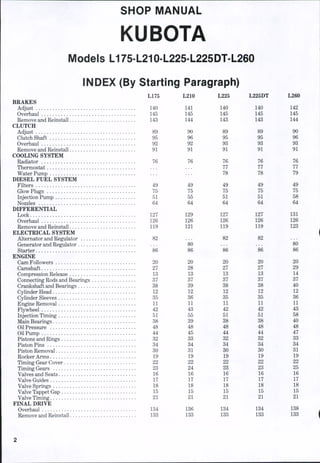
1. Figure 1 shows an exploded view of
fixed tread axle tyj)e used on Models
L175 and L225. Figure 2 is the adjusta-
ble axle used on Model L260, v^ith Model
L210 being basically similar. On all
models, front axle pivot pin (2) is re-
tained in support housing by set screw
(4). When assembling, make sure
tapered point of set screw enters locking
counterbore in pivot pin, and that
Fig. r - Exploded vl9w of fix-
ed tread front axle used on
Models U 75 and L22S.
27'
28
1. Front axle support
2. Pivot pin
3. Locknut
4. Set screw
5. f>ont axle
6. Thrust washers
7.
8.
!>.
11).
1 1.
12.
13.
14.
15.
Hi.
17.
' ^
?['•
23.
24.
21.
ZH.
2!).
30.
'}!;
'£.34.
35.
3fi.
37.
Bushi
Dra.t,^ link
link end
. Lncknut
. Crea:
Tie r
se fitting":
od
Tie rod end
Locknut
Steer
Cottt
Cast!
Boll
Nut'
Beari
Crea^
Key
i)ust
Creas
Beari
Hub
SpacT
Wash
Castlt
(^»tte
(iaske
Cap
"in^r arm
T ke'
e nut
;e seal
cnver
;e sen!
njr
T
er
' nut
r key
't
locknut (3) is securely tightened to pre-
vent set screw from loosening.
Renew pivot pin and/or axle pivot
bushings whenever diametral clearance
exceeds 0,5mm (0.020 inch) for Models
L175 and L225, or 0.45mm (0.018 inch)
for Models L210 and L260. Provisions
are not made for axle pivot end play ad-
justment; renew thrust washers (6) or
install a thin shim wiasher in FRONT of
axle, if end clearance is excessive.
TIE RODS AND TOE-IN
All Models
2. Tie rod and drag link ends are auto-
motive type. Adjust toe-in to 2-8 mm
(1/8-5/16 inch) by shortening or length-
ening tie rod. Steering drag link can be
adjusted if necessary, to permit a full
turn in either direction.
STEERING SPINDLE
All Models
3. Refer to Fig. 1 for exploded view of
front axle and associated parts of the
type used on Models L175 and L225, and
to Fig. 2 for view of front axle used on
Model L260. Refer to Fig. 3 for an ex-
ploded view of spindle and hub com-
6. SHOP MANUAL Paragraphs 1-3
CONDENSED SERVICE DATA, CONT.
L175 L210 L225 L225DT L260
SIZES - CAPACITIES - CLEARANCES, CONT.
Hydraulic System (Liters) Trans, 7,03 Trans. Trans. 6
^ ^ ^ Reservoir Reservoir Reservoir
(U.S. Quarts) Trans. 7.4 Trans. Trans. 6.3
Reservoir Reservoir Reservoir
Fluid Type SAE 80 #140 SAE 80 SAE 80 #140
Gear Lube Turbine Oil Gear Lube Gear Lube Turbine Oil
hvoni Axle Differential Case-
(Liters) ^05
(U.S. Quarts) _ ^
P^luid Type ;" gAE 90 'Z
^ , , ^ Gear Lube
r ront Axle Gearcase (Liters) Q Q^
(U.S. Quarts) :;;" *"" 0 9
Type ;; SAE 90 'Z
Gear Lube
FRONT AXLE AND STEERING SYSTEM
(Models L175-L210-L225-L260)
FRONT AXLE
All Models
1. Figure 1 shows an exploded view of
fixed tread axle tyj)e used on Models
L175 and L225. Figure 2 is the adjusta-
ble axle used on Model L260, v^ith Model
L210 being basically similar. On all
models, front axle pivot pin (2) is re-
tained in support housing by set screw
(4). When assembling, make sure
tapered point of set screw enters locking
counterbore in pivot pin, and that
Fig. r - Exploded vl9w of fix-
ed tread front axle used on
Models U 75 and L22S.
27'
28
1. Front axle support
2. Pivot pin
3. Locknut
4. Set screw
5. f>ont axle
6. Thrust washers
7.
8.
!>.
11).
1 1.
12.
13.
14.
15.
Hi.
17.
' ^
?['•
23.
24.
21.
ZH.
2!).
30.
'}!;
'£.34.
35.
3fi.
37.
Bushi
Dra.t,^ link
link end
. Lncknut
. Crea:
Tie r
se fitting":
od
Tie rod end
Locknut
Steer
Cottt
Cast!
Boll
Nut'
Beari
Crea^
Key
i)ust
Creas
Beari
Hub
SpacT
Wash
Castlt
(^»tte
(iaske
Cap
"in^r arm
T ke'
e nut
;e seal
cnver
;e sen!
njr
T
er
' nut
r key
't
locknut (3) is securely tightened to pre-
vent set screw from loosening.
Renew pivot pin and/or axle pivot
bushings whenever diametral clearance
exceeds 0,5mm (0.020 inch) for Models
L175 and L225, or 0.45mm (0.018 inch)
for Models L210 and L260. Provisions
are not made for axle pivot end play ad-
justment; renew thrust washers (6) or
install a thin shim wiasher in FRONT of
axle, if end clearance is excessive.
TIE RODS AND TOE-IN
All Models
2. Tie rod and drag link ends are auto-
motive type. Adjust toe-in to 2-8 mm
(1/8-5/16 inch) by shortening or length-
ening tie rod. Steering drag link can be
adjusted if necessary, to permit a full
turn in either direction.
STEERING SPINDLE
All Models
3. Refer to Fig. 1 for exploded view of
front axle and associated parts of the
type used on Models L175 and L225, and
to Fig. 2 for view of front axle used on
Model L260. Refer to Fig. 3 for an ex-
ploded view of spindle and hub com-
7. Paragraph 4
Fig. 2-Exploded view of ad-
justable tread front axle us-
ed on Model L260. Axle used
on L210 is basically similar.
Refer to Fig. 3 for identifi-
cation of spindie and hub
components used on Modei
L210. For parts Identifica-
tion refer to legend in Fig. 1
except for the foilowing:
38. Axle extension
39. Castle nut
40. Cotter key
KUBOTA
ponents used on Model L210. On all
models, steering arm upper clamp bolt
fits a notch in spindle shaft and clamp
bolt must be removed before steering
arm and spindle can be removed.
Spindle bushings are pre-sized and can
be renewed after spindle is withdrawn.
Upper and lower bushings are inter-
changeable. Maximum recommended
diametral clearance is 0.4mm (0.016
inch) for Models L175 and L225, and
0.475mm (0.019 inch) for Models L210
and L260.
STEERING GEAR
All Models
4. All models use a recirculating ball
nut steering gear of the type shown in
Fig. 4. To remove or disassemble steer-
ing gear, first remove hood, instrument
panel, cowl and fuel tank.
40
42
41
27
Fig. 4-Expioded view of recirculating ball nut steering used on
Models LI 75, L225 and L22$DT. Although details may differ, steering
used on Models L2W and L260 is basically similar. During
reassembiy, aiign marks on sector shaft teeth (20} and worm gear
(i2) as shown in Inset.
Fig, 3 —Exploded view of spindie and hub components used on
Model L2W. For parts identification, refer to legend in Fig. 1 except
for the following:
41. Spacer
42. "O"ring
43. Seal
44. Collar
45. Tooth washer
46. Locknut
1. Cap
2. Nut
3. Lockwasher
4. Steering wheel
5. Bushing
6. Key
7. Column
8. Cover
9. Shim
10. Seal
11. Bearing
12. Worm gear & shaft
13. Plug
14. Housing
15. Seal
16. Pitman arm
17. Lockwasher
18. Nut
19. Gasket
20. Sector shaft
21. Adjusting screw
22. Shim
23. Cover
24. Gasket
25. Nut
26. Plug
8. SHOP MANUAL
Steering wheel and pitman arm can be
removed with suitable pullers. Remove
pitman arm, then remove any existing
paint, rust or burrs from arm end of pit-
man shaft. Remove cap screws retaining
right side cover and remove cover along
with pitman shaft and gear. Steering
wheel shaft end play is controlled by
thickness of shim pack (9). Add or re-
move shims as required to limit end play
to 0.2mm (0.008 inch). Shaft and ball nut
is available only as an assembled unit
and disassembly is not recommended.
End clearance of adjusting screw (21)
in slot of pitman shaft (20) is controlled
by selective thickness shim (22) which is
available in five thicknesses. Use
thickest shim which can be installed,
when unit is assembled. Make sure
center tooth on shaft gear enters center
tooth space on ball nut as shown in inset.
Paragraphs 4A-6
Align marked splines on pitman arm (16)
and shaft (20). With unit completely
assembled and pitman arm (16) pointing
straight down, turn adjusting screw (21)
clockwise until all backlash is removed
from pitman arm shaft and a very slight
resistance is felt as pitman arm passes
center position. Fill steering gear hous-
ing, using 300mL (% pint) SAE 90 gear
oil. Complete tractor assembly by re-
versing disassembly procedure.
FRONT-WHEEL DRIVE
(Modei L225DT)
Front-wheel drive assembly includes
transfer case, drive shaft, front axle, dif-
ferential, axle shafts and axle hub
assemblies. The transfer case bolts to
the left side of transmission housing.
Transmission oil lubricates transfer case
assembly.
TIE RODS AND TOE-IN
4A. Tie rod drag link ends are auto-
motive type. Adjust toe-in to 2-8 mm
(1/8-5/16 inch) by shortening or length-
ening tie rod. Steering drag link can be
adjusted if necessary, to permit a full
turn in either direction.
FRONT AXLE
5. REMOVE AND REINSTALL.
Support tractor behind front axle and
detach front of drag link from steering
arm. Support axle level with floor to
prevent tipping and move transfer case
lever to "disengaged" position. Remove
front support center pin, then carefully
lower axle assembly until it can be with-
drawn from drive shaft splines.
Reinstall in reverse order of removal.
Tighten drag link end nut to 29.5-49,2
N-m (21.7-36.2 ft.-lbs.) torque.
NOTE: Add 0.19 liter (0.2 quart) of SAE
90 gear lube to differential case to repiace
gear lube lost when drive shaft yoke was
withdrawn from pinion shaft.
OUTER DRIVE ASSEMBLY
6, R&R AND OVERHAUL. To
disassemble outer drive assembly, first
remove wheel from side to be serviced.
Remove cap screws securing outer cover
(69-Fig. 5) to housing (58), then with-
draw cover with components (59, 60, 61,
62, 70 and 71) and allow oil to drain into
a suitable container. Remove nut (59)
from wheel axle (71) to separate com-
ponents.
16
23
51
52
54
55
Fig. S-Exploded view of front-wheel drive axle used on Model L22SDT.
1.
2.
8.
4.
5.
6.
7.
8.
9.
10.
11.
12.
13.
14.
15.
16.
17.
18.
Bevel pinion
"0" ring
Bearing
Spacer
Snap ring
Bearing
Shim
Bearing case
Collar
Oil seal
"0" ring-
Nut
Cover
Bushing
Bearing
Spindle housing
Pin
Front axle housing
19.
20.
21.
22.
23.
24.
25.
26.
27.
28.
29.
30.
31.
32.
33.
34.
35.
36.
Bearing
Dust seal
Gasket
Plug
Thrust washer
Side gear
Spider gear
Bushing
Thrust vt'asher
Guide plate
Oil seal
Shim
Bearing
Key
Cross shaft
Bevel ring gear
Differential case
Lock plate
37.
38.
39.
40.
41.
42.
43.
44.
45.
46.
47.
48.
49.
50.
51.
52.
53.
54.
Shim
"0" ring
Spindle housing
Plate
Felt seal
Plate
Dust seal
Dust seal holder
Gasket
Bushing
Y.-ke shaft
Universal joint
Yoke shaft
Pin & steering arm
Tie rod
Locknut
Tie rod end
"0" ring
55. Pin & steering arm
56. Gasket
57. Plug
58. Outer drive housing
59. Nut
60. Bearing
61. C^ear
62. Bearing
63. Oil seal
64. Bearing
65. Gear
66. Bearing
67. Snap ring
68. Gasket
69. Outer cover
70. Oil seal
71. Wheel axle
9. Thank you very much for
your reading. Please Click
Here. Then Get COMPLETE
MANUAL. NO WAITING
NOTE:
If there is no response to
click on the link above,
please download the PDF
document first and then
click on it.
10. SHOP MANUAL
Steering wheel and pitman arm can be
removed with suitable pullers. Remove
pitman arm, then remove any existing
paint, rust or burrs from arm end of pit-
man shaft. Remove cap screws retaining
right side cover and remove cover along
with pitman shaft and gear. Steering
wheel shaft end play is controlled by
thickness of shim pack (9). Add or re-
move shims as required to limit end play
to 0.2mm (0.008 inch). Shaft and ball nut
is available only as an assembled unit
and disassembly is not recommended.
End clearance of adjusting screw (21)
in slot of pitman shaft (20) is controlled
by selective thickness shim (22) which is
available in five thicknesses. Use
thickest shim which can be installed,
when unit is assembled. Make sure
center tooth on shaft gear enters center
tooth space on ball nut as shown in inset.
Paragraphs 4A-6
Align marked splines on pitman arm (16)
and shaft (20). With unit completely
assembled and pitman arm (16) pointing
straight down, turn adjusting screw (21)
clockwise until all backlash is removed
from pitman arm shaft and a very slight
resistance is felt as pitman arm passes
center position. Fill steering gear hous-
ing, using 300mL (% pint) SAE 90 gear
oil. Complete tractor assembly by re-
versing disassembly procedure.
FRONT-WHEEL DRIVE
(Modei L225DT)
Front-wheel drive assembly includes
transfer case, drive shaft, front axle, dif-
ferential, axle shafts and axle hub
assemblies. The transfer case bolts to
the left side of transmission housing.
Transmission oil lubricates transfer case
assembly.
TIE RODS AND TOE-IN
4A. Tie rod drag link ends are auto-
motive type. Adjust toe-in to 2-8 mm
(1/8-5/16 inch) by shortening or length-
ening tie rod. Steering drag link can be
adjusted if necessary, to permit a full
turn in either direction.
FRONT AXLE
5. REMOVE AND REINSTALL.
Support tractor behind front axle and
detach front of drag link from steering
arm. Support axle level with floor to
prevent tipping and move transfer case
lever to "disengaged" position. Remove
front support center pin, then carefully
lower axle assembly until it can be with-
drawn from drive shaft splines.
Reinstall in reverse order of removal.
Tighten drag link end nut to 29.5-49,2
N-m (21.7-36.2 ft.-lbs.) torque.
NOTE: Add 0.19 liter (0.2 quart) of SAE
90 gear lube to differential case to repiace
gear lube lost when drive shaft yoke was
withdrawn from pinion shaft.
OUTER DRIVE ASSEMBLY
6, R&R AND OVERHAUL. To
disassemble outer drive assembly, first
remove wheel from side to be serviced.
Remove cap screws securing outer cover
(69-Fig. 5) to housing (58), then with-
draw cover with components (59, 60, 61,
62, 70 and 71) and allow oil to drain into
a suitable container. Remove nut (59)
from wheel axle (71) to separate com-
ponents.
16
23
51
52
54
55
Fig. S-Exploded view of front-wheel drive axle used on Model L22SDT.
1.
2.
8.
4.
5.
6.
7.
8.
9.
10.
11.
12.
13.
14.
15.
16.
17.
18.
Bevel pinion
"0" ring
Bearing
Spacer
Snap ring
Bearing
Shim
Bearing case
Collar
Oil seal
"0" ring-
Nut
Cover
Bushing
Bearing
Spindle housing
Pin
Front axle housing
19.
20.
21.
22.
23.
24.
25.
26.
27.
28.
29.
30.
31.
32.
33.
34.
35.
36.
Bearing
Dust seal
Gasket
Plug
Thrust washer
Side gear
Spider gear
Bushing
Thrust vt'asher
Guide plate
Oil seal
Shim
Bearing
Key
Cross shaft
Bevel ring gear
Differential case
Lock plate
37.
38.
39.
40.
41.
42.
43.
44.
45.
46.
47.
48.
49.
50.
51.
52.
53.
54.
Shim
"0" ring
Spindle housing
Plate
Felt seal
Plate
Dust seal
Dust seal holder
Gasket
Bushing
Y.-ke shaft
Universal joint
Yoke shaft
Pin & steering arm
Tie rod
Locknut
Tie rod end
"0" ring
55. Pin & steering arm
56. Gasket
57. Plug
58. Outer drive housing
59. Nut
60. Bearing
61. C^ear
62. Bearing
63. Oil seal
64. Bearing
65. Gear
66. Bearing
67. Snap ring
68. Gasket
69. Outer cover
70. Oil seal
71. Wheel axle
11. Paragraphs 7-8 KUBOTA
Examine gears (61 and 65) for chip-
ped, cracked or missing teeth. Inspect
all bearings for roughness, cracks, cor-
rosion, excessive wear or any other
damage. Inspect cover (69) for cracks or
any other damage. Renew all parts as
needed.
Reassembly is reverse order of dis-
assembly. Tighten nut (59) to 147-196
N-m (108.5-144.7 ft.-lbs.) torque. Install
new gasket (68), then install outer cover
(69) with assembled components and
tighten securing cap screws to 48-56
N-m (35.4-41.2 ft.-lbs.) torque. Remove
plug (57) and fill axle gearcase with
0.85 liter (0,9 quart) of SAE 90 gear
lube. Reinstall wheel and tighten lug
nuts to 77.4-90.2 N-m (57.1-66,5 ft.-lbs.)
torque.
OUTER DRIVE HOUSING, KING
PINS, AXLE SHAFTS AND
SPINDLE HOUSING
7. R&R AND OVERHAUL. Remove
outer drive assembly as outlined in para-
graph 6, Detach tie rod end (53-Fig, 5)
from steering arm (55). Remove cap
screws securing plates, gasket and seal
parts (40 through 45) to housing (58),
then slide components toward center.
Remove snap ring (67), then slide bear-
ing (66) and gear (65) from yoke shaft
(49). Unbolt and remove king pins (50
and 55). Lift outer drive housing (58)
from spindle housing (39). Slide plates,
gasket and seal parts (40 through 45) off
spindle housing (39). Withdraw axle
shaft assembly (47, 48 and 49). Remove
cap screws securing spindle housing (39)
to axle housing (18) and separate com-
ponents, while preventing possible
movement of differential away from
axle housing.
Inspect all bearings for roughness,
corrosion, cracks, excessive wear or any
other damage. Examine king pin
bushings (46) for excessive wear, stan-
dard king pin bushing inner diameter is
25.1-25.133 mm (0.989-0.99 inch). In-
spect axle shaft and splines for excessive
wear or any other damage. Inspect uni-
versal joint (48) for binding, roughness,
excessive wear or any other damage.
Examine outer drive housing (58) and
spindle housing (39) for cracks, ex-
cessive wear or any other damage.
Renew all parts as needed.
Reassembly is reverse order of
disassembly. Renew all gaskets and
seals during reassembly. Lubricate king
pins with a good quality, multi-purpose,
lithium base grease, then slide into posi-
tion.
NOTE: King pins should slide freely Into
bushing bores with just hand pressure;
DO NOT drive king pins in with a hammer.
36
37
33
Fig. 6-Exploded Wew of transfer case assembly and associated components used on Model
L225DT.
1. Snap ring
2. Shaft
3. Collar
4. Needle bearing
5. Gear
6. Snap ring
7. Collar
8. Needle bearing
9. Gear
10. Needle bearing
11. Gear
12. Pin
13. Shift fork
14. Sliding gear
15. Bearing
16. Front plate
17. Gasket
18. Oil seal
19. Oil seal
20. Bearing
21. Splined shaft
22. Housing
23. Stop plate
24. "0" ring
25. Shaft
26. Shaft
27. "0" ring
28. Plug
29. Pin
30. Ball
31. Spring
32. Gasket
33. Plug
34. Rail
35. Shift lever holder
36. Pin
37. Oil seal
38. Shift lever
39. Grip
Tighten cap screws securing spindle
housing (39) and king pins (50 and 55) to
48-56 N-m (35,4-41.2 ft.-lbs.). Tighten
tie rod end nut to 29.5-49.2 N-m
(21,7-36.2 ftylbs.). Complete reassembly
as outlined in paragraph 6.
DIFFERENTIAL AND BEVEL
GEAR ASSEMBLY
8, R&R AND OVERHAUL. Remove
outer drive housing, king pins, axle
shafts and left spindle housing as out-
lined in paragraph 7. Lift differential
and bevel ring gear assembly (23
through 36-Fig. 5) from axle housing
(18). Remove cap screws securing bear-
ing case (8), then withdraw bevel pinion
assembly (1 through 13) from axle hous-
ing.
To separate bevel pinion assembly.
first remove screws securing cover (13)
to bearing case (8) and separate. Place
bevel pinion (1) in a suitable holding fix-
ture, then remove nut (12) from pinion
shaft. Complete disassembly with
reference to Fig. 5.
Inspect bearings (3 and 6) for rough-
ness, corrosion, cracks, excessive wear
or any other damage. Inspect bevel pi-
nion (1) for missing or chipped teeth, ex-
cessive wear or any other damage. Ex-
amine bearing case (8) for cracks, ex-
cessive wear or any other damage.
Renew all parts as needed.
NOTE: Bevei pinion (1) and bevei ring
gear (34) must be renewed as a matched
set.
Reassembly is reverse order of dis-
assembly. Renew "0" rings (2 and 11)
and oil seal (10). Tighten nut (12) to
196-245 N-m (145-180 ft.-lbs,) torque.
8