
Recommended
Recommended
More Related Content
More from fjjsjekfkskekme
More from fjjsjekfkskekme (20)
Perkins new 1000 series models ak diesel engine service repair manual
- 1. i Perkins New 1000 Series Models AJ to AS and YG to YK WORKSHOP MANUAL 4 and 6 cylinder diesel engines for industrial and agricultural applications Publication TPD 1350E, Issue 4. © Proprietary information of Perkins Engines Company Limited, all rights reserved. The information is correct at the time of print. Published in December 2001 by Technical Publications. This document has been printed from SPI². Not for Resale
- 2. ii Perkins Approved Clear English This publication is written in Chapters 1 General information 2 Specifications 3 Cylinder head assembly 4 Piston and connecting rod assemblies 5 Crankshaft assembly 6 Timing case and drive assembly 7 Cylinder block assembly 8 Engine timing 9 Aspiration system 10 Lubrication system 11 Fuel system 12 Cooling system 13 Flywheel and housing 14 Electrical equipment 15 Auxiliary equipment 16 Special tools The following pages contain a detailed table of contents This document has been printed from SPI². Not for Resale
- 3. Workshop Manual, TPD 1350E, Issue 4 iii New 1000 Series Contents 1 General information Introduction ... ... ... ... ... ... ... ... ... ... ... ... ... ... ... ... ... ... ... ... ... ... ... ... ... ... ... ... ... ... 1 Engine views . ... ... ... ... ... ... ... ... ... ... ... ... ... ... ... ... ... ... ... ... ... ... ... ... ... ... ... ... ... 2 Engine identification . ... ... ... ... ... ... ... ... ... ... ... ... ... ... ... ... ... ... ... ... ... ... ... ... ... ... 3 Safety precautions ... ... ... ... ... ... ... ... ... ... ... ... ... ... ... ... ... ... ... ... ... ... ... ... ... ... ... 5 Viton seals . ... ... ... ... ... ... ... ... ... ... ... ... ... ... ... ... ... ... ... ... ... ... ... ... ... ... ... ... ... ... 6 Engine lift equipment ... ... ... ... ... ... ... ... ... ... ... ... ... ... ... ... ... ... ... ... ... ... ... ... ... ... 7 POWERPART recommended consumable products . ... ... ... ... ... ... ... ... ... ... ... ... ... 8 2 Specifications Basic engine data . ... ... ... ... ... ... ... ... ... ... ... ... ... ... ... ... ... ... ... ... ... ... ... ... ... ... . 11 Data and dimensions ... ... ... ... ... ... ... ... ... ... ... ... ... ... ... ... ... ... ... ... ... ... ... ... ... . 12 Thread sealant ... ... ... ... ... ... ... ... ... ... ... ... ... ... ... ... ... ... ... ... ... ... ... ... ... ... ... ... . 35 Standard torque tensions ... ... ... ... ... ... ... ... ... ... ... ... ... ... ... ... ... ... ... ... ... ... ... . 36 Specific torque tensions .. ... ... ... ... ... ... ... ... ... ... ... ... ... ... ... ... ... ... ... ... ... ... ... . 37 Compression test data . ... ... ... ... ... ... ... ... ... ... ... ... ... ... ... ... ... ... ... ... ... ... ... ... . 40 This document has been printed from SPI². Not for Resale
- 4. iv Workshop Manual, TPD 1350E, Issue 4 New 1000 Series 3 Cylinder head assembly General description ... ... ... ... ... ... ... ... ... ... ... ... ... ... ... ... ... ... ... ... ... ... ... ... ... ... 41 Rocker cover Operation 3-1 To remove ... ... ... ... ... ... ... ... ... ... ... ... ... ... ... ... ... ... ... ... ... ... ... ... 42 Operation 3-2 To fit ... ... ... ... ... ... ... ... ... ... ... ... ... ... ... ... ... ... ... ... ... ... ... ... ... ... 43 Rocker assembly Operation 3-3 To remove and to fit ... ... ... ... ... ... ... ... ... ... ... ... ... ... ... ... ... ... ... ... 44 Operation 3-4 To dismantle and to assemble ... ... ... ... ... ... ... ... ... ... ... ... ... ... ... ... 45 Operation 3-5 To inspect and to correct ... ... ... ... ... ... ... ... ... ... ... ... ... ... ... ... ... ... 45 Valve tip clearances Operation 3-6 To check and to adjust (four cylinder engines) ... ... ... ... ... ... ... ... ... ... 46 Operation 3-7 To check and to adjust (six cylinder engines) . ... ... ... ... ... ... ... ... ... ... 47 Valve springs Operation 3-8 To change the valve springs (with cylinder head fitted) .. ... ... ... ... ... ... 48 Manifolds ... ... ... ... ... ... ... ... ... ... ... ... ... ... ... ... ... ... ... ... ... ... ... ... ... ... ... ... ... ... 50 Operation 3-9 To remove and to fit an intake manifold .. ... ... ... ... ... ... ... ... ... ... ... ... 50 Operation 3-10 To remove and to fit an exhaust manifold (one-piece) .. ... ... ... ... ... ... 52 Operation 3-11 To remove and to fit an exhaust manifold (three-piece) ... ... ... ... ... ... 54 Cylinder head assembly Operation 3-12 To remove . ... ... ... ... ... ... ... ... ... ... ... ... ... ... ... ... ... ... ... ... ... ... ... 56 Operation 3-13 To fit (engine types AJ to AQ and YG to YK) ... ... ... ... ... ... ... ... ... ... 58 Operation 3-14 To fit (engine types AR and AS) ... ... ... ... ... ... ... ... ... ... ... ... ... ... ... 61 Valves and valve springs Operation 3-15 To remove . ... ... ... ... ... ... ... ... ... ... ... ... ... ... ... ... ... ... ... ... ... ... ... 64 Operation 3-16 To fit .. ... ... ... ... ... ... ... ... ... ... ... ... ... ... ... ... ... ... ... ... ... ... ... ... ... 65 Operation 3-17 To inspect and to correct .. ... ... ... ... ... ... ... ... ... ... ... ... ... ... ... ... ... 66 Valve guides ... ... ... ... ... ... ... ... ... ... ... ... ... ... ... ... ... ... ... ... ... ... ... ... ... ... ... ... ... 67 Operation 3-18 To inspect . ... ... ... ... ... ... ... ... ... ... ... ... ... ... ... ... ... ... ... ... ... ... ... 67 Operation 3-19 To remove . ... ... ... ... ... ... ... ... ... ... ... ... ... ... ... ... ... ... ... ... ... ... ... 68 Operation 3-20 To fit .. ... ... ... ... ... ... ... ... ... ... ... ... ... ... ... ... ... ... ... ... ... ... ... ... ... 69 Cylinder head Operation 3-21 To inspect and to correct .. ... ... ... ... ... ... ... ... ... ... ... ... ... ... ... ... ... 70 Operation 3-22 To correct a valve seat with a valve seat cutter ... ... ... ... ... ... ... ... ... 71 Operation 3-23 To fit valve seat inserts . ... ... ... ... ... ... ... ... ... ... ... ... ... ... ... ... ... ... 73 This document has been printed from SPI². Not for Resale
- 5. Workshop Manual, TPD 1350E, Issue 4 v New 1000 Series 4 Piston and connecting rod assemblies General description .. ... ... ... ... ... ... ... ... ... ... ... ... ... ... ... ... ... ... ... ... ... ... ... ... ... . 75 Big end bearing Operation 4-1 To remove .. ... ... ... ... ... ... ... ... ... ... ... ... ... ... ... ... ... ... ... ... ... ... ... . 77 Operation 4-2 To fit ... ... ... ... ... ... ... ... ... ... ... ... ... ... ... ... ... ... ... ... ... ... ... ... ... ... . 78 Operation 4-3 To inspect ... ... ... ... ... ... ... ... ... ... ... ... ... ... ... ... ... ... ... ... ... ... ... ... . 78 Piston and connecting rod Operation 4-4 To remove .. ... ... ... ... ... ... ... ... ... ... ... ... ... ... ... ... ... ... ... ... ... ... ... . 79 Operation 4-5 To fit ... ... ... ... ... ... ... ... ... ... ... ... ... ... ... ... ... ... ... ... ... ... ... ... ... ... . 80 Operation 4-6 To check the piston height above the cylinder block .. ... ... ... ... ... ... ... . 82 Piston rings Operation 4-7 To remove .. ... ... ... ... ... ... ... ... ... ... ... ... ... ... ... ... ... ... ... ... ... ... ... . 83 Operation 4-8 To fit ... ... ... ... ... ... ... ... ... ... ... ... ... ... ... ... ... ... ... ... ... ... ... ... ... ... . 84 Piston and connecting rod assembly Operation 4-9 To dismantle ... ... ... ... ... ... ... ... ... ... ... ... ... ... ... ... ... ... ... ... ... ... ... . 85 Operation 4-10 To assemble . ... ... ... ... ... ... ... ... ... ... ... ... ... ... ... ... ... ... ... ... ... ... . 86 Operation 4-11 To check the length of a connecting rod .. ... ... ... ... ... ... ... ... ... ... ... . 87 Piston and piston rings Operation 4-12 To inspect . ... ... ... ... ... ... ... ... ... ... ... ... ... ... ... ... ... ... ... ... ... ... ... . 88 Connecting rod Operation 4-13 To inspect . ... ... ... ... ... ... ... ... ... ... ... ... ... ... ... ... ... ... ... ... ... ... ... . 89 Partially finished small end bush Operation 4-14 To remove and to fit . ... ... ... ... ... ... ... ... ... ... ... ... ... ... ... ... ... ... ... . 90 Piston cooling jets Operation 4-15 To remove and to fit . ... ... ... ... ... ... ... ... ... ... ... ... ... ... ... ... ... ... ... . 91 Operation 4-16 To check the jet alignment ... ... ... ... ... ... ... ... ... ... ... ... ... ... ... ... ... . 92 5 Crankshaft assembly General description .. ... ... ... ... ... ... ... ... ... ... ... ... ... ... ... ... ... ... ... ... ... ... ... ... ... . 93 Crankshaft pulley Operation 5-1 To remove and to fit (four cylinder engines) ... ... ... ... ... ... ... ... ... ... ... . 95 This document has been printed from SPI². Not for Resale
- 6. vi Workshop Manual, TPD 1350E, Issue 4 New 1000 Series Crankshaft pulley and damper Operation 5-2 To remove (six cylinder engines) ... ... ... ... ... ... ... ... ... ... ... ... ... ... ... 96 Operation 5-3 To fit (six cylinder engines) . ... ... ... ... ... ... ... ... ... ... ... ... ... ... ... ... ... 97 Operation 5-4 To inspect ... ... ... ... ... ... ... ... ... ... ... ... ... ... ... ... ... ... ... ... ... ... ... ... 98 Rear oil seal assembly .. ... ... ... ... ... ... ... ... ... ... ... ... ... ... ... ... ... ... ... ... ... ... ... ... 99 Operation 5-5 To remove and to fit (one-piece assembly) . ... ... ... ... ... ... ... ... ... ... ... 99 Operation 5-6 To remove and to fit (two-piece assembly) . ... ... ... ... ... ... ... ... ... ... .. 102 Operation 5-7 To renew the rear end oil seal (two-piece assembly) ... ... ... ... ... ... .. 103 Operation 5-8 To remove and to fit a wear sleeve . ... ... ... ... ... ... ... ... ... ... ... ... ... .. 104 Thrust washers Operation 5-9 To check crankshaft end-float . ... ... ... ... ... ... ... ... ... ... ... ... ... ... ... .. 105 Operation 5-10 To remove . ... ... ... ... ... ... ... ... ... ... ... ... ... ... ... ... ... ... ... ... ... ... .. 106 Operation 5-11 To fit .. ... ... ... ... ... ... ... ... ... ... ... ... ... ... ... ... ... ... ... ... ... ... ... ... .. 107 Main bearings Operation 5-12 To remove (with the crankshaft in position) .. ... ... ... ... ... ... ... ... ... .. 108 Operation 5-13 To fit .. ... ... ... ... ... ... ... ... ... ... ... ... ... ... ... ... ... ... ... ... ... ... ... ... .. 109 Operation 5-14 To inspect . ... ... ... ... ... ... ... ... ... ... ... ... ... ... ... ... ... ... ... ... ... ... .. 109 Crankshaft Operation 5-15 To remove . ... ... ... ... ... ... ... ... ... ... ... ... ... ... ... ... ... ... ... ... ... ... .. 110 Operation 5-16 To fit .. ... ... ... ... ... ... ... ... ... ... ... ... ... ... ... ... ... ... ... ... ... ... ... ... .. 111 Operation 5-17 To inspect . ... ... ... ... ... ... ... ... ... ... ... ... ... ... ... ... ... ... ... ... ... ... .. 113 Balancer unit Operation 5-18 To remove and to fit .. ... ... ... ... ... ... ... ... ... ... ... ... ... ... ... ... ... ... .. 114 Operation 5-19 To dismantle . ... ... ... ... ... ... ... ... ... ... ... ... ... ... ... ... ... ... ... ... ... .. 115 Operation 5-20 To assemble . ... ... ... ... ... ... ... ... ... ... ... ... ... ... ... ... ... ... ... ... ... .. 117 Operation 5-21 To inspect . ... ... ... ... ... ... ... ... ... ... ... ... ... ... ... ... ... ... ... ... ... ... .. 120 Operation 5-22 To remove and to fit the needle roller bearings for the drive shaft ... .. 121 Operation 5-23 To remove and to fit the bushes for the balance weights . ... ... ... ... .. 122 6 Timing case and drive assembly General description ... ... ... ... ... ... ... ... ... ... ... ... ... ... ... ... ... ... ... ... ... ... ... ... ... .. 123 Timing case cover Operation 6-1 To remove ... ... ... ... ... ... ... ... ... ... ... ... ... ... ... ... ... ... ... ... ... ... ... .. 124 Operation 6-2 To fit ... ... ... ... ... ... ... ... ... ... ... ... ... ... ... ... ... ... ... ... ... ... ... ... ... .. 125 Front oil seal Operation 6-3 To remove ... ... ... ... ... ... ... ... ... ... ... ... ... ... ... ... ... ... ... ... ... ... ... .. 127 Operation 6-4 To fit ... ... ... ... ... ... ... ... ... ... ... ... ... ... ... ... ... ... ... ... ... ... ... ... ... .. 128 Operation 6-5 To remove and to fit a wear sleeve . ... ... ... ... ... ... ... ... ... ... ... ... ... .. 130 This document has been printed from SPI². Not for Resale
- 7. Workshop Manual, TPD 1350E, Issue 4 vii New 1000 Series Idler gear and hub Operation 6-6 To remove .. ... ... ... ... ... ... ... ... ... ... ... ... ... ... ... ... ... ... ... ... ... ... ... 131 Operation 6-7 To fit ... ... ... ... ... ... ... ... ... ... ... ... ... ... ... ... ... ... ... ... ... ... ... ... ... ... 133 Idler gear and hub for the compressor Operation 6-8 To remove .. ... ... ... ... ... ... ... ... ... ... ... ... ... ... ... ... ... ... ... ... ... ... ... 135 Operation 6-9 To fit ... ... ... ... ... ... ... ... ... ... ... ... ... ... ... ... ... ... ... ... ... ... ... ... ... ... 136 Fuel pump gear . ... ... ... ... ... ... ... ... ... ... ... ... ... ... ... ... ... ... ... ... ... ... ... ... ... ... ... 137 Operation 6-10 To remove ... ... ... ... ... ... ... ... ... ... ... ... ... ... ... ... ... ... ... ... ... ... ... 137 Operation 6-11 To fit . ... ... ... ... ... ... ... ... ... ... ... ... ... ... ... ... ... ... ... ... ... ... ... ... ... 139 Camshaft gear Operation 6-12 To remove and to fit . ... ... ... ... ... ... ... ... ... ... ... ... ... ... ... ... ... ... ... 141 Crankshaft gear Operation 6-13 To remove and to fit . ... ... ... ... ... ... ... ... ... ... ... ... ... ... ... ... ... ... ... 142 Timing case Operation 6-14 To remove ... ... ... ... ... ... ... ... ... ... ... ... ... ... ... ... ... ... ... ... ... ... ... 143 Operation 6-15 To fit . ... ... ... ... ... ... ... ... ... ... ... ... ... ... ... ... ... ... ... ... ... ... ... ... ... 144 Camshaft and tappets Operation 6-16 To remove ... ... ... ... ... ... ... ... ... ... ... ... ... ... ... ... ... ... ... ... ... ... ... 146 Operation 6-17 To fit . ... ... ... ... ... ... ... ... ... ... ... ... ... ... ... ... ... ... ... ... ... ... ... ... ... 147 7 Cylinder block assembly General description .. ... ... ... ... ... ... ... ... ... ... ... ... ... ... ... ... ... ... ... ... ... ... ... ... ... 149 Cylinder block Operation 7-1 To dismantle ... ... ... ... ... ... ... ... ... ... ... ... ... ... ... ... ... ... ... ... ... ... ... 150 Operation 7-2 To assemble ... ... ... ... ... ... ... ... ... ... ... ... ... ... ... ... ... ... ... ... ... ... ... 151 Operation 7-3 To inspect ... ... ... ... ... ... ... ... ... ... ... ... ... ... ... ... ... ... ... ... ... ... ... ... 152 Operation 7-4 To remove and to fit a new type ‘D’ plug to the tappet chamber ... ... ... 153 Cylinder liner Operation 7-5 To inspect ... ... ... ... ... ... ... ... ... ... ... ... ... ... ... ... ... ... ... ... ... ... ... ... 155 Operation 7-6 To remove .. ... ... ... ... ... ... ... ... ... ... ... ... ... ... ... ... ... ... ... ... ... ... ... 156 Operation 7-7 To fit a service liner ... ... ... ... ... ... ... ... ... ... ... ... ... ... ... ... ... ... ... ... 158 Operation 7-8 To fit a partially finished liner .. ... ... ... ... ... ... ... ... ... ... ... ... ... ... ... ... 161 Cylinder bore, engine types AR and AS Operation 7-9 To inspect ... ... ... ... ... ... ... ... ... ... ... ... ... ... ... ... ... ... ... ... ... ... ... ... 164 This document has been printed from SPI². Not for Resale
- 8. viii Workshop Manual, TPD 1350E, Issue 4 New 1000 Series 8 Engine timing General description ... ... ... ... ... ... ... ... ... ... ... ... ... ... ... ... ... ... ... ... ... ... ... ... ... .. 165 Engine timing Operation 8-1 To set number 1 piston to TDC on the compression stroke ... ... ... ... .. 167 Operation 8-2 Another method to set number 1 piston to TDC . ... ... ... ... ... ... ... ... .. 168 Operation 8-3 To check the valve timing ... ... ... ... ... ... ... ... ... ... ... ... ... ... ... ... ... .. 169 Operation 8-4 To check the timing of the fuel injection pump ... ... ... ... ... ... ... ... ... .. 170 9 Aspiration system General description ... ... ... ... ... ... ... ... ... ... ... ... ... ... ... ... ... ... ... ... ... ... ... ... ... .. 171 Turbocharger Operation 9-1 To remove ... ... ... ... ... ... ... ... ... ... ... ... ... ... ... ... ... ... ... ... ... ... ... .. 173 Operation 9-2 To fit ... ... ... ... ... ... ... ... ... ... ... ... ... ... ... ... ... ... ... ... ... ... ... ... ... .. 174 Operation 9-3 To clean the impeller and the compressor casing .. ... ... ... ... ... ... ... .. 176 Operation 9-4 To remove and to fit the actuator assembly of the waste-gate unit ... .. 177 Operation 9-5 To check and adjust the operation of the waste-gate . ... ... ... ... ... ... .. 178 Turbocharger faults ... ... ... ... ... ... ... ... ... ... ... ... ... ... ... ... ... ... ... ... ... ... ... ... ... .. 179 List of possible causes . ... ... ... ... ... ... ... ... ... ... ... ... ... ... ... ... ... ... ... ... ... ... ... .. 180 Open engine breather ... ... ... ... ... ... ... ... ... ... ... ... ... ... ... ... ... ... ... ... ... ... ... ... .. 181 Operation 9-6 To clean and to renew ... ... ... ... ... ... ... ... ... ... ... ... ... ... ... ... ... ... .. 181 Operation 9-7 To Inspect ... ... ... ... ... ... ... ... ... ... ... ... ... ... ... ... ... ... ... ... ... ... ... .. 183 Closed engine breather . ... ... ... ... ... ... ... ... ... ... ... ... ... ... ... ... ... ... ... ... ... ... ... .. 184 Operation 9-8 To renew the breather valve assembly ... ... ... ... ... ... ... ... ... ... ... ... .. 185 10 Lubrication system General description - four cylinder engine lubrication system ... ... ... ... ... ... ... .. 187 General description - Six cylinder engine lubrication system . ... ... ... ... ... ... ... .. 188 Filter canister Operation 10-1 To renew ... ... ... ... ... ... ... ... ... ... ... ... ... ... ... ... ... ... ... ... ... ... ... .. 191 Filter head Operation 10-2 To remove and to fit .. ... ... ... ... ... ... ... ... ... ... ... ... ... ... ... ... ... ... .. 192 Sump Operation 10-3 To remove and to fit .. ... ... ... ... ... ... ... ... ... ... ... ... ... ... ... ... ... ... .. 193 This document has been printed from SPI². Not for Resale
- 9. Workshop Manual, TPD 1350E, Issue 4 ix New 1000 Series Oil strainer and suction pipe Operation 10-4 To remove and to fit . ... ... ... ... ... ... ... ... ... ... ... ... ... ... ... ... ... ... ... 194 Operation 10-5 To inspect and to correct .. ... ... ... ... ... ... ... ... ... ... ... ... ... ... ... ... ... 195 Lubricating oil pump ... ... ... ... ... ... ... ... ... ... ... ... ... ... ... ... ... ... ... ... ... ... ... ... ... 196 Operation 10-6 To remove ... ... ... ... ... ... ... ... ... ... ... ... ... ... ... ... ... ... ... ... ... ... ... 196 Operation 10-7 To fit . ... ... ... ... ... ... ... ... ... ... ... ... ... ... ... ... ... ... ... ... ... ... ... ... ... 197 Operation 10-8 To inspect . ... ... ... ... ... ... ... ... ... ... ... ... ... ... ... ... ... ... ... ... ... ... ... 198 Lubricating oil pump idler gear shaft .. ... ... ... ... ... ... ... ... ... ... ... ... ... ... ... ... ... ... 199 Operation 10-9 To remove (six cylinder engines) . ... ... ... ... ... ... ... ... ... ... ... ... ... ... 199 Operation 10-10 To fit (six cylinder engines) . ... ... ... ... ... ... ... ... ... ... ... ... ... ... ... ... 201 Operation 10-11 To remove and to fit (four cylinder engines) ... ... ... ... ... ... ... ... ... ... 202 Relief valve Operation 10-12 To remove and to fit ... ... ... ... ... ... ... ... ... ... ... ... ... ... ... ... ... ... ... 203 Operation 10-13 To dismantle and to assemble ... ... ... ... ... ... ... ... ... ... ... ... ... ... ... 204 Operation 10-14 To inspect ... ... ... ... ... ... ... ... ... ... ... ... ... ... ... ... ... ... ... ... ... ... ... 204 Flexible oil pipes ... ... ... ... ... ... ... ... ... ... ... ... ... ... ... ... ... ... ... ... ... ... ... ... ... ... ... 205 Operation 10-15 To remove .. ... ... ... ... ... ... ... ... ... ... ... ... ... ... ... ... ... ... ... ... ... ... 205 Operation 10-16 To fit ... ... ... ... ... ... ... ... ... ... ... ... ... ... ... ... ... ... ... ... ... ... ... ... ... 206 Operation 10-17 To Inspect ... ... ... ... ... ... ... ... ... ... ... ... ... ... ... ... ... ... ... ... ... ... ... 207 11 Fuel system General description .. ... ... ... ... ... ... ... ... ... ... ... ... ... ... ... ... ... ... ... ... ... ... ... ... ... 209 Cold start advance unit ... ... ... ... ... ... ... ... ... ... ... ... ... ... ... ... ... ... ... ... ... ... ... ... 212 Typical fuel system ... ... ... ... ... ... ... ... ... ... ... ... ... ... ... ... ... ... ... ... ... ... ... ... ... ... 215 Fuel filters .. ... ... ... ... ... ... ... ... ... ... ... ... ... ... ... ... ... ... ... ... ... ... ... ... ... ... ... ... ... 216 Fuel filter element Operation 11-1 To renew - separate element type ... ... ... ... ... ... ... ... ... ... ... ... ... ... 217 Operation 11-2 To renew - canister type ... ... ... ... ... ... ... ... ... ... ... ... ... ... ... ... ... ... 218 Operation 11-3 To renew - quick release canister type . ... ... ... ... ... ... ... ... ... ... ... ... 219 Atomisers .. ... ... ... ... ... ... ... ... ... ... ... ... ... ... ... ... ... ... ... ... ... ... ... ... ... ... ... ... ... 220 Operation 11-4 To remove ... ... ... ... ... ... ... ... ... ... ... ... ... ... ... ... ... ... ... ... ... ... ... 221 Operation 11-5 To fit . ... ... ... ... ... ... ... ... ... ... ... ... ... ... ... ... ... ... ... ... ... ... ... ... ... 222 This document has been printed from SPI². Not for Resale
- 10. x Workshop Manual, TPD 1350E, Issue 4 New 1000 Series Fuel lift pump Operation 11-6 To remove and to fit .. ... ... ... ... ... ... ... ... ... ... ... ... ... ... ... ... ... ... .. 224 Operation 11-7 To dismantle . ... ... ... ... ... ... ... ... ... ... ... ... ... ... ... ... ... ... ... ... ... .. 225 Operation 11-8 To assemble . ... ... ... ... ... ... ... ... ... ... ... ... ... ... ... ... ... ... ... ... ... .. 226 Operation 11-9 To test ... ... ... ... ... ... ... ... ... ... ... ... ... ... ... ... ... ... ... ... ... ... ... ... .. 227 Bosch fuel injection pump ... ... ... ... ... ... ... ... ... ... ... ... ... ... ... ... ... ... ... ... ... ... .. 228 Operation 11-10 To remove ... ... ... ... ... ... ... ... ... ... ... ... ... ... ... ... ... ... ... ... ... ... .. 230 Operation 11-11 To fit ... ... ... ... ... ... ... ... ... ... ... ... ... ... ... ... ... ... ... ... ... ... ... ... .. 232 Operation 11-12 To adjust . ... ... ... ... ... ... ... ... ... ... ... ... ... ... ... ... ... ... ... ... ... ... .. 234 Lucas/Delphi DP 200 Series fuel injection pump ... ... ... ... ... ... ... ... ... ... ... ... ... .. 235 Operation 11-13 To remove ... ... ... ... ... ... ... ... ... ... ... ... ... ... ... ... ... ... ... ... ... ... .. 237 Operation 11-14 To fit ... ... ... ... ... ... ... ... ... ... ... ... ... ... ... ... ... ... ... ... ... ... ... ... .. 239 Operation 11-15 To adjust . ... ... ... ... ... ... ... ... ... ... ... ... ... ... ... ... ... ... ... ... ... ... .. 242 Operation 11-16 Electrical shut off solenoid (ESOS) . ... ... ... ... ... ... ... ... ... ... ... ... .. 243 Stanadyne fuel injection pump ... ... ... ... ... ... ... ... ... ... ... ... ... ... ... ... ... ... ... ... .. 245 Operation 11-17 To remove ... ... ... ... ... ... ... ... ... ... ... ... ... ... ... ... ... ... ... ... ... ... .. 248 Operation 11-18 To fit ... ... ... ... ... ... ... ... ... ... ... ... ... ... ... ... ... ... ... ... ... ... ... ... .. 249 Operation 11-19 To adjust . ... ... ... ... ... ... ... ... ... ... ... ... ... ... ... ... ... ... ... ... ... ... .. 251 Air in the fuel system ... ... ... ... ... ... ... ... ... ... ... ... ... ... ... ... ... ... ... ... ... ... ... ... .. 254 Operation 11-20 To eliminate air from the fuel system .. ... ... ... ... ... ... ... ... ... ... ... .. 254 12 Cooling system General description ... ... ... ... ... ... ... ... ... ... ... ... ... ... ... ... ... ... ... ... ... ... ... ... ... .. 257 Thermostats Operation 12-1 To remove ... ... ... ... ... ... ... ... ... ... ... ... ... ... ... ... ... ... ... ... ... ... .. 258 Operation 12-2 To fit .. ... ... ... ... ... ... ... ... ... ... ... ... ... ... ... ... ... ... ... ... ... ... ... ... .. 259 Operation 12-3 To test .. ... ... ... ... ... ... ... ... ... ... ... ... ... ... ... ... ... ... ... ... ... ... ... .. 260 Coolant pump - early gear driven pumps ... ... ... ... ... ... ... ... ... ... ... ... ... ... ... ... .. 261 Operation 12-4 To remove ... ... ... ... ... ... ... ... ... ... ... ... ... ... ... ... ... ... ... ... ... ... .. 261 Operation 12-5 To fit .. ... ... ... ... ... ... ... ... ... ... ... ... ... ... ... ... ... ... ... ... ... ... ... ... .. 262 Operation 12-6 To dismantle . ... ... ... ... ... ... ... ... ... ... ... ... ... ... ... ... ... ... ... ... ... .. 263 Operation 12-7 To assemble . ... ... ... ... ... ... ... ... ... ... ... ... ... ... ... ... ... ... ... ... ... .. 264 Operation 12-8 To remove and to fit a pressed steel cover (early coolant pumps) ... .. 267 Coolant pump - latest gear driven pumps ... ... ... ... ... ... ... ... ... ... ... ... ... ... ... ... .. 268 Operation 12-9 To remove . ... ... ... ... ... ... ... ... ... ... ... ... ... ... ... ... ... ... ... ... ... ... .. 268 Operation 12-10 To fit ... ... ... ... ... ... ... ... ... ... ... ... ... ... ... ... ... ... ... ... ... ... ... ... .. 269 Operation 12-11 To dismantle ... ... ... ... ... ... ... ... ... ... ... ... ... ... ... ... ... ... ... ... ... .. 270 Operation 12-12 To assemble ... ... ... ... ... ... ... ... ... ... ... ... ... ... ... ... ... ... ... ... ... .. 273 This document has been printed from SPI². Not for Resale
- 11. Workshop Manual, TPD 1350E, Issue 4 xi New 1000 Series Coolant pump - belt driven .. ... ... ... ... ... ... ... ... ... ... ... ... ... ... ... ... ... ... ... ... ... ... 277 Operation 12-13 To remove .. ... ... ... ... ... ... ... ... ... ... ... ... ... ... ... ... ... ... ... ... ... ... 277 Operation 12-14 To fit ... ... ... ... ... ... ... ... ... ... ... ... ... ... ... ... ... ... ... ... ... ... ... ... ... 279 Operation 12-15 To remove high position pump ... ... ... ... ... ... ... ... ... ... ... ... ... ... ... 281 Operation 12-16 To fit high position pump ... ... ... ... ... ... ... ... ... ... ... ... ... ... ... ... ... 283 Operation 12-17 To dismantle ... ... ... ... ... ... ... ... ... ... ... ... ... ... ... ... ... ... ... ... ... ... 285 Operation 12-18 To assemble ... ... ... ... ... ... ... ... ... ... ... ... ... ... ... ... ... ... ... ... ... ... 286 Fan Operation 12-19 To remove and to fit ... ... ... ... ... ... ... ... ... ... ... ... ... ... ... ... ... ... ... 289 Fan drive (engines with gear driven coolant pumps) Operation 12-20 To remove and to fit ... ... ... ... ... ... ... ... ... ... ... ... ... ... ... ... ... ... ... 290 Lubricating oil cooler Operation 12-21 To remove (four cylinder turbocharged engines) ... ... ... ... ... ... ... ... 291 Operation 12-22 To fit (four cylinder turbocharged engines) . ... ... ... ... ... ... ... ... ... ... 292 Operation 12-23 To dismantle and to assemble (four cylinder engines) ... ... ... ... ... ... 293 Operation 12-24 To remove (six cylinder turbocharged engines) . ... ... ... ... ... ... ... ... 294 Operation 12-25 To fit (six cylinder turbocharged engines) .. ... ... ... ... ... ... ... ... ... ... 296 Operation 12-26 To dismantle and to assemble (six cylinder engines) . ... ... ... ... ... ... 298 Operation 12-27 To remove and to fit (canister type) ... ... ... ... ... ... ... ... ... ... ... ... ... 300 Operation 12-28 To remove and to fit cooler bypass valve ... ... ... ... ... ... ... ... ... ... ... 300 Intercoolers ... ... ... ... ... ... ... ... ... ... ... ... ... ... ... ... ... ... ... ... ... ... ... ... ... ... ... ... ... 301 Horizontally mounted intercooler Operation 12-29 To remove .. ... ... ... ... ... ... ... ... ... ... ... ... ... ... ... ... ... ... ... ... ... ... 302 Operation 12-30 To fit ... ... ... ... ... ... ... ... ... ... ... ... ... ... ... ... ... ... ... ... ... ... ... ... ... 304 Vertically mounted intercooler Operation 12-31 To remove .. ... ... ... ... ... ... ... ... ... ... ... ... ... ... ... ... ... ... ... ... ... ... 306 Operation 12-32 To fit ... ... ... ... ... ... ... ... ... ... ... ... ... ... ... ... ... ... ... ... ... ... ... ... ... 307 Operation 12-33 To clean and to inspect .. ... ... ... ... ... ... ... ... ... ... ... ... ... ... ... ... ... 309 13 Flywheel and housing General description .. ... ... ... ... ... ... ... ... ... ... ... ... ... ... ... ... ... ... ... ... ... ... ... ... ... 311 Flywheel Operation 13-1 To remove and to fit . ... ... ... ... ... ... ... ... ... ... ... ... ... ... ... ... ... ... ... 311 Ring gear Operation 13-2 To remove and to fit . ... ... ... ... ... ... ... ... ... ... ... ... ... ... ... ... ... ... ... 312 Flywheel housing Operation 13-3 To remove and to fit . ... ... ... ... ... ... ... ... ... ... ... ... ... ... ... ... ... ... ... 313 This document has been printed from SPI². Not for Resale
- 12. xii Workshop Manual, TPD 1350E, Issue 4 New 1000 Series 14 Electrical equipment Alternators . ... ... ... ... ... ... ... ... ... ... ... ... ... ... ... ... ... ... ... ... ... ... ... ... ... ... ... ... .. 315 Operation 14-1 To check the drive belts ... ... ... ... ... ... ... ... ... ... ... ... ... ... ... ... ... .. 316 Operation 14-2 To adjust drive belt tension ... ... ... ... ... ... ... ... ... ... ... ... ... ... ... ... .. 317 Operation 14-3 To remove and to fit the drive belts ... ... ... ... ... ... ... ... ... ... ... ... ... .. 318 Operation 14-4 To remove and to fit the alternator ... ... ... ... ... ... ... ... ... ... ... ... ... .. 319 Operation 14-5 To maintain ... ... ... ... ... ... ... ... ... ... ... ... ... ... ... ... ... ... ... ... ... ... .. 319 Operation 14-6 Fault diagnosis .. ... ... ... ... ... ... ... ... ... ... ... ... ... ... ... ... ... ... ... ... .. 320 Starter motors ... ... ... ... ... ... ... ... ... ... ... ... ... ... ... ... ... ... ... ... ... ... ... ... ... ... ... .. 322 Operation 14-7 To remove and to fit .. ... ... ... ... ... ... ... ... ... ... ... ... ... ... ... ... ... ... .. 323 Operation 14-8 To maintain the brush gear and the commutator .. ... ... ... ... ... ... ... .. 324 Operation 14-9 To test on the engine ... ... ... ... ... ... ... ... ... ... ... ... ... ... ... ... ... ... .. 324 Operation 14-10 Fault diagnosis ... ... ... ... ... ... ... ... ... ... ... ... ... ... ... ... ... ... ... ... .. 325 Starting aids ... ... ... ... ... ... ... ... ... ... ... ... ... ... ... ... ... ... ... ... ... ... ... ... ... ... ... ... .. 326 Operation 14-11 To remove and to fit a fuelled starting aid ... ... ... ... ... ... ... ... ... ... .. 326 Operation 14-12 To remove and to fit a twin-fuelled starting aid ... ... ... ... ... ... ... ... .. 327 Operation 14-13 To check the fuelled starting aid . ... ... ... ... ... ... ... ... ... ... ... ... ... .. 328 Operation 14-14 To remove and to fit a port heater ... ... ... ... ... ... ... ... ... ... ... ... ... .. 328 15 Auxiliary equipment Bendix Compressor Operation 15-1 To remove . ... ... ... ... ... ... ... ... ... ... ... ... ... ... ... ... ... ... ... ... ... ... .. 330 Operation 15-2 To fit .. ... ... ... ... ... ... ... ... ... ... ... ... ... ... ... ... ... ... ... ... ... ... ... ... .. 331 Knorr-Bremse compressor Operation 15-3 To remove . ... ... ... ... ... ... ... ... ... ... ... ... ... ... ... ... ... ... ... ... ... ... .. 333 Operation 15-4 To fit .. ... ... ... ... ... ... ... ... ... ... ... ... ... ... ... ... ... ... ... ... ... ... ... ... .. 334 Operation 15-5 To remove the reed valves ... ... ... ... ... ... ... ... ... ... ... ... ... ... ... ... .. 336 Operation 15-6 To fit the reed valves . ... ... ... ... ... ... ... ... ... ... ... ... ... ... ... ... ... ... .. 337 Operation 15-7 To remove the top unloader valve ... ... ... ... ... ... ... ... ... ... ... ... ... .. 338 Operation 15-8 To fit the top unloader valve .. ... ... ... ... ... ... ... ... ... ... ... ... ... ... ... .. 339 Operation 15-9 To remove the crankshaft / connecting rod / piston / piston rings . ... .. 340 Operation 15-10 To fit the crankshaft / connecting rod / piston / piston rings ... ... ... .. 341 Power steering pump Operation 15-11 To remove and to fit ... ... ... ... ... ... ... ... ... ... ... ... ... ... ... ... ... ... .. 343 Adaptor for a hydraulic pump or a steering pump with a splined drive Operation 15-12 To remove and to fit ... ... ... ... ... ... ... ... ... ... ... ... ... ... ... ... ... ... .. 344 Operation 15-13 To dismantle ... ... ... ... ... ... ... ... ... ... ... ... ... ... ... ... ... ... ... ... ... .. 345 Operation 15-14 To assemble ... ... ... ... ... ... ... ... ... ... ... ... ... ... ... ... ... ... ... ... ... .. 346 This document has been printed from SPI². Not for Resale
- 13. Thank you very much for your reading. Please Click Here. Then Get COMPLETE MANUAL. NO WAITING NOTE: If there is no response to click on the link above, please download the PDF document first and then click on it.
- 14. Workshop Manual, TPD 1350E, Issue 4 xiii New 1000 Series Exhauster Operation 15-15 To remove and to fit ... ... ... ... ... ... ... ... ... ... ... ... ... ... ... ... ... ... ... 347 16 Special tools List of special tools . ... ... ... ... ... ... ... ... ... ... ... ... ... ... ... ... ... ... ... ... ... ... ... ... ... 350 This document has been printed from SPI². Not for Resale
- 15. Workshop Manual, TPD 1350E, Issue 4 1 1 New 1000 Series General information 1 Introduction This Workshop Manual has been written to provide assistance in the service and overhaul of Perkins New 1000 Series engines. For overhaul procedures the assumption is made that the engine is removed from the application. The engine conforms with USA (EPA/CARB) stage 1 and EEC stage 1 emissions legislation for agricultural and industrial applications. Most of the general information which is included in the relevant User’s Handbook has not been repeated in this workshop manual and the two publications should be used together. Where the information applies only to certain engine types, this is indicated in the text. The details of some operations will be different according to the type of fuel injection pump which is fitted. The specific pump type used can be found by reference to the manufacturer’s identification plate on the pump body. Generally, the type of pump fitted is as shown below. l Lucas/Delphi - DP200 Series l Bosch - EPVE l Stanadyne - DB4. When reference is made to the "left" or "right" side of the engine, this is as seen from the flywheel end of the engine. Special tools have been made available, for a list of these, see Chapter 16, Special tools. Reference to the relevant special tools is also made at the beginning of each operation, where relevant. POWERPART recommended consumable products are listed on page 8. Reference to the relevant consumable products is also made at the beginning of each operation, where relevant. Data and dimensions are included in Chapter 2, Specifications. Read and remember the "Safety precautions" on page 5. They are given for your protection and must be used at all times. Danger is indicated in the text by two methods: Warning! This indicates that there is a possible danger to the person. Caution: This indicates that there is a possible danger to the engine. Note: Is used where the information is important, but there is not a danger. This document has been printed from SPI². Not for Resale
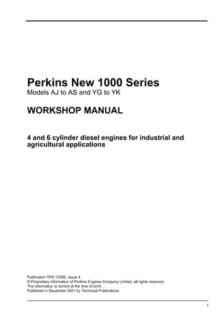
- 16. 1 2 Workshop Manual, TPD 1350E, Issue 4 New 1000 Series Engine views A0378N A0379 This document has been printed from SPI². Not for Resale
- 17. 1 Workshop Manual, TPD 1350E, Issue 4 3 New 1000 Series Engine identification The Perkins New 1000 Series engines have been designed for industrial and agricultural applications. There are both four and six cylinder engines, each of which will have three basic engine types, naturally aspirated, turbocharged and turbocharged with an intercooler. In this workshop manual, the different engine types are indicated by their code letters. These are the first two letters of the engine number as indicated below: The correct identification of the engine is by the full engine number. The engine number is stamped on a label which is fastened to the left side (A2) of the cylinder block. An example of an engine number is: AK80920*U510256B* The components of the engine number are as follows: AK80920*U510256B* Continued AJ Four cylinder, naturally aspirated AK Four cylinder, turbocharged AM Four cylinder, turbocharged and intercooled AP Four cylinder, naturally aspirated, belt driven coolant pump AQ Four cylinder, turbocharged, belt driven coolant pump AR Four cylinder, naturally aspirated, 103 mm cylinder bore AS Four cylinder, naturally aspirated, belt driven coolant pump, 103 mm cylinder bore YG Six cylinder, naturally aspirated YH Six cylinder, turbocharged YJ Six cylinder, charge cooled, air to air YK Six cylinder, turbocharged and intercooled AK Model code number 80920 Build list number U Built in the UK 510256 Engine serial number B Year of manufacture 21 3 A A0043 This document has been printed from SPI². Not for Resale
- 18. 1 4 Workshop Manual, TPD 1350E, Issue 4 New 1000 Series Date letters for engines start from the 1st of January each year. To comply with the new emissions legislation that engines built before 1st April 1999 can be clearly identified from those built after this date, a new letter has been used from the 1st of April 1999. The date letters used are as follows: From the 1st of January 1999 to the 31st of March 1999 the date letter is E. From the 1st of April 1999 to the 31st of January 1999 the date letter is F. If you need parts, service or information for your engine, you must give the complete engine number to your Perkins distributor. If there is a number in the area of the label marked TPL No, then this number must also be given to your Perkins distributor. Other identification labels fitted to the engine include: An emissions legislation label (A3) fitted to the side of the cylinder block. A label (A1) with the fuel injection pump part numbers. If a short engine has been fitted in service two engine serial numbers and a TPL number are stamped on the engine serial number pad (B3). Examples of the serial numbers are shown in (B). If parts for the short engine are needed in service, use the serial number (B4). If parts which were moved from the original engine to the short engine are needed, use the serial number (B1) and the TPL number (B2). 21 3 A A0043 4 1 2 3 B A0045 AK80920*U510256B* AJ39770 TPL No 212 This document has been printed from SPI². Not for Resale