SlideShare a Scribd company logo
1 of 23
Download to read offline
Copyrighted Material
Intended for CLARK dealers only
Do not sell or distribute
SM498S
CGC, CGP, CDP 20-30
Shop Manual
VOLUME 1 OF 2, GROUPS 00 - 03
Copyrighted Material
Intended for CLARK dealers only
Do not sell or distribute
Truck Models Covered by this Manual
This manual consists of a “base” module that pertains to
ail Genesis models and other modules that pertain only to
You may, however, purchase specific modules and expand
specific models. Manuals shipped with the truck contain
your manual to fully cover multiple models. To do so,
the base module and the modules specific to the purchased
order the desired modules as you would any other Clark
part.
truck.
Arrangement and Use of this Manual
Clark armuges parts and service procedures by standard-
ized Groups. In this manual, Groups are similar to “chap-
ters.” Groups are listed in the indexes on the next page.
Each Group begins with a table of contents that shows the
You can quickly locate a specific point in the manual by
using the headers and footers that appear on every Section
page. The following illustration points out these areas.
Sections contained within the Group. Lengthy Sections
also begin with a table of contents.
Each Group and Section has an identifying name and
number, or “ID.”
Each page also has a unique ID The page ID consists of
three numbers separated by hyphens. The three numbers
represent the Group number, the Section number, and the
page number. For example, “00-1-2” on the lower comer
ns In
Section ID
/
Mania,ID

Section ID
of the page indicates Group 00, Section 1,Page 2.
The Group number sometimes has a letter or letters added
to it in parentheses if one or more variations of the Group This manual is intended for the use of trained service
exist. For example, if the truck has a standard transaxle, personnel. Please read Group SA, “Safe Maintenance,”
Group 06 is expressed as “06(S);” if the truck has a hydro- and the Operator’s Manual before working on or operat-
static transmission, Group 06 is expressed as “06(H).” ing the truck.
0 Copyright Clark Material Handling 1994 SM 598,Oct ‘94
Copyrighted Material
Intended for CLARK dealers only
Do not sell or distribute
CONTENTS
Group SA. SafeMaintenance
Group PS. Periodic Service
Group 00. Engines
Group 01. Cooling System
Groupo2.Fuel System
Group 03. Air Induction System
Group 06. Transmission
Group 12. Ignition System
Group w. Instrument Pod
Group 14. Electrical System
Contents of this Manual
Group Index
Group 34. Uprights
Y
Group 22.
Group 23.
Group 25.
Group 26.
Group 29.
Group 30.
Group 32.
Group 34.
Group 38.
Group 40.
Alphabetical Index
(SEE NEXT PAGE)
Pictorial Index
Wheels and Tires
Brake System
Steering Column and Gear
Steer Axle
Hydraulic Pump, Sump, and Filters
Hydraulic Control Valve/Lii Circuit
Tilt Cylinders
uprights
Counterweight, Sheet Metal, & Chassis
Specifications
Group 32. Tilt Cylinders
 n n /Group 06. Transmission
II / Group 23. Brake/Inching System
SM 598, Apr ‘96 Contents-l
Copyrighted Material
Intended for CLARK dealers only
Do not sell or distribute
GROUP SA
GROUP SA
SAFE MAINTENANCE
Safety ............................................................................... Section 1
Lifting, Jacking, and Blocking the Truck ..................... Section 2
Towing .............................................................................. Section 2
SM 598, OCT ‘94 Safe Maintenance
Copyrighted Material
Intended for CLARK dealers only
Do not sell or distribute
CMRK Group SA, Safe Maintenance
Section 1. Safety
SafetySigns and Messages Safe Maintenance Practices
Safety signs and messages in this manual and on the lii
truck provide instructions and identify specific areas where
potential hazards exist and special precautions should be
taken. Be sure you know and understand the meaning of
these instructions, signs, and messages. Damage to the
truck, death, or serious injury to you or other persons may
result if these messages are not followed.
NOTE
This message is used when special informa-
tion, instructions or identification is re-
quired relating to procedures, equipment,
tools, pressures, capacities, and other spe-
cial data.
The following instructions have been prepared from cur-
rent industry and government safety standards applicable
to industrial truck operation and maintenance. These rec-
ommended procedures specify conditions, methods, and
accepted practices that aid in the safe maintenance of in-
dustrial trucks. They are listed here for the reference and
safety of all workers during maintenance operations. Care-
fully read and understand these instructions and the spe-
cific maintenance procedures before attempting to do any
repair work.
When in doubt of any maintenance procedure, please con-
tact your local Clark dealer.
1.
IMPORTANT
Powered industrial trucks can become hazardous if
maintenance is neglected. Therefore, suitable mainte-
nance facilities, trained personnel, and procedures
must be provided
This message is used when special precau-
tions should be taken to ensure a correct
action or to avoid damage to, or malfunc-
tion of, the truck or a component.
2. Maintenance and inspection of all powered industrial
trucks shall be done in conformance with the
manufacturer’s recommendations.
3.
A CAUTION
This message is used as a reminder of safety
hazards that can result in personal injury
if proper precautions are not taken.
4.
A scheduled planned maintenance, lubrication, and
inspection program shah be followed.
Only trained and authorized personnel shah be permit-
ted to maintain, repair, adjust, and inspect industrial
trucks. Work should be performed in accordance with
the manufacturer’s specifications.
A WARNING
This message is used when a hazard exists
that can result in injury or death if proper
precautions are not taken.
5.
6.
A DANGER
This message is used when an extreme haz-
ard exists that can result in injury or death
or serious injury if proper precautions are
not taken.
Properly ventilate work area vent exhaust fumes, and
keep shop clean and floor dry.
Avoid fire hazards and have fire protection equipment
present in the work area Do not use an open flame to
check for level or leakage of fuel, electrolyte, or
coolant. Do not use open pans of fuel or flammable
cleaning fluids for cleaning parts.
7.
The above terms have been adopted by Clark Material
Handling Company. The same terms may be used in differ-
ent context in service literature supplied directly or indi-
rectly by vendors of truck components.
Before starting work on truck:
a. Raise drive wheels off of floor or disconnect
power source and use blocks or other positive
truck positioning devices.
b. Disconnect battery before working on the electri-
cal system.
8. Before working on engine fuel system of gasoline- or
diesel-powered trucks, be sure the fuel shut-off valve
is closed.
SM 598,Oct ‘94 Safety l SA-l-1
Copyrighted Material
Intended for CLARK dealers only
Do not sell or distribute
Group SA, Safe Maintenance EUIRK
9.
10.
11.
12.
13.
14.
15.
16.
17.
18.
Operation of the truck to check performance must be
conducted in an authorized, safe, clear area.
Before starting to drive truck:
a. Be in operating position.
b. Be sure parking brake is engaged.
c. Put direction control in neutral.
d. Start engine.
e. Check functioning of direction and speed con-
trols, steering, brakes, warning devices, and any
load handling attachments.
19.
20.
21.
Modifications and additions that affect capacity and
safe truck operation must not be done without the
manufacturer’s prior written approval. Capacity, op-
eration and maintenance instruction plates, tags, or
decals must be changed accordingly. This is an OSHA
requirement.
Care must be taken to assure that all replacement parts,
including tires, are interchangeable with the original
parts and of a quality at least equal to that provided in
the original equipment. Parts, including tires, are to be
installed per the manufacturer’s procedures. Always
use genuine CLARK or CLARK-approved parts.
Before leaving truck
a. Stop truck.
b. Put directional control in neutral.
c. Apply the parking brake.
d. Stop the engine by turning off the ignition circuit.
e. Put blocks at the wheels if truck is on an incline.
Brakes, steering mechanisms, control mechanisms,
warning devices, lights, governors, guards, safety de-
vices, and frame members must be carefully and regu-
larly inspected and maintained in a safe operating
condition.
Use special care when removing heavy components
from the truck, such as counterweight, seat deck,
upright, etc. Be sure that lifting and handling equip-
ment is of the correct capacity and in good condition.
Also, this removal may upset the stability of the truck.
The frame must always be safely blocked for major
component removal.
NOTE
Special trucks or devices designed and approved for
hazardous area operation must receive special atten-
tion to ensure that maintenance preserves the original,
approved, safe-operating features.
You should also be familiar with additional
operating and maintenance safety instruc-
tions contained in the following publica-
tions:
Fuel systems must be checked for leaks and condition
of parts. Extra special consideration must be given in
the case of a leak in the fuel system. Action must be
taken to prevent the use of the truck until the leak has
been corrected.
ANSVASMEB56.1- 1988Operator Control-Industrial Tow
Tractors (Safety Standard For Powered Industrial Trucks).
Published by: Society of Mechanical Engineers, United
Engineering Center, 345 E. 47th Street, New York, NY
10017.
The truck manufacturer’s capacity, operation, and
maintenance instruction plates, tags, or decals must be
maintained in legible condition.
NFPA 505-1982: Fire Safety Standard for Powered Indus-
trial Trucks: Type Designations, Areas of Use, Mainte-
nance and Operation. Available from: National Fire
Protection Assoc., Inc., Batterymarch Park, Quincy, MA
02269.
Batteries, motors, controllers, limit switches, protec- General Industrial Standards, OSHA 2206: OSHA Safety
tive devices, electrical conductors, and connections and Health Standards (29 CFR 1910), Subpart N-Materials
must be inspected and maintained in conformance Handling and Storage, Section 1910.178 Powered Indus-
with good practice. Special attention must be paid to trial Trucks. For sale by: Superintendent of Documents,
the condition of electrical insulation. U.S. Government Printing Office, Washington, DC 20402.
To avoid injury to personnel or damage to the equip-
ment, consult the manufacturer’s procedures inreplac-
ing contacts on any battery connection.
Industrial trucks must be kept in a clean condition to
minimize fire hazards and helpin the detection of loose
or defective parts.
SA-1-2 l Safety SM 598,Oct ‘94
Copyrighted Material
Intended for CLARK dealers only
Do not sell or distribute
CMRK Group SA, Safe Maintenance
Lifting, Jacking, and Blocking
3
Safe Parking ....................................................................................................................................&
Lifting, Jacking, and Blocking Points ..........................................................................................2
Raising Drive Wheels Off Floor ....................................................................................................2
Raising Truck with A Hoist ..........................................................................................................3
Blocking the Upright in Raised Position ......................................................................................4
Raising Rear of Truck ...................................................................................................................4
Section 2.
Raising Entire Truck .....................................................................................................................5
Shipping Tie-Down Instructions ...................................................................................................6
A WARNING
Lifting or jacking any large piece of equipment such as your fork truck presents
obvious hazards. It must be done with great care and forethought. Consult the
truck weight tabulations in Group 40, “Specifications” to ensure that your
lifting equipment is of adequate capacity.
SM 598,Oct ‘94 Lifting, Jacking, and Blocking l SA-2-1
Copyrighted Material
Intended for CLARK dealers only
Do not sell or distribute
Group SA, Safe Maintenance CUlRK
Safe Parking
Before working on truck:
1. Park truck on a hard, level, and solid surface, such as
a concrete floor with no gaps or breaks.
2. Put upright in vertical position and fully lower the
forks or attachment.
3. Put all controls in neutral. Turn key switch OFF and
remove key.
4. Apply the parking brake and block the wheels.
A WARNING
Defective equipment can cause accidents.
All tools and lifting equipment must be in
good condition, meet the load capacity re-
quirements and have OSHA labels when
required. Tools with defects can have fail-
ures causing severe injury or death.
Lifting,Blocking,andJackingPoints
Use the following illustration to locate general lifting, block-
ing, and jacking points on the truck. Read the procedures
for raising, blocking, or jacking specific components of the
truck to make sure you understand the correct, safe proce-
dures.
‘hnder Steer L Under Frame L Under Upright
Axle Frame
Mount
A WARNING
Do not attempt to lift the truck by the over-
head guard or the counterweight. Severe
injury may result and the truck can be
damaged.
RaisingDriveWheelsOff Floor
This procedure uses the upright as a lever to lift the drive
wheels off the floor and prevent accidents due to inadvert-
ent powering of the drive wheels.
Park truck safely as described in “Safe Parking.” Block
steer wheels.
Be sure upright trunnion bolts are tight. Bolt torques
must be 75-80 Nom (55-59 ft-lb).
Start the engine. Tilt the upright fully back. Adjust
upright height as necessary to put blocking underneath
the lower end of the upright.
Put a solid 100 x 100 mm (4 x 4 in) hardwood block
under the front section of each upright rail. Put a 3-6
mm (.125-.250 in) steel plate on top of each block.
5. Tilt upright fully forward. This raises the drive wheels
off the floor. Release the tilt control lever and turn
engine OFF.
SA-2-2 . Lifting, Jacking, and Blocking SM 598,Oct ‘94
Copyrighted Material
Intended for CLARK dealers only
Do not sell or distribute
ClRRK Group SA, Safe Maintenance
6. Insert blocking under the frame behind the drive
wheels or slip wheel cradles under the drive wheels. If
using blocking, check for safe clearance between drive
wheels and floor and blocks.
7.
8.
NOTE
When forks are raised as in illustration
above, use shop rags, paper, or bright tape
on fork tips to signal the danger of trip-
ping.
Check for stable condition of the truck. Be sure that the
blocks are located securely under the truck frame
before operating the drive or working on truck.
Lower the drive wheels to the floor and remove the
blocks by reversing the above procedure.
RaisingTruck with A Hoist
When suitable equipment is available, the front of the truck
may be raised by means of a hoist, with wheel cradles
placed under the wheels or blocking placed under the frame.
n ! CAUTION
When lifting the front of the truck watch
truck for signs of lateral instability. It may
tip sideways. You may have to support or
guide the side of the truck or overhead
guard to prevent tipping.
1. Park truck safely as described in “Safe Parking.” Block
rear steer wheels.
2. Check trunnion bolts to make sure they are tightened to
correct torque. Bolt torques must be 75-80N.m (55-59
ft-lb).
3. To raise the front of the truck using the upright, spread
two chains on the outer rail tiebar of the upright.
4.
A WARNING
Chain and hoist used to lift truck should be
checked to make sure they are of safe Iift-
ing capacity. See the truck data plate for
information.
Slowly lift truck and lower drive wheels onto the
cradles or place blocking under frame prop points.
5. When maintenance work is completed, lower the truck
to the floor by reversing the lifting procedure. Check to
be sure no tools or equipment are under the truck or
wheels.
SM 598,Oct ‘94 Lifting, Jacking, and Blocking l SA-2-3
Copyrighted Material
Intended for CLARK dealers only
Do not sell or distribute
Group SA, Safe Maintenance ClmK
Blocking the Upright In Raised Position
This procedure is used to safely provide clearance for
access from the front of truck to components on or near the
drive axle. Illustrations show upright with forks removed
however, fork removal is not necessary
1.
2.
3.
4.
5.
6.
Park truck safely as described in “Safe Parking.”
Put blocks in front of and behind drive wheels.
Put wooden support blocks conveniently near upright
rails before raising the upright. Use two 100 x 100 mm
(4 x 4 in) hardwood blocks or equal, of about 300 x 300
mm (12 in) and 600 x 600 mm (24 in) length.
NOTE
For standard uprights, block may need
length cut to suit. For triple stage uprights,
the carriage may be blocked up, as shown.
Start engine and raise the upright carriage.
Hold the taller block against inner rail and lower the
upright until carriage rests on block.
Outer
Rail
Hold the shorter block against the outer rail and lower
the upright until inner rail rests on the block.
Outer
Rail
II II ”Al/II/le Carriage
.*II I
Short
Block
7. Reverse the procedure to remove blocking.
RaisingRear of Truck
The truck may be raised at the rear by jacking and blocking
under the center of the frame member at either the front or
rear steer axle mounting, or under the center section of the
steer axle.
Refer to truck data plate for truck weights.
1.
A WARNING
An incorrectly installed counterweight can
move or fall unexpectedly. Never lift or
block a truck using the counterweight. Fail-
ure to follow procedures outlined in this
manual can result in injury or death.
Park truck safely as described in “Safe Parking.” Put
blocks at front and rear of drive wheels.
SA-2-4 l Lifting, Jacking, and Blocking SM 598,Oct ‘94
Copyrighted Material
Intended for CLARK dealers only
Do not sell or distribute
ClRRK Group SA, Safe Maintenance
2. Put a floor jack under the steer axle mounting frame
member, centered between the two wheels.
A WARNING
Never lift the truck by the counterweight.
3.
4.
NOTE
If there is insufftcient clearance under
frame for your jack, the truck may fmt be
driven onto shims, such as 25 x 150 x 300
mm (1 x 6 x 12 in) pieces of board, to
increase the truck frame underclearance.
Raisethetruckonlyashighasnecessary toperformthe
maintenance work
Put blocks at both sides of the truck, fully under the
frame main side structure. Put theblocks in front of but
close to the counterweight and steer wheels for best
truck stability.
Put equal blocks under each sideofthetruck to provide
a level working position.
5. Lower the truck onto the blocks and remove the jack.
n ! CAUTION
Before performing any maintenance, check
the truck for stabilitY on the blocks.
6. When maintenance work is completed, lower the rear
of truck to the floor by reversing the above procedure
and lowering each side of the truck 50 mm (2 in) at a
time:
l Put jack under frame and raise truck
l Carefully remove blocks and lower truck.
l Remove jack and blocks from drive wheels.
RaisingEntireTruck
Refer to truck data plate for truck weights.
1.
2.
Park truck safely as described in “Safe Parking.”
Lower upright fully.
If necessary, drive truck onto boards to increase
undercLearance.
A WARNING
SIDE-TO-SIDE TIPOVER. When jacking
side of truck, be sure upright is lowered
fully and do not raise one side of the truck
more than about 50 mm (2 in) higher than
the other, to avoid tipping truck over later-
ails*
END-TO-END TIPOVER. If the upright
and &ansaxle are removed while the truck
is blocked up, the truck will tip backwards
due to the heavy counterweight. Both up-
right and counterweight must be removed
before attempting to raise the truck for
transaxle removal. The back of the truck
must be supported by blocking under the
steer axle to prevent movement.
The reverse is also true. If the counter-
weight is removed while the truck is up on
blocks, the weight of the upright and
transaxle will cause the truck to tip on the
front blocks and fall forward.
SM 598,Apr ‘96 Lifting,Jacking,and Blocking l SA-2-5
Copyrighted Material
Intended for CLARK dealers only
Do not sell or distribute
Group SA, Safe Maintenance emu
3. Put the jack under side frame near the center of the
truck.
4.
5.
IMPORTANT
Be sure to put the jack squarely and fully
under the main side structure of the frame.
Do not put the jack under the outer covers
which enclose the fuel and hydraulic sump
tanks.
Carefully raise the truck one sideat a time, only as high
as necessary to do the maintenance work and not more
than a maximum of 150 mm (6 in) total.
Putblocks under the sideframe, at each side ofthejack.
Spread the blocks close to the steer and drive wheels
for maximum stability.
6.
7.
If using one jack, lower the truck onto the blocks and
move the jack to the opposite side. Repeat the lifting
procedure.
Put the same size blocks under each side of the truck so
it will be level.
0! CAUTION
Before performing any maintenance work,
check the truck for stable condition on the
blocking.
When maintenance work is completed, lower the en-
tire truck to the floor by reversing thelifting procedure.
Lower the truck one side at a time, while carefully
removing the blocks. Check to be sure no tools or
equipment are under the truck or wheels.
NOTE
Depending on jack height, shims under the
tires may be needed for clearance to allow
removal of jack.
Shipping Tie-Down Instructions
Front of Truck
a. With Upright and Carriage Installed
l Lower the carriage fully.
l Put a tie down (e.g., chain) between the carriage
fork bars.
b. Without an Upright and Carriage Installed
l Put a chain across the truck floor plate. Protect
truck from chain damage by using covered chain
or protective material under the chain at contact
points.
Rear of Truck
l Attach the tie down to pocket in bottom of coun-
terweight.
SA-2-6 l Lifting, Jacking, and Blocking SM 598,Oct ‘94
Copyrighted Material
Intended for CLARK dealers only
Do not sell or distribute
Group 25, Steering Column and Gear CIARK
Disassembly
Cleanliness is extremely important when repairing a steer-
ing gear. Work in a clean area. Before disconnecting lines,
clean port area of unit thoroughly. Use a wire brush to
remove foreign material and debris from around exterior
joints of the unit.
NOTE
Although not all illustrations show the unit
in a vise, it is recommended to keep the
unit in the vise during disassembly. Follow
the clamping procedures explained
throughout the text.
Meter (Gerotor) End
1. Clamp unit in vise, meter end up. Clamp lightly on
edges of mounting area, as shown. Use protective
material on vise jaws. Do not over-tighten jaws.
Remove meter (gerotor). Be careful not to drop star
(rotor).
Rotor
Remove seal from meter.
Remove drive spacer(s).
Remove drive.
,e Capscrew
.
1
2. Remove capscrews. Control End
Sial Cap Screw
3. Remove end cap.
4. Remove seal from end cap.
cer
are
9. Remove spacer plate.
10. Remove seal from housing.
11. Remove housing from vise and place on a clean soft
cloth to protect surface finish. Use athin-bladed screw-
driver to pry retaining ring from housing.
25-5-2 l Steering Gear Overhaul SM 598,Oct ‘94
Copyrighted Material
Intended for CLARK dealers only
Do not sell or distribute
emK Group 25, Steering Column and Gear
12. Place assembly so shaft is horizontal. Rotate spool and
sleeve until pin is horizontal. Push spool and sleeve
assembly forward with your thumbs just far enough to
free seal gland bushing from housing. Remove bush-
ing.
Seal
Gland
Bushing
13. Remove quad ring seal from seal gland bushing.
Dust Seal
/
_. -
14. Use a thin-bladed screwdriver to pry dust seal from
seal gland bushing. Do not damage bushing.
15. Remove two bearing races and the needle thrust bear-
ing from spool and sleeve assembly.
Needle Bearing
Thrust
Bearing
Race
Bearing/w
16. Remove spool and sleeve assembly from cap (14-hole)
end of housing.
Pin
17.
18.
Push pin from spool and sleeve assembly.
Push spool partially from control end of sleeve, then
remove six centering springs from spool carefully by
hand. Note their position in the unit before they are
removed.
19. Push spool back through and out of sleeve. Rotate
spool slowly when removing from sleeve.
20. Remove seal from housing.
(Not used on ’ C;“;k
t
 ‘Check
units with Check Ball
integral column) Seat 7/16” Seal Ball Retainer
21.
22.
Remove set screw from housing.
Screw a l/8-inch-24 NC machine screw into end of
check ball seat. Then pull on screw with pliers to lift
seat out of housing.
23. Remove two seals from check valve seat.
24. Tip housing to remove check ball and check ball
retainer.
IMPORTANT
Do not bind spool and sleeve in housing.
Rotate spool and sleeve assembly slowly
when removing from housing.
SM 598,Oct ‘94 Steering Gear Overhaul l 25-5-3
Copyrighted Material
Intended for CLARK dealers only
Do not sell or distribute
Group 25, Steering Column and Gear ElRRK
Parts Inspection
Inspect all parts for damage, cracks, broken parts, damaged
threads, corrosion or erosion of surfaces, worn spots, nicks
or scratches.
Check all mating surfaces. Replace any parts that have
scratches or burrs that could cause leakage. Discard all old
seals and replace with new ones.
Clean all metal parts in clean solvent. Blow dry with air. Do
not wipe dry with cloth or paper towel because lint or other
matter can get into the hydraulic system and cause damage.
Do not use a coarse grit or try to file or grind these parts.
If parts are left exposed, cover them with a clean cover to
prevent airborne dust from collecting on them.
Reassembly
Refer to Service Parts Book when ordering replacement
parts. A good service policy is to replace all old seals with
new seals at overhaul.
NOTE
Lubricate all seals (with exception of new
quad ring seal) with clean petroleum jelly
such as Vaseline.
Do not use excessive lubricant on seals for
meter (gerotor) section.
Make sure all parts are clean and free of
dust. Before assembly, lightly coat all in-
ternal metal parts with oil.
Control End
1. Use a needle-nosed pliers to lower check ball retainer
into check valve hole of housing. Make sure retainer is
straight (not tilted on edge) in housing.
e-- Set Screw ( Not Used on
Units with Integral Column -
See Figure 12A 1
Check Ball Seat
.Seal 0
” Seal 0 3.9
&!z
0 4
e 4m
Check Ball
Check Ball
Retainer
(Standard Steering
Figure 12 Control Unit)
2. Install check ball in housing.
3. Lubricate 5/8-inch diameter seal and 7/16-inch diam-
eter seal. Install seals on check ball seat, as above.
4.
5.
6.
7.
Lubricate check ball seat and seals thoroughly before
installing seat in housing. When installing seat do not
twist or damage seals. Install check ball seat in hous-
ing; insert open end of seat first. Push check ball seat
to bottom of hole.
Install set screw. Use a 5/16-inch Allen wrench to
torque set screw to 11 Nom (100 in-lb; 8.3 ft-lb). To
prevent interference of parts, make sure top of set
screw is slightly below housing mounting surface.
Assemble spool and sleeve carefully so that the spring
slots line up at the same end. Rotate spool while sliding
parts together. Some spool and sleeve sets have iden-
tification marks; align these marks. Test for free rota-
tion. Spool should rotate smoothly in sleeve with
finger tip force applied at splined end.
Bring spring slots of both parts in line and stand parts
on end of bench. Insert spring installation tool (avail-
able as Part No. 6000057) through spring slots of both
parts. Position three pairs of centering springs (or two
sets of 3 each) on bench so that extended edge is down
and arched center section is together. In this position,
insert one end of entire spring set into spring installa-
tion tool, as shown.
On those units which use the low torque centering
springs, there are two pairs of centering springs (or two
sets of each) and one pair (two) spring spacers. The
spring spacers are installed together between the two
sets of centering springs. The installation procedure is
the same as that used on the standard (three pairs of
centering springs) units.
25-S-4 l Steering Gear Overhaul SM 598,Oct ‘94
Copyrighted Material
Intended for CLARK dealers only
Do not sell or distribute
CWRK Group 25, Steering Column and Gear
8.
9.
10.
11.
12.
Compress extended end of centering spring set and
push into spool sleeve assembly withdrawing installa-
tion tool at the same time.
Center the spring set in the parts so that they push down
evenly and flush with the upper surface of the spool
and sleeve.
Install pin through spool and sleeve assembly until pin
becomes flush at both sides of sleeve.
Pin
Position the spool and sleeve assembly so that the
splined end of the spool enters the 1Chole end of
housing first.
IMPORTANT
Be extremely careful that the parts do not
tilt out of position while being installed.
Push parts gently into place with slight ro-
tating action; keep pin nearly horizontal.
Push the spool assembly entirely within the
housing bore until the parts are flush at the
meter end or 16hole end of housing. Do
not push the spool assembly beyond this
point to prevent the cross pin from drop-
ping into the discharge groove of the hous-
ing. With the spool assembly in this flush
position, check for free rotation within the
housing by turning with light finger tip
force at the splined end.
Place housing on clean, lint free cloth. Install 2-1/8-
inch diameter seal in housing.
13. Install two bearing races and the needle thrust bearing
in the order shown.
Needle
14.
15.
Install I-l/4-inch diameter dust seal in seal gland
bushing; flat or smooth side of dust seal must face
down towards bushing.
Install dry quad ring seal in seal gland bushing. Smooth
seal in place with your finger. Do not use any seal that
falls freely into pocket of bushing. Seal should not
“fall” into place but should require light force to seat.
Seal
Gland -
Bushing
(with seals)
Retaining
Ring
SM 598,Oct ‘94 Steering Gear Overhaul l 25-5-5
Copyrighted Material
Intended for CLARK dealers only
Do not sell or distribute
Group 25, Steering Column and Gear CUIRK
16. Install seal gland bushing over the spool end with a
twisting motion. Tap the bushing in place with arubber
hammer. Make sure the bushing is flush against the
bearing race.
On those units which use the Teflon seal, install the
Teflon back-up ring into the recess cut into the seal
gland bushing. Install the Teflon seal over the spool
end, then carefully install the seal gland bushing over
the spool end using a rotary motion.
NOTE
The seal gland bushing which is used with
the Teflon seal is not the same as the seal
gland bushing used with the standard quad-
ring seal. The seal gland bushing with the
Teflon seal has an identification groove cut
into the outer diameter of the bushing. The
grooved bushings can only be used with the
Teflon seals and the non-grooved bushings
used only with the quad-ring seals.
Teflon Seat
17. Install retaining ring in housing. After installing ring,
tap on ring or pry with screwdriver around entire
circumference of ring to properly seat ring in groove.
Meter (Gerotor) End
18. Clamp housing in vise, as shown. Clamp lightly on
edges of mounting area. Do not overtighten jaws.
NOTICE
Check to ensure that the spool and sleeve
are flush or slightly below the surface of
the housing.
IMPORTANT
Clean the upper surface of the housing by
wiping with the palm of clean hand. Clean
each of the flat surfaces of the meter sec-
tion parts in a similar way when ready for
reassembly. Do not use cloth or paper to
clean surfaces.
19. Install 3-inch diameter seal in housing.
- Seal
20.
21.
Install spacer plate. Align bolt holes in spacer plate
with tapped holes in housing.
Rotate spool and sleeve assembly until pin is parallel
with port face. Install drive, making sure you engage
drive with pin.
Spacer Plate
25-5-6 l Steering Gear Overhaul SM 596,Oct ‘94
Copyrighted Material
Intended for CLARK dealers only
Do not sell or distribute
ClClRU Group 25, Steering Column and Gear
24. Install drive spacer(s) when used, in meter.
22. Install 3-inch diameter seal in meter (gerotor).
23. With seal side of meter toward spacer plate, align star
valleys on drive. Note the parallel relationship of
reference lines A, B, C, and D in figure. Align bolt
holes without disengaging meter from drive. Be sure
star has engaged drive spline in position shown.
IMPORTANT
Failure to properly install drive and pin
may cause unit to self steer.
NOTE
To assure proper alignment, mark spline
end of drive shaft with a line parallel to slot
on other end, before installing.
Meter (Gerotorl Star VakV
Pin Port Face
cu. m/rev. Displ. Unit
equires 2 Spacers
25.
26.
27.
28.
Install 3-inch diameter seal in end cap.
Install end cap on gerotor, and align holes.
Install 7 &y cap screws in end cap. Pretighten.screws
to initial torque of 17 I+m (150 in-lb), then torque
screws to final torque of 31 N*m (275 in-ib) in the
sequence shown.
Inspect the assembly to be sure all parts have been
installed and fasteners correctly installed and tight-
ened.
(Reprint courtesy of EATON Corporation)
SM 598,Oct ‘94 Steering Gear Overhaul l 25-5-7
Copyrighted Material
Intended for CLARK dealers only
Do not sell or distribute
GROUP 26
GROUP 26
STEER AXLE
Steer Axle Specifications and Description .................... Section 1
Steer Axle Wheel Bearing Maintenance and Adjustment.. ........
................................................................................... Section 2
Steer Axle Removal and Replacement .......................... Section 3
Steer Axle Overhaul ........................................................ Section 4
Steer Cylinder Removal and Replacement ................... Section 5
Steer Cylinder Overhaul ................................................ Section 6
SM 598,Oct ‘94 Steer Axle
Thank you very much for
your reading. Please Click
Here. Then Get COMPLETE
MANUAL. NO WAITING
NOTE:
If there is no response to
click on the link above,
please download the PDF
document first and then
click on it.
Copyrighted Material
Intended for CLARK dealers only
Do not sell or distribute
clmu Group 26, Steer Axle
Steer Axle
Specifications
Cushion-Tire
Steering System Relief Pressure Setting:
(1200-1300 psi).
Section 1.
Specifications and Description
8270-8960 kPa
Steer Cylinder Type: Double-acting, piston-type.
Turning Arc: 83” maximum inside turning angle; 60” maxi-
mum outside turning angle.
Pneumatic-Tire
Steering System Relief Pressure Setting: 8970 kPa (1300
psi)
Steer Cylinder Type: Double-acting, piston-type
Turning Arc: 75”maximum inside turning angle; 54” maxi-
mum outside turning angle.
Bearing Grease: Grade No. 2 EP multi-purpose grease,
Clark Part MS-107C.
Fastener Torques
Steer Axle Mounting Bolts: 170-190 Wm (125-140 ft-lb)
Cylinder to Axle Mounting Bolts: 280-320 Wm (205-234.5
ft-lb)
Steering Link to Steering Knuckle Nuts: 135-150 Nom (9%
110 ft-lb)
Steer Knuckle King Pin Castle Nuts: See installation proce-
dures in Section 4, “Steer Axle Overhaul.”
Service intervals
Steering Linkage Inspection and Lubrication: Every 50-
250 hours and each PM.
Steer Wheel Bearing Inspection and Lubrication: Every
500 hours of operation.
Steer Cylinder Seals Leakage Check: Every 50-250 hours
and each PM.
Steer Axle Mounting Inspection: Every 50-250 hours and
each PM.
Power Steering Relief Pressure Check: Every year or 2000
hours of operation.
Description
The steer axle has the steer cylinder, steer knuckles, and
steering links mounted on it. All these components can be
removed, serviced, and replaced.
The steering gear (steering control unit) at the base of the
steering column directs hydraulic fluid to one end or the
other of the steer cylinder to pivot the steer wheels.
The steer axle is bolted to the truck frame. The steer cylin-
der is connected to the steering knuckles by steer links.
Mounting trunnions allow the axle to tilt independently of
the truck and “silent” mounts cushion the axle on the
trunnions.
All bearings used in the steer axle linkage have lubrication
fittings and are serviceable. Axle removal, replacement,
and service for all components, including overhaul of the
steer cylinder, is explained in the Sections for this Group.
SM 598, Ott ‘94 Steer Axle Specifications and Description l 26-l-l
Copyrighted Material
Intended for CLARK dealers only
Do not sell or distribute
Group 26, Steer Axle CIRRK
Steer -
Cylinder
Axle
Mounting
frunnion
Silent
Mount
Steer Axle 7
Steer
Steer
Knuckle
‘-ink
Steer Axle and Mounting - Cushion-Tire Axle
Steer -
Cylinder
Mounting
Trunnion
Steer
Knuckle
Steering J
Link
Steer Axle and Mounting - Pneumatic-Tire Axle
26-1-2 l Steer Axle Specifications and Description SM 598,Oct ‘94
Copyrighted Material
Intended for CLARK dealers only
Do not sell or distribute
CHIC Group 26, Steer Axle
Section 2.
Steer Axle Wheel
Bearing Maintenance and Adjustment
Wheel Bearing Check ...................f................................................................................................ 1
Wheel Bearing Lubrication ...........................................................................................................1
Bearing Disassembly ....................................................................................................................... 2
Bearing Reassembly ......................................................................................................................... 3
Wheel Bearing Adjustment ...........................................................................................................4
IMPORTANT
Before removing any component for overhaul, make sure the correct repair
parts, seals, and gasket sets are available.
A CAUTION
SAFE PARKING. Before working on truck:
Park truck on a hard, level, and solid
surface, such as a concrete floor with no
gaps or breaks.
Put upright in vertical position and fuBy
lower the forks or attachment.
Put ah controls in neutral. Turn key switch
OFF and remove key.
Apply the parking brake and block the
wheels.
Wheel Bearing Check
A wheel bearing check should be performed about every
500 hours of operation or three or four times a year. Wheel
bearings need adjustment only after 2000 hours or as needed.
It is recommended that you clean and repack the bearings
before adjustment. Check hourmeter total hours and refer
to the truck’s PM schedule. See steer wheel bearing
lubrication procedure below.
To check the steer wheel bearings for excessive free play or
looseness:
1. Grasp the wheel with both hands and try to move it by
a rocking motion top-to-bottom.
2. Try to pull it in and out along the wheel spindle.
Watch for excessive free movement in wheel bearings or
steering knuckle bearings. There should be a small amount
of free movement. If the wheel has excessive free move-
ment, the bearings require additional service and/or adjust-
ment.
Wheel Bearing Lubrication
These procedures cover bearing lubrication for the two
types of steer wheels used on the truck; pneumatic-tire
wheels which are mounted on a hub that contains the bear-
ing components and cushion-tire wheels with the bearings
installed in the wheel. Use the procedures to clean, repack
and adjust bearings for both the cushion-wheel and the
pneumatic-tire hub.
Pneumatic-Tire
Wheel Mounting
,CushiFr ,
Steer Axle Knuckle 1 I I
Pneumatic-tire (lef) and cushion-tire (right) wheel-
bearing assemblies.
The bearing components and arrangement are the same for
both the cushion and pneumatic types. Instructions for
repacking/lubricating the bearing components apply to both
types*
SM 588,Oct ‘84 Steer Axle Wheel Bearing Maintenance and Adjustment l 26-2-l

More Related Content

Similar to Clark cgp 20 30 forklift service repair manual

Clark cgc 20 30 forklift service repair manual
Clark cgc 20 30 forklift service repair manualClark cgc 20 30 forklift service repair manual
Clark cgc 20 30 forklift service repair manualfjksekmdme
 
Clark cgc 20 30 forklift service repair manual
Clark cgc 20 30 forklift service repair manualClark cgc 20 30 forklift service repair manual
Clark cgc 20 30 forklift service repair manualdidkkskdmmd1
 
Clark cgc 20 30 forklift service repair manual
Clark cgc 20 30 forklift service repair manualClark cgc 20 30 forklift service repair manual
Clark cgc 20 30 forklift service repair manualfjjsekkdmme
 
Clark CGP 20-30 Forklift Service Repair Manual.pdf
Clark CGP 20-30 Forklift Service Repair Manual.pdfClark CGP 20-30 Forklift Service Repair Manual.pdf
Clark CGP 20-30 Forklift Service Repair Manual.pdffjdkksmemd
 
Clark CDP 20-30 Forklift Service Repair Manual.pdf
Clark CDP 20-30 Forklift Service Repair Manual.pdfClark CDP 20-30 Forklift Service Repair Manual.pdf
Clark CDP 20-30 Forklift Service Repair Manual.pdffjdkksmemd
 
Clark CGC 20-30 Forklift Service Repair Manual.pdf
Clark CGC 20-30 Forklift Service Repair Manual.pdfClark CGC 20-30 Forklift Service Repair Manual.pdf
Clark CGC 20-30 Forklift Service Repair Manual.pdffjdkksmemd
 
Clark cdp 20 30 forklift service repair manual
Clark cdp 20 30 forklift service repair manualClark cdp 20 30 forklift service repair manual
Clark cdp 20 30 forklift service repair manualdidkkskdmmd1
 
Clark cdp 20 30 forklift service repair manual
Clark cdp 20 30 forklift service repair manualClark cdp 20 30 forklift service repair manual
Clark cdp 20 30 forklift service repair manualfjksekmdme
 
Clark cgp 20 30 forklift service repair manual
Clark cgp 20 30 forklift service repair manualClark cgp 20 30 forklift service repair manual
Clark cgp 20 30 forklift service repair manualfjksekmdme
 

Similar to Clark cgp 20 30 forklift service repair manual (9)

Clark cgc 20 30 forklift service repair manual
Clark cgc 20 30 forklift service repair manualClark cgc 20 30 forklift service repair manual
Clark cgc 20 30 forklift service repair manual
 
Clark cgc 20 30 forklift service repair manual
Clark cgc 20 30 forklift service repair manualClark cgc 20 30 forklift service repair manual
Clark cgc 20 30 forklift service repair manual
 
Clark cgc 20 30 forklift service repair manual
Clark cgc 20 30 forklift service repair manualClark cgc 20 30 forklift service repair manual
Clark cgc 20 30 forklift service repair manual
 
Clark CGP 20-30 Forklift Service Repair Manual.pdf
Clark CGP 20-30 Forklift Service Repair Manual.pdfClark CGP 20-30 Forklift Service Repair Manual.pdf
Clark CGP 20-30 Forklift Service Repair Manual.pdf
 
Clark CDP 20-30 Forklift Service Repair Manual.pdf
Clark CDP 20-30 Forklift Service Repair Manual.pdfClark CDP 20-30 Forklift Service Repair Manual.pdf
Clark CDP 20-30 Forklift Service Repair Manual.pdf
 
Clark CGC 20-30 Forklift Service Repair Manual.pdf
Clark CGC 20-30 Forklift Service Repair Manual.pdfClark CGC 20-30 Forklift Service Repair Manual.pdf
Clark CGC 20-30 Forklift Service Repair Manual.pdf
 
Clark cdp 20 30 forklift service repair manual
Clark cdp 20 30 forklift service repair manualClark cdp 20 30 forklift service repair manual
Clark cdp 20 30 forklift service repair manual
 
Clark cdp 20 30 forklift service repair manual
Clark cdp 20 30 forklift service repair manualClark cdp 20 30 forklift service repair manual
Clark cdp 20 30 forklift service repair manual
 
Clark cgp 20 30 forklift service repair manual
Clark cgp 20 30 forklift service repair manualClark cgp 20 30 forklift service repair manual
Clark cgp 20 30 forklift service repair manual
 

More from fjjsieskekfmmse

Kobelco sk500 lc 10 hydraulic excavator (na 2019) service repair manual
Kobelco sk500 lc 10 hydraulic excavator (na 2019) service repair manualKobelco sk500 lc 10 hydraulic excavator (na 2019) service repair manual
Kobelco sk500 lc 10 hydraulic excavator (na 2019) service repair manualfjjsieskekfmmse
 
Kobelco sk500 lc 10 (anz 2019) hydraulic excavator service repair manual
Kobelco sk500 lc 10 (anz 2019) hydraulic excavator service repair manualKobelco sk500 lc 10 (anz 2019) hydraulic excavator service repair manual
Kobelco sk500 lc 10 (anz 2019) hydraulic excavator service repair manualfjjsieskekfmmse
 
Kobelco sk480 lc 8 (hs engine) hydraulic excavator service repair manual
Kobelco sk480 lc 8 (hs engine) hydraulic excavator service repair manualKobelco sk480 lc 8 (hs engine) hydraulic excavator service repair manual
Kobelco sk480 lc 8 (hs engine) hydraulic excavator service repair manualfjjsieskekfmmse
 
Kobelco sk460 8 (hs engine) hydraulic excavator service repair manual
Kobelco sk460 8 (hs engine) hydraulic excavator service repair manualKobelco sk460 8 (hs engine) hydraulic excavator service repair manual
Kobelco sk460 8 (hs engine) hydraulic excavator service repair manualfjjsieskekfmmse
 
Kobelco sk350 lc 10 hydraulic excavator service repair manual
Kobelco sk350 lc 10 hydraulic excavator service repair manualKobelco sk350 lc 10 hydraulic excavator service repair manual
Kobelco sk350 lc 10 hydraulic excavator service repair manualfjjsieskekfmmse
 
Kobelco sk350 lc 8 hydraulic excavator service repair manual
Kobelco sk350 lc 8 hydraulic excavator service repair manualKobelco sk350 lc 8 hydraulic excavator service repair manual
Kobelco sk350 lc 8 hydraulic excavator service repair manualfjjsieskekfmmse
 
Kobelco sk330 10 hydraulic excavator service repair manual
Kobelco sk330 10 hydraulic excavator service repair manualKobelco sk330 10 hydraulic excavator service repair manual
Kobelco sk330 10 hydraulic excavator service repair manualfjjsieskekfmmse
 
Kobelco sk330 8 hydraulic excavator service repair manual
Kobelco sk330 8 hydraulic excavator service repair manualKobelco sk330 8 hydraulic excavator service repair manual
Kobelco sk330 8 hydraulic excavator service repair manualfjjsieskekfmmse
 
Kobelco sk260 lc 10 hydraulic excavator service repair manual
Kobelco sk260 lc 10 hydraulic excavator service repair manualKobelco sk260 lc 10 hydraulic excavator service repair manual
Kobelco sk260 lc 10 hydraulic excavator service repair manualfjjsieskekfmmse
 
Kobelco sk260 lc 8 (hs engine) hydraulic excavator service repair manual
Kobelco sk260 lc 8 (hs engine) hydraulic excavator service repair manualKobelco sk260 lc 8 (hs engine) hydraulic excavator service repair manual
Kobelco sk260 lc 8 (hs engine) hydraulic excavator service repair manualfjjsieskekfmmse
 
Kobelco sk210 lc 10 (for north america) hydraulic excavator service repair ma...
Kobelco sk210 lc 10 (for north america) hydraulic excavator service repair ma...Kobelco sk210 lc 10 (for north america) hydraulic excavator service repair ma...
Kobelco sk210 lc 10 (for north america) hydraulic excavator service repair ma...fjjsieskekfmmse
 
Kobelco sk140 srlc 7 hydraulic excavator service repair manual
Kobelco sk140 srlc 7 hydraulic excavator service repair manualKobelco sk140 srlc 7 hydraulic excavator service repair manual
Kobelco sk140 srlc 7 hydraulic excavator service repair manualfjjsieskekfmmse
 
Kobelco sk130 lc 11 hydraulic excavator service repair manual
Kobelco sk130 lc 11 hydraulic excavator service repair manualKobelco sk130 lc 11 hydraulic excavator service repair manual
Kobelco sk130 lc 11 hydraulic excavator service repair manualfjjsieskekfmmse
 
Kobelco sk85 msr 7 hydraulic excavator service repair manual
Kobelco sk85 msr 7 hydraulic excavator service repair manualKobelco sk85 msr 7 hydraulic excavator service repair manual
Kobelco sk85 msr 7 hydraulic excavator service repair manualfjjsieskekfmmse
 
Kobelco sk85 cs 7 hydraulic excavator service repair manual
Kobelco sk85 cs 7 hydraulic excavator service repair manualKobelco sk85 cs 7 hydraulic excavator service repair manual
Kobelco sk85 cs 7 hydraulic excavator service repair manualfjjsieskekfmmse
 
Kobelco sk75 8 hydraulic excavator service repair manual
Kobelco sk75 8 hydraulic excavator service repair manualKobelco sk75 8 hydraulic excavator service repair manual
Kobelco sk75 8 hydraulic excavator service repair manualfjjsieskekfmmse
 
Kawasaki 135 zv 2 wheel loader service repair manual (serial no. 13c1-9501 an...
Kawasaki 135 zv 2 wheel loader service repair manual (serial no. 13c1-9501 an...Kawasaki 135 zv 2 wheel loader service repair manual (serial no. 13c1-9501 an...
Kawasaki 135 zv 2 wheel loader service repair manual (serial no. 13c1-9501 an...fjjsieskekfmmse
 
Kawasaki 135 zv wheel loader service repair manual (serial no. 13c 10201 and up)
Kawasaki 135 zv wheel loader service repair manual (serial no. 13c 10201 and up)Kawasaki 135 zv wheel loader service repair manual (serial no. 13c 10201 and up)
Kawasaki 135 zv wheel loader service repair manual (serial no. 13c 10201 and up)fjjsieskekfmmse
 
Kawasaki 70 z7b wheel loader service repair manual (serial no. 70c8 5001 and up)
Kawasaki 70 z7b wheel loader service repair manual (serial no. 70c8 5001 and up)Kawasaki 70 z7b wheel loader service repair manual (serial no. 70c8 5001 and up)
Kawasaki 70 z7b wheel loader service repair manual (serial no. 70c8 5001 and up)fjjsieskekfmmse
 
Caterpillar cat w345 b series ii material handler (prefix cdy) service repair...
Caterpillar cat w345 b series ii material handler (prefix cdy) service repair...Caterpillar cat w345 b series ii material handler (prefix cdy) service repair...
Caterpillar cat w345 b series ii material handler (prefix cdy) service repair...fjjsieskekfmmse
 

More from fjjsieskekfmmse (20)

Kobelco sk500 lc 10 hydraulic excavator (na 2019) service repair manual
Kobelco sk500 lc 10 hydraulic excavator (na 2019) service repair manualKobelco sk500 lc 10 hydraulic excavator (na 2019) service repair manual
Kobelco sk500 lc 10 hydraulic excavator (na 2019) service repair manual
 
Kobelco sk500 lc 10 (anz 2019) hydraulic excavator service repair manual
Kobelco sk500 lc 10 (anz 2019) hydraulic excavator service repair manualKobelco sk500 lc 10 (anz 2019) hydraulic excavator service repair manual
Kobelco sk500 lc 10 (anz 2019) hydraulic excavator service repair manual
 
Kobelco sk480 lc 8 (hs engine) hydraulic excavator service repair manual
Kobelco sk480 lc 8 (hs engine) hydraulic excavator service repair manualKobelco sk480 lc 8 (hs engine) hydraulic excavator service repair manual
Kobelco sk480 lc 8 (hs engine) hydraulic excavator service repair manual
 
Kobelco sk460 8 (hs engine) hydraulic excavator service repair manual
Kobelco sk460 8 (hs engine) hydraulic excavator service repair manualKobelco sk460 8 (hs engine) hydraulic excavator service repair manual
Kobelco sk460 8 (hs engine) hydraulic excavator service repair manual
 
Kobelco sk350 lc 10 hydraulic excavator service repair manual
Kobelco sk350 lc 10 hydraulic excavator service repair manualKobelco sk350 lc 10 hydraulic excavator service repair manual
Kobelco sk350 lc 10 hydraulic excavator service repair manual
 
Kobelco sk350 lc 8 hydraulic excavator service repair manual
Kobelco sk350 lc 8 hydraulic excavator service repair manualKobelco sk350 lc 8 hydraulic excavator service repair manual
Kobelco sk350 lc 8 hydraulic excavator service repair manual
 
Kobelco sk330 10 hydraulic excavator service repair manual
Kobelco sk330 10 hydraulic excavator service repair manualKobelco sk330 10 hydraulic excavator service repair manual
Kobelco sk330 10 hydraulic excavator service repair manual
 
Kobelco sk330 8 hydraulic excavator service repair manual
Kobelco sk330 8 hydraulic excavator service repair manualKobelco sk330 8 hydraulic excavator service repair manual
Kobelco sk330 8 hydraulic excavator service repair manual
 
Kobelco sk260 lc 10 hydraulic excavator service repair manual
Kobelco sk260 lc 10 hydraulic excavator service repair manualKobelco sk260 lc 10 hydraulic excavator service repair manual
Kobelco sk260 lc 10 hydraulic excavator service repair manual
 
Kobelco sk260 lc 8 (hs engine) hydraulic excavator service repair manual
Kobelco sk260 lc 8 (hs engine) hydraulic excavator service repair manualKobelco sk260 lc 8 (hs engine) hydraulic excavator service repair manual
Kobelco sk260 lc 8 (hs engine) hydraulic excavator service repair manual
 
Kobelco sk210 lc 10 (for north america) hydraulic excavator service repair ma...
Kobelco sk210 lc 10 (for north america) hydraulic excavator service repair ma...Kobelco sk210 lc 10 (for north america) hydraulic excavator service repair ma...
Kobelco sk210 lc 10 (for north america) hydraulic excavator service repair ma...
 
Kobelco sk140 srlc 7 hydraulic excavator service repair manual
Kobelco sk140 srlc 7 hydraulic excavator service repair manualKobelco sk140 srlc 7 hydraulic excavator service repair manual
Kobelco sk140 srlc 7 hydraulic excavator service repair manual
 
Kobelco sk130 lc 11 hydraulic excavator service repair manual
Kobelco sk130 lc 11 hydraulic excavator service repair manualKobelco sk130 lc 11 hydraulic excavator service repair manual
Kobelco sk130 lc 11 hydraulic excavator service repair manual
 
Kobelco sk85 msr 7 hydraulic excavator service repair manual
Kobelco sk85 msr 7 hydraulic excavator service repair manualKobelco sk85 msr 7 hydraulic excavator service repair manual
Kobelco sk85 msr 7 hydraulic excavator service repair manual
 
Kobelco sk85 cs 7 hydraulic excavator service repair manual
Kobelco sk85 cs 7 hydraulic excavator service repair manualKobelco sk85 cs 7 hydraulic excavator service repair manual
Kobelco sk85 cs 7 hydraulic excavator service repair manual
 
Kobelco sk75 8 hydraulic excavator service repair manual
Kobelco sk75 8 hydraulic excavator service repair manualKobelco sk75 8 hydraulic excavator service repair manual
Kobelco sk75 8 hydraulic excavator service repair manual
 
Kawasaki 135 zv 2 wheel loader service repair manual (serial no. 13c1-9501 an...
Kawasaki 135 zv 2 wheel loader service repair manual (serial no. 13c1-9501 an...Kawasaki 135 zv 2 wheel loader service repair manual (serial no. 13c1-9501 an...
Kawasaki 135 zv 2 wheel loader service repair manual (serial no. 13c1-9501 an...
 
Kawasaki 135 zv wheel loader service repair manual (serial no. 13c 10201 and up)
Kawasaki 135 zv wheel loader service repair manual (serial no. 13c 10201 and up)Kawasaki 135 zv wheel loader service repair manual (serial no. 13c 10201 and up)
Kawasaki 135 zv wheel loader service repair manual (serial no. 13c 10201 and up)
 
Kawasaki 70 z7b wheel loader service repair manual (serial no. 70c8 5001 and up)
Kawasaki 70 z7b wheel loader service repair manual (serial no. 70c8 5001 and up)Kawasaki 70 z7b wheel loader service repair manual (serial no. 70c8 5001 and up)
Kawasaki 70 z7b wheel loader service repair manual (serial no. 70c8 5001 and up)
 
Caterpillar cat w345 b series ii material handler (prefix cdy) service repair...
Caterpillar cat w345 b series ii material handler (prefix cdy) service repair...Caterpillar cat w345 b series ii material handler (prefix cdy) service repair...
Caterpillar cat w345 b series ii material handler (prefix cdy) service repair...
 

Recently uploaded

原版定做(ncl学位证书)英国纽卡斯尔大学毕业证文凭学历证书-国外学历学位认证
原版定做(ncl学位证书)英国纽卡斯尔大学毕业证文凭学历证书-国外学历学位认证原版定做(ncl学位证书)英国纽卡斯尔大学毕业证文凭学历证书-国外学历学位认证
原版定做(ncl学位证书)英国纽卡斯尔大学毕业证文凭学历证书-国外学历学位认证eehzz
 
Charging Forward: Bringing Electric Vehicle Charging Infrastructure to Rural ...
Charging Forward: Bringing Electric Vehicle Charging Infrastructure to Rural ...Charging Forward: Bringing Electric Vehicle Charging Infrastructure to Rural ...
Charging Forward: Bringing Electric Vehicle Charging Infrastructure to Rural ...Forth
 
Why Is The Glow Plug Light Flashing In My VW & What Does It Indicate
Why Is The Glow Plug Light Flashing In My VW & What Does It IndicateWhy Is The Glow Plug Light Flashing In My VW & What Does It Indicate
Why Is The Glow Plug Light Flashing In My VW & What Does It IndicateWoodinville Sports Cars
 
出售伯明翰大学毕业证研究生文凭证书原版质量
出售伯明翰大学毕业证研究生文凭证书原版质量出售伯明翰大学毕业证研究生文凭证书原版质量
出售伯明翰大学毕业证研究生文凭证书原版质量kthcah
 
快速办理澳洲昆士兰科技大学毕业证教育部学历认证书一模一样
快速办理澳洲昆士兰科技大学毕业证教育部学历认证书一模一样快速办理澳洲昆士兰科技大学毕业证教育部学历认证书一模一样
快速办理澳洲昆士兰科技大学毕业证教育部学历认证书一模一样kthcah
 
如何办理(NCL毕业证书)纽卡斯尔大学毕业证毕业证成绩单原版一比一
如何办理(NCL毕业证书)纽卡斯尔大学毕业证毕业证成绩单原版一比一如何办理(NCL毕业证书)纽卡斯尔大学毕业证毕业证成绩单原版一比一
如何办理(NCL毕业证书)纽卡斯尔大学毕业证毕业证成绩单原版一比一avy6anjnd
 
powerpoint presentation on Vehicle crash Analysis
powerpoint presentation on Vehicle crash Analysispowerpoint presentation on Vehicle crash Analysis
powerpoint presentation on Vehicle crash AnalysisRajeshM436962
 
Preparing for Transportation Electrification: The Electric Coop Perspective
Preparing for Transportation Electrification: The Electric Coop PerspectivePreparing for Transportation Electrification: The Electric Coop Perspective
Preparing for Transportation Electrification: The Electric Coop PerspectiveForth
 
一比一原版(Auburn毕业证书)奥本大学毕业证原件一模一样
一比一原版(Auburn毕业证书)奥本大学毕业证原件一模一样一比一原版(Auburn毕业证书)奥本大学毕业证原件一模一样
一比一原版(Auburn毕业证书)奥本大学毕业证原件一模一样AS
 
一比一原版伯明翰城市大学毕业证成绩单留信学历认证
一比一原版伯明翰城市大学毕业证成绩单留信学历认证一比一原版伯明翰城市大学毕业证成绩单留信学历认证
一比一原版伯明翰城市大学毕业证成绩单留信学历认证62qaf0hi
 
Access to Rural Charging by David Skakel
Access to Rural Charging by David SkakelAccess to Rural Charging by David Skakel
Access to Rural Charging by David SkakelForth
 
一比一原版(CCA毕业证书)加利福尼亚艺术学院毕业证成绩单原件一模一样
一比一原版(CCA毕业证书)加利福尼亚艺术学院毕业证成绩单原件一模一样一比一原版(CCA毕业证书)加利福尼亚艺术学院毕业证成绩单原件一模一样
一比一原版(CCA毕业证书)加利福尼亚艺术学院毕业证成绩单原件一模一样zovambe
 
在线定制(UBC毕业证书)英属哥伦比亚大学毕业证成绩单留信学历认证原版一比一
在线定制(UBC毕业证书)英属哥伦比亚大学毕业证成绩单留信学历认证原版一比一在线定制(UBC毕业证书)英属哥伦比亚大学毕业证成绩单留信学历认证原版一比一
在线定制(UBC毕业证书)英属哥伦比亚大学毕业证成绩单留信学历认证原版一比一qh1ao5mm
 
John Deere 990 Compact Utility Tractor Shop Manual.pdf
John Deere 990 Compact Utility Tractor Shop Manual.pdfJohn Deere 990 Compact Utility Tractor Shop Manual.pdf
John Deere 990 Compact Utility Tractor Shop Manual.pdfExcavator
 
一比一原版西安大略大学毕业证(UWO毕业证)成绩单原件一模一样
一比一原版西安大略大学毕业证(UWO毕业证)成绩单原件一模一样一比一原版西安大略大学毕业证(UWO毕业证)成绩单原件一模一样
一比一原版西安大略大学毕业证(UWO毕业证)成绩单原件一模一样wsppdmt
 
一比一原版(Rutgers毕业证书)罗格斯大学毕业证成绩单原件一模一样
一比一原版(Rutgers毕业证书)罗格斯大学毕业证成绩单原件一模一样一比一原版(Rutgers毕业证书)罗格斯大学毕业证成绩单原件一模一样
一比一原版(Rutgers毕业证书)罗格斯大学毕业证成绩单原件一模一样A
 
mechanical vibrations pebbles.pptbbbbbbbbx
mechanical vibrations pebbles.pptbbbbbbbbxmechanical vibrations pebbles.pptbbbbbbbbx
mechanical vibrations pebbles.pptbbbbbbbbxjoshuaclack73
 
What Does It Mean When Mercedes Says 'ESP Inoperative See Owner's Manual'
What Does It Mean When Mercedes Says 'ESP Inoperative See Owner's Manual'What Does It Mean When Mercedes Says 'ESP Inoperative See Owner's Manual'
What Does It Mean When Mercedes Says 'ESP Inoperative See Owner's Manual'Euromotive Performance
 
如何办理(爱大毕业证书)爱丁堡大学毕业证成绩单留信学历认证真实可查
如何办理(爱大毕业证书)爱丁堡大学毕业证成绩单留信学历认证真实可查如何办理(爱大毕业证书)爱丁堡大学毕业证成绩单留信学历认证真实可查
如何办理(爱大毕业证书)爱丁堡大学毕业证成绩单留信学历认证真实可查huxs9sacp
 

Recently uploaded (20)

原版定做(ncl学位证书)英国纽卡斯尔大学毕业证文凭学历证书-国外学历学位认证
原版定做(ncl学位证书)英国纽卡斯尔大学毕业证文凭学历证书-国外学历学位认证原版定做(ncl学位证书)英国纽卡斯尔大学毕业证文凭学历证书-国外学历学位认证
原版定做(ncl学位证书)英国纽卡斯尔大学毕业证文凭学历证书-国外学历学位认证
 
Charging Forward: Bringing Electric Vehicle Charging Infrastructure to Rural ...
Charging Forward: Bringing Electric Vehicle Charging Infrastructure to Rural ...Charging Forward: Bringing Electric Vehicle Charging Infrastructure to Rural ...
Charging Forward: Bringing Electric Vehicle Charging Infrastructure to Rural ...
 
Why Is The Glow Plug Light Flashing In My VW & What Does It Indicate
Why Is The Glow Plug Light Flashing In My VW & What Does It IndicateWhy Is The Glow Plug Light Flashing In My VW & What Does It Indicate
Why Is The Glow Plug Light Flashing In My VW & What Does It Indicate
 
出售伯明翰大学毕业证研究生文凭证书原版质量
出售伯明翰大学毕业证研究生文凭证书原版质量出售伯明翰大学毕业证研究生文凭证书原版质量
出售伯明翰大学毕业证研究生文凭证书原版质量
 
快速办理澳洲昆士兰科技大学毕业证教育部学历认证书一模一样
快速办理澳洲昆士兰科技大学毕业证教育部学历认证书一模一样快速办理澳洲昆士兰科技大学毕业证教育部学历认证书一模一样
快速办理澳洲昆士兰科技大学毕业证教育部学历认证书一模一样
 
如何办理(NCL毕业证书)纽卡斯尔大学毕业证毕业证成绩单原版一比一
如何办理(NCL毕业证书)纽卡斯尔大学毕业证毕业证成绩单原版一比一如何办理(NCL毕业证书)纽卡斯尔大学毕业证毕业证成绩单原版一比一
如何办理(NCL毕业证书)纽卡斯尔大学毕业证毕业证成绩单原版一比一
 
powerpoint presentation on Vehicle crash Analysis
powerpoint presentation on Vehicle crash Analysispowerpoint presentation on Vehicle crash Analysis
powerpoint presentation on Vehicle crash Analysis
 
Preparing for Transportation Electrification: The Electric Coop Perspective
Preparing for Transportation Electrification: The Electric Coop PerspectivePreparing for Transportation Electrification: The Electric Coop Perspective
Preparing for Transportation Electrification: The Electric Coop Perspective
 
一比一原版(Auburn毕业证书)奥本大学毕业证原件一模一样
一比一原版(Auburn毕业证书)奥本大学毕业证原件一模一样一比一原版(Auburn毕业证书)奥本大学毕业证原件一模一样
一比一原版(Auburn毕业证书)奥本大学毕业证原件一模一样
 
一比一原版伯明翰城市大学毕业证成绩单留信学历认证
一比一原版伯明翰城市大学毕业证成绩单留信学历认证一比一原版伯明翰城市大学毕业证成绩单留信学历认证
一比一原版伯明翰城市大学毕业证成绩单留信学历认证
 
Access to Rural Charging by David Skakel
Access to Rural Charging by David SkakelAccess to Rural Charging by David Skakel
Access to Rural Charging by David Skakel
 
一比一原版(CCA毕业证书)加利福尼亚艺术学院毕业证成绩单原件一模一样
一比一原版(CCA毕业证书)加利福尼亚艺术学院毕业证成绩单原件一模一样一比一原版(CCA毕业证书)加利福尼亚艺术学院毕业证成绩单原件一模一样
一比一原版(CCA毕业证书)加利福尼亚艺术学院毕业证成绩单原件一模一样
 
在线定制(UBC毕业证书)英属哥伦比亚大学毕业证成绩单留信学历认证原版一比一
在线定制(UBC毕业证书)英属哥伦比亚大学毕业证成绩单留信学历认证原版一比一在线定制(UBC毕业证书)英属哥伦比亚大学毕业证成绩单留信学历认证原版一比一
在线定制(UBC毕业证书)英属哥伦比亚大学毕业证成绩单留信学历认证原版一比一
 
John Deere 990 Compact Utility Tractor Shop Manual.pdf
John Deere 990 Compact Utility Tractor Shop Manual.pdfJohn Deere 990 Compact Utility Tractor Shop Manual.pdf
John Deere 990 Compact Utility Tractor Shop Manual.pdf
 
一比一原版西安大略大学毕业证(UWO毕业证)成绩单原件一模一样
一比一原版西安大略大学毕业证(UWO毕业证)成绩单原件一模一样一比一原版西安大略大学毕业证(UWO毕业证)成绩单原件一模一样
一比一原版西安大略大学毕业证(UWO毕业证)成绩单原件一模一样
 
一比一原版(Rutgers毕业证书)罗格斯大学毕业证成绩单原件一模一样
一比一原版(Rutgers毕业证书)罗格斯大学毕业证成绩单原件一模一样一比一原版(Rutgers毕业证书)罗格斯大学毕业证成绩单原件一模一样
一比一原版(Rutgers毕业证书)罗格斯大学毕业证成绩单原件一模一样
 
Obat Penggugur Kandungan Di Apotek Klinik Banyuwangi +6287776558899
Obat Penggugur Kandungan Di Apotek Klinik Banyuwangi +6287776558899Obat Penggugur Kandungan Di Apotek Klinik Banyuwangi +6287776558899
Obat Penggugur Kandungan Di Apotek Klinik Banyuwangi +6287776558899
 
mechanical vibrations pebbles.pptbbbbbbbbx
mechanical vibrations pebbles.pptbbbbbbbbxmechanical vibrations pebbles.pptbbbbbbbbx
mechanical vibrations pebbles.pptbbbbbbbbx
 
What Does It Mean When Mercedes Says 'ESP Inoperative See Owner's Manual'
What Does It Mean When Mercedes Says 'ESP Inoperative See Owner's Manual'What Does It Mean When Mercedes Says 'ESP Inoperative See Owner's Manual'
What Does It Mean When Mercedes Says 'ESP Inoperative See Owner's Manual'
 
如何办理(爱大毕业证书)爱丁堡大学毕业证成绩单留信学历认证真实可查
如何办理(爱大毕业证书)爱丁堡大学毕业证成绩单留信学历认证真实可查如何办理(爱大毕业证书)爱丁堡大学毕业证成绩单留信学历认证真实可查
如何办理(爱大毕业证书)爱丁堡大学毕业证成绩单留信学历认证真实可查
 

Clark cgp 20 30 forklift service repair manual

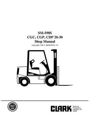
  • 1. Copyrighted Material Intended for CLARK dealers only Do not sell or distribute SM498S CGC, CGP, CDP 20-30 Shop Manual VOLUME 1 OF 2, GROUPS 00 - 03
  • 2. Copyrighted Material Intended for CLARK dealers only Do not sell or distribute Truck Models Covered by this Manual This manual consists of a “base” module that pertains to ail Genesis models and other modules that pertain only to You may, however, purchase specific modules and expand specific models. Manuals shipped with the truck contain your manual to fully cover multiple models. To do so, the base module and the modules specific to the purchased order the desired modules as you would any other Clark part. truck. Arrangement and Use of this Manual Clark armuges parts and service procedures by standard- ized Groups. In this manual, Groups are similar to “chap- ters.” Groups are listed in the indexes on the next page. Each Group begins with a table of contents that shows the You can quickly locate a specific point in the manual by using the headers and footers that appear on every Section page. The following illustration points out these areas. Sections contained within the Group. Lengthy Sections also begin with a table of contents. Each Group and Section has an identifying name and number, or “ID.” Each page also has a unique ID The page ID consists of three numbers separated by hyphens. The three numbers represent the Group number, the Section number, and the page number. For example, “00-1-2” on the lower comer ns In Section ID / Mania,ID Section ID of the page indicates Group 00, Section 1,Page 2. The Group number sometimes has a letter or letters added to it in parentheses if one or more variations of the Group This manual is intended for the use of trained service exist. For example, if the truck has a standard transaxle, personnel. Please read Group SA, “Safe Maintenance,” Group 06 is expressed as “06(S);” if the truck has a hydro- and the Operator’s Manual before working on or operat- static transmission, Group 06 is expressed as “06(H).” ing the truck. 0 Copyright Clark Material Handling 1994 SM 598,Oct ‘94
  • 3. Copyrighted Material Intended for CLARK dealers only Do not sell or distribute CONTENTS Group SA. SafeMaintenance Group PS. Periodic Service Group 00. Engines Group 01. Cooling System Groupo2.Fuel System Group 03. Air Induction System Group 06. Transmission Group 12. Ignition System Group w. Instrument Pod Group 14. Electrical System Contents of this Manual Group Index Group 34. Uprights Y Group 22. Group 23. Group 25. Group 26. Group 29. Group 30. Group 32. Group 34. Group 38. Group 40. Alphabetical Index (SEE NEXT PAGE) Pictorial Index Wheels and Tires Brake System Steering Column and Gear Steer Axle Hydraulic Pump, Sump, and Filters Hydraulic Control Valve/Lii Circuit Tilt Cylinders uprights Counterweight, Sheet Metal, & Chassis Specifications Group 32. Tilt Cylinders n n /Group 06. Transmission II / Group 23. Brake/Inching System SM 598, Apr ‘96 Contents-l
  • 4. Copyrighted Material Intended for CLARK dealers only Do not sell or distribute GROUP SA GROUP SA SAFE MAINTENANCE Safety ............................................................................... Section 1 Lifting, Jacking, and Blocking the Truck ..................... Section 2 Towing .............................................................................. Section 2 SM 598, OCT ‘94 Safe Maintenance
  • 5. Copyrighted Material Intended for CLARK dealers only Do not sell or distribute CMRK Group SA, Safe Maintenance Section 1. Safety SafetySigns and Messages Safe Maintenance Practices Safety signs and messages in this manual and on the lii truck provide instructions and identify specific areas where potential hazards exist and special precautions should be taken. Be sure you know and understand the meaning of these instructions, signs, and messages. Damage to the truck, death, or serious injury to you or other persons may result if these messages are not followed. NOTE This message is used when special informa- tion, instructions or identification is re- quired relating to procedures, equipment, tools, pressures, capacities, and other spe- cial data. The following instructions have been prepared from cur- rent industry and government safety standards applicable to industrial truck operation and maintenance. These rec- ommended procedures specify conditions, methods, and accepted practices that aid in the safe maintenance of in- dustrial trucks. They are listed here for the reference and safety of all workers during maintenance operations. Care- fully read and understand these instructions and the spe- cific maintenance procedures before attempting to do any repair work. When in doubt of any maintenance procedure, please con- tact your local Clark dealer. 1. IMPORTANT Powered industrial trucks can become hazardous if maintenance is neglected. Therefore, suitable mainte- nance facilities, trained personnel, and procedures must be provided This message is used when special precau- tions should be taken to ensure a correct action or to avoid damage to, or malfunc- tion of, the truck or a component. 2. Maintenance and inspection of all powered industrial trucks shall be done in conformance with the manufacturer’s recommendations. 3. A CAUTION This message is used as a reminder of safety hazards that can result in personal injury if proper precautions are not taken. 4. A scheduled planned maintenance, lubrication, and inspection program shah be followed. Only trained and authorized personnel shah be permit- ted to maintain, repair, adjust, and inspect industrial trucks. Work should be performed in accordance with the manufacturer’s specifications. A WARNING This message is used when a hazard exists that can result in injury or death if proper precautions are not taken. 5. 6. A DANGER This message is used when an extreme haz- ard exists that can result in injury or death or serious injury if proper precautions are not taken. Properly ventilate work area vent exhaust fumes, and keep shop clean and floor dry. Avoid fire hazards and have fire protection equipment present in the work area Do not use an open flame to check for level or leakage of fuel, electrolyte, or coolant. Do not use open pans of fuel or flammable cleaning fluids for cleaning parts. 7. The above terms have been adopted by Clark Material Handling Company. The same terms may be used in differ- ent context in service literature supplied directly or indi- rectly by vendors of truck components. Before starting work on truck: a. Raise drive wheels off of floor or disconnect power source and use blocks or other positive truck positioning devices. b. Disconnect battery before working on the electri- cal system. 8. Before working on engine fuel system of gasoline- or diesel-powered trucks, be sure the fuel shut-off valve is closed. SM 598,Oct ‘94 Safety l SA-l-1
  • 6. Copyrighted Material Intended for CLARK dealers only Do not sell or distribute Group SA, Safe Maintenance EUIRK 9. 10. 11. 12. 13. 14. 15. 16. 17. 18. Operation of the truck to check performance must be conducted in an authorized, safe, clear area. Before starting to drive truck: a. Be in operating position. b. Be sure parking brake is engaged. c. Put direction control in neutral. d. Start engine. e. Check functioning of direction and speed con- trols, steering, brakes, warning devices, and any load handling attachments. 19. 20. 21. Modifications and additions that affect capacity and safe truck operation must not be done without the manufacturer’s prior written approval. Capacity, op- eration and maintenance instruction plates, tags, or decals must be changed accordingly. This is an OSHA requirement. Care must be taken to assure that all replacement parts, including tires, are interchangeable with the original parts and of a quality at least equal to that provided in the original equipment. Parts, including tires, are to be installed per the manufacturer’s procedures. Always use genuine CLARK or CLARK-approved parts. Before leaving truck a. Stop truck. b. Put directional control in neutral. c. Apply the parking brake. d. Stop the engine by turning off the ignition circuit. e. Put blocks at the wheels if truck is on an incline. Brakes, steering mechanisms, control mechanisms, warning devices, lights, governors, guards, safety de- vices, and frame members must be carefully and regu- larly inspected and maintained in a safe operating condition. Use special care when removing heavy components from the truck, such as counterweight, seat deck, upright, etc. Be sure that lifting and handling equip- ment is of the correct capacity and in good condition. Also, this removal may upset the stability of the truck. The frame must always be safely blocked for major component removal. NOTE Special trucks or devices designed and approved for hazardous area operation must receive special atten- tion to ensure that maintenance preserves the original, approved, safe-operating features. You should also be familiar with additional operating and maintenance safety instruc- tions contained in the following publica- tions: Fuel systems must be checked for leaks and condition of parts. Extra special consideration must be given in the case of a leak in the fuel system. Action must be taken to prevent the use of the truck until the leak has been corrected. ANSVASMEB56.1- 1988Operator Control-Industrial Tow Tractors (Safety Standard For Powered Industrial Trucks). Published by: Society of Mechanical Engineers, United Engineering Center, 345 E. 47th Street, New York, NY 10017. The truck manufacturer’s capacity, operation, and maintenance instruction plates, tags, or decals must be maintained in legible condition. NFPA 505-1982: Fire Safety Standard for Powered Indus- trial Trucks: Type Designations, Areas of Use, Mainte- nance and Operation. Available from: National Fire Protection Assoc., Inc., Batterymarch Park, Quincy, MA 02269. Batteries, motors, controllers, limit switches, protec- General Industrial Standards, OSHA 2206: OSHA Safety tive devices, electrical conductors, and connections and Health Standards (29 CFR 1910), Subpart N-Materials must be inspected and maintained in conformance Handling and Storage, Section 1910.178 Powered Indus- with good practice. Special attention must be paid to trial Trucks. For sale by: Superintendent of Documents, the condition of electrical insulation. U.S. Government Printing Office, Washington, DC 20402. To avoid injury to personnel or damage to the equip- ment, consult the manufacturer’s procedures inreplac- ing contacts on any battery connection. Industrial trucks must be kept in a clean condition to minimize fire hazards and helpin the detection of loose or defective parts. SA-1-2 l Safety SM 598,Oct ‘94
  • 7. Copyrighted Material Intended for CLARK dealers only Do not sell or distribute CMRK Group SA, Safe Maintenance Lifting, Jacking, and Blocking 3 Safe Parking ....................................................................................................................................& Lifting, Jacking, and Blocking Points ..........................................................................................2 Raising Drive Wheels Off Floor ....................................................................................................2 Raising Truck with A Hoist ..........................................................................................................3 Blocking the Upright in Raised Position ......................................................................................4 Raising Rear of Truck ...................................................................................................................4 Section 2. Raising Entire Truck .....................................................................................................................5 Shipping Tie-Down Instructions ...................................................................................................6 A WARNING Lifting or jacking any large piece of equipment such as your fork truck presents obvious hazards. It must be done with great care and forethought. Consult the truck weight tabulations in Group 40, “Specifications” to ensure that your lifting equipment is of adequate capacity. SM 598,Oct ‘94 Lifting, Jacking, and Blocking l SA-2-1
  • 8. Copyrighted Material Intended for CLARK dealers only Do not sell or distribute Group SA, Safe Maintenance CUlRK Safe Parking Before working on truck: 1. Park truck on a hard, level, and solid surface, such as a concrete floor with no gaps or breaks. 2. Put upright in vertical position and fully lower the forks or attachment. 3. Put all controls in neutral. Turn key switch OFF and remove key. 4. Apply the parking brake and block the wheels. A WARNING Defective equipment can cause accidents. All tools and lifting equipment must be in good condition, meet the load capacity re- quirements and have OSHA labels when required. Tools with defects can have fail- ures causing severe injury or death. Lifting,Blocking,andJackingPoints Use the following illustration to locate general lifting, block- ing, and jacking points on the truck. Read the procedures for raising, blocking, or jacking specific components of the truck to make sure you understand the correct, safe proce- dures. ‘hnder Steer L Under Frame L Under Upright Axle Frame Mount A WARNING Do not attempt to lift the truck by the over- head guard or the counterweight. Severe injury may result and the truck can be damaged. RaisingDriveWheelsOff Floor This procedure uses the upright as a lever to lift the drive wheels off the floor and prevent accidents due to inadvert- ent powering of the drive wheels. Park truck safely as described in “Safe Parking.” Block steer wheels. Be sure upright trunnion bolts are tight. Bolt torques must be 75-80 Nom (55-59 ft-lb). Start the engine. Tilt the upright fully back. Adjust upright height as necessary to put blocking underneath the lower end of the upright. Put a solid 100 x 100 mm (4 x 4 in) hardwood block under the front section of each upright rail. Put a 3-6 mm (.125-.250 in) steel plate on top of each block. 5. Tilt upright fully forward. This raises the drive wheels off the floor. Release the tilt control lever and turn engine OFF. SA-2-2 . Lifting, Jacking, and Blocking SM 598,Oct ‘94
  • 9. Copyrighted Material Intended for CLARK dealers only Do not sell or distribute ClRRK Group SA, Safe Maintenance 6. Insert blocking under the frame behind the drive wheels or slip wheel cradles under the drive wheels. If using blocking, check for safe clearance between drive wheels and floor and blocks. 7. 8. NOTE When forks are raised as in illustration above, use shop rags, paper, or bright tape on fork tips to signal the danger of trip- ping. Check for stable condition of the truck. Be sure that the blocks are located securely under the truck frame before operating the drive or working on truck. Lower the drive wheels to the floor and remove the blocks by reversing the above procedure. RaisingTruck with A Hoist When suitable equipment is available, the front of the truck may be raised by means of a hoist, with wheel cradles placed under the wheels or blocking placed under the frame. n ! CAUTION When lifting the front of the truck watch truck for signs of lateral instability. It may tip sideways. You may have to support or guide the side of the truck or overhead guard to prevent tipping. 1. Park truck safely as described in “Safe Parking.” Block rear steer wheels. 2. Check trunnion bolts to make sure they are tightened to correct torque. Bolt torques must be 75-80N.m (55-59 ft-lb). 3. To raise the front of the truck using the upright, spread two chains on the outer rail tiebar of the upright. 4. A WARNING Chain and hoist used to lift truck should be checked to make sure they are of safe Iift- ing capacity. See the truck data plate for information. Slowly lift truck and lower drive wheels onto the cradles or place blocking under frame prop points. 5. When maintenance work is completed, lower the truck to the floor by reversing the lifting procedure. Check to be sure no tools or equipment are under the truck or wheels. SM 598,Oct ‘94 Lifting, Jacking, and Blocking l SA-2-3
  • 10. Copyrighted Material Intended for CLARK dealers only Do not sell or distribute Group SA, Safe Maintenance ClmK Blocking the Upright In Raised Position This procedure is used to safely provide clearance for access from the front of truck to components on or near the drive axle. Illustrations show upright with forks removed however, fork removal is not necessary 1. 2. 3. 4. 5. 6. Park truck safely as described in “Safe Parking.” Put blocks in front of and behind drive wheels. Put wooden support blocks conveniently near upright rails before raising the upright. Use two 100 x 100 mm (4 x 4 in) hardwood blocks or equal, of about 300 x 300 mm (12 in) and 600 x 600 mm (24 in) length. NOTE For standard uprights, block may need length cut to suit. For triple stage uprights, the carriage may be blocked up, as shown. Start engine and raise the upright carriage. Hold the taller block against inner rail and lower the upright until carriage rests on block. Outer Rail Hold the shorter block against the outer rail and lower the upright until inner rail rests on the block. Outer Rail II II ”Al/II/le Carriage .*II I Short Block 7. Reverse the procedure to remove blocking. RaisingRear of Truck The truck may be raised at the rear by jacking and blocking under the center of the frame member at either the front or rear steer axle mounting, or under the center section of the steer axle. Refer to truck data plate for truck weights. 1. A WARNING An incorrectly installed counterweight can move or fall unexpectedly. Never lift or block a truck using the counterweight. Fail- ure to follow procedures outlined in this manual can result in injury or death. Park truck safely as described in “Safe Parking.” Put blocks at front and rear of drive wheels. SA-2-4 l Lifting, Jacking, and Blocking SM 598,Oct ‘94
  • 11. Copyrighted Material Intended for CLARK dealers only Do not sell or distribute ClRRK Group SA, Safe Maintenance 2. Put a floor jack under the steer axle mounting frame member, centered between the two wheels. A WARNING Never lift the truck by the counterweight. 3. 4. NOTE If there is insufftcient clearance under frame for your jack, the truck may fmt be driven onto shims, such as 25 x 150 x 300 mm (1 x 6 x 12 in) pieces of board, to increase the truck frame underclearance. Raisethetruckonlyashighasnecessary toperformthe maintenance work Put blocks at both sides of the truck, fully under the frame main side structure. Put theblocks in front of but close to the counterweight and steer wheels for best truck stability. Put equal blocks under each sideofthetruck to provide a level working position. 5. Lower the truck onto the blocks and remove the jack. n ! CAUTION Before performing any maintenance, check the truck for stabilitY on the blocks. 6. When maintenance work is completed, lower the rear of truck to the floor by reversing the above procedure and lowering each side of the truck 50 mm (2 in) at a time: l Put jack under frame and raise truck l Carefully remove blocks and lower truck. l Remove jack and blocks from drive wheels. RaisingEntireTruck Refer to truck data plate for truck weights. 1. 2. Park truck safely as described in “Safe Parking.” Lower upright fully. If necessary, drive truck onto boards to increase undercLearance. A WARNING SIDE-TO-SIDE TIPOVER. When jacking side of truck, be sure upright is lowered fully and do not raise one side of the truck more than about 50 mm (2 in) higher than the other, to avoid tipping truck over later- ails* END-TO-END TIPOVER. If the upright and &ansaxle are removed while the truck is blocked up, the truck will tip backwards due to the heavy counterweight. Both up- right and counterweight must be removed before attempting to raise the truck for transaxle removal. The back of the truck must be supported by blocking under the steer axle to prevent movement. The reverse is also true. If the counter- weight is removed while the truck is up on blocks, the weight of the upright and transaxle will cause the truck to tip on the front blocks and fall forward. SM 598,Apr ‘96 Lifting,Jacking,and Blocking l SA-2-5
  • 12. Copyrighted Material Intended for CLARK dealers only Do not sell or distribute Group SA, Safe Maintenance emu 3. Put the jack under side frame near the center of the truck. 4. 5. IMPORTANT Be sure to put the jack squarely and fully under the main side structure of the frame. Do not put the jack under the outer covers which enclose the fuel and hydraulic sump tanks. Carefully raise the truck one sideat a time, only as high as necessary to do the maintenance work and not more than a maximum of 150 mm (6 in) total. Putblocks under the sideframe, at each side ofthejack. Spread the blocks close to the steer and drive wheels for maximum stability. 6. 7. If using one jack, lower the truck onto the blocks and move the jack to the opposite side. Repeat the lifting procedure. Put the same size blocks under each side of the truck so it will be level. 0! CAUTION Before performing any maintenance work, check the truck for stable condition on the blocking. When maintenance work is completed, lower the en- tire truck to the floor by reversing thelifting procedure. Lower the truck one side at a time, while carefully removing the blocks. Check to be sure no tools or equipment are under the truck or wheels. NOTE Depending on jack height, shims under the tires may be needed for clearance to allow removal of jack. Shipping Tie-Down Instructions Front of Truck a. With Upright and Carriage Installed l Lower the carriage fully. l Put a tie down (e.g., chain) between the carriage fork bars. b. Without an Upright and Carriage Installed l Put a chain across the truck floor plate. Protect truck from chain damage by using covered chain or protective material under the chain at contact points. Rear of Truck l Attach the tie down to pocket in bottom of coun- terweight. SA-2-6 l Lifting, Jacking, and Blocking SM 598,Oct ‘94
  • 13. Copyrighted Material Intended for CLARK dealers only Do not sell or distribute Group 25, Steering Column and Gear CIARK Disassembly Cleanliness is extremely important when repairing a steer- ing gear. Work in a clean area. Before disconnecting lines, clean port area of unit thoroughly. Use a wire brush to remove foreign material and debris from around exterior joints of the unit. NOTE Although not all illustrations show the unit in a vise, it is recommended to keep the unit in the vise during disassembly. Follow the clamping procedures explained throughout the text. Meter (Gerotor) End 1. Clamp unit in vise, meter end up. Clamp lightly on edges of mounting area, as shown. Use protective material on vise jaws. Do not over-tighten jaws. Remove meter (gerotor). Be careful not to drop star (rotor). Rotor Remove seal from meter. Remove drive spacer(s). Remove drive. ,e Capscrew . 1 2. Remove capscrews. Control End Sial Cap Screw 3. Remove end cap. 4. Remove seal from end cap. cer are 9. Remove spacer plate. 10. Remove seal from housing. 11. Remove housing from vise and place on a clean soft cloth to protect surface finish. Use athin-bladed screw- driver to pry retaining ring from housing. 25-5-2 l Steering Gear Overhaul SM 598,Oct ‘94
  • 14. Copyrighted Material Intended for CLARK dealers only Do not sell or distribute emK Group 25, Steering Column and Gear 12. Place assembly so shaft is horizontal. Rotate spool and sleeve until pin is horizontal. Push spool and sleeve assembly forward with your thumbs just far enough to free seal gland bushing from housing. Remove bush- ing. Seal Gland Bushing 13. Remove quad ring seal from seal gland bushing. Dust Seal / _. - 14. Use a thin-bladed screwdriver to pry dust seal from seal gland bushing. Do not damage bushing. 15. Remove two bearing races and the needle thrust bear- ing from spool and sleeve assembly. Needle Bearing Thrust Bearing Race Bearing/w 16. Remove spool and sleeve assembly from cap (14-hole) end of housing. Pin 17. 18. Push pin from spool and sleeve assembly. Push spool partially from control end of sleeve, then remove six centering springs from spool carefully by hand. Note their position in the unit before they are removed. 19. Push spool back through and out of sleeve. Rotate spool slowly when removing from sleeve. 20. Remove seal from housing. (Not used on ’ C;“;k t ‘Check units with Check Ball integral column) Seat 7/16” Seal Ball Retainer 21. 22. Remove set screw from housing. Screw a l/8-inch-24 NC machine screw into end of check ball seat. Then pull on screw with pliers to lift seat out of housing. 23. Remove two seals from check valve seat. 24. Tip housing to remove check ball and check ball retainer. IMPORTANT Do not bind spool and sleeve in housing. Rotate spool and sleeve assembly slowly when removing from housing. SM 598,Oct ‘94 Steering Gear Overhaul l 25-5-3
  • 15. Copyrighted Material Intended for CLARK dealers only Do not sell or distribute Group 25, Steering Column and Gear ElRRK Parts Inspection Inspect all parts for damage, cracks, broken parts, damaged threads, corrosion or erosion of surfaces, worn spots, nicks or scratches. Check all mating surfaces. Replace any parts that have scratches or burrs that could cause leakage. Discard all old seals and replace with new ones. Clean all metal parts in clean solvent. Blow dry with air. Do not wipe dry with cloth or paper towel because lint or other matter can get into the hydraulic system and cause damage. Do not use a coarse grit or try to file or grind these parts. If parts are left exposed, cover them with a clean cover to prevent airborne dust from collecting on them. Reassembly Refer to Service Parts Book when ordering replacement parts. A good service policy is to replace all old seals with new seals at overhaul. NOTE Lubricate all seals (with exception of new quad ring seal) with clean petroleum jelly such as Vaseline. Do not use excessive lubricant on seals for meter (gerotor) section. Make sure all parts are clean and free of dust. Before assembly, lightly coat all in- ternal metal parts with oil. Control End 1. Use a needle-nosed pliers to lower check ball retainer into check valve hole of housing. Make sure retainer is straight (not tilted on edge) in housing. e-- Set Screw ( Not Used on Units with Integral Column - See Figure 12A 1 Check Ball Seat .Seal 0 ” Seal 0 3.9 &!z 0 4 e 4m Check Ball Check Ball Retainer (Standard Steering Figure 12 Control Unit) 2. Install check ball in housing. 3. Lubricate 5/8-inch diameter seal and 7/16-inch diam- eter seal. Install seals on check ball seat, as above. 4. 5. 6. 7. Lubricate check ball seat and seals thoroughly before installing seat in housing. When installing seat do not twist or damage seals. Install check ball seat in hous- ing; insert open end of seat first. Push check ball seat to bottom of hole. Install set screw. Use a 5/16-inch Allen wrench to torque set screw to 11 Nom (100 in-lb; 8.3 ft-lb). To prevent interference of parts, make sure top of set screw is slightly below housing mounting surface. Assemble spool and sleeve carefully so that the spring slots line up at the same end. Rotate spool while sliding parts together. Some spool and sleeve sets have iden- tification marks; align these marks. Test for free rota- tion. Spool should rotate smoothly in sleeve with finger tip force applied at splined end. Bring spring slots of both parts in line and stand parts on end of bench. Insert spring installation tool (avail- able as Part No. 6000057) through spring slots of both parts. Position three pairs of centering springs (or two sets of 3 each) on bench so that extended edge is down and arched center section is together. In this position, insert one end of entire spring set into spring installa- tion tool, as shown. On those units which use the low torque centering springs, there are two pairs of centering springs (or two sets of each) and one pair (two) spring spacers. The spring spacers are installed together between the two sets of centering springs. The installation procedure is the same as that used on the standard (three pairs of centering springs) units. 25-S-4 l Steering Gear Overhaul SM 598,Oct ‘94
  • 16. Copyrighted Material Intended for CLARK dealers only Do not sell or distribute CWRK Group 25, Steering Column and Gear 8. 9. 10. 11. 12. Compress extended end of centering spring set and push into spool sleeve assembly withdrawing installa- tion tool at the same time. Center the spring set in the parts so that they push down evenly and flush with the upper surface of the spool and sleeve. Install pin through spool and sleeve assembly until pin becomes flush at both sides of sleeve. Pin Position the spool and sleeve assembly so that the splined end of the spool enters the 1Chole end of housing first. IMPORTANT Be extremely careful that the parts do not tilt out of position while being installed. Push parts gently into place with slight ro- tating action; keep pin nearly horizontal. Push the spool assembly entirely within the housing bore until the parts are flush at the meter end or 16hole end of housing. Do not push the spool assembly beyond this point to prevent the cross pin from drop- ping into the discharge groove of the hous- ing. With the spool assembly in this flush position, check for free rotation within the housing by turning with light finger tip force at the splined end. Place housing on clean, lint free cloth. Install 2-1/8- inch diameter seal in housing. 13. Install two bearing races and the needle thrust bearing in the order shown. Needle 14. 15. Install I-l/4-inch diameter dust seal in seal gland bushing; flat or smooth side of dust seal must face down towards bushing. Install dry quad ring seal in seal gland bushing. Smooth seal in place with your finger. Do not use any seal that falls freely into pocket of bushing. Seal should not “fall” into place but should require light force to seat. Seal Gland - Bushing (with seals) Retaining Ring SM 598,Oct ‘94 Steering Gear Overhaul l 25-5-5
  • 17. Copyrighted Material Intended for CLARK dealers only Do not sell or distribute Group 25, Steering Column and Gear CUIRK 16. Install seal gland bushing over the spool end with a twisting motion. Tap the bushing in place with arubber hammer. Make sure the bushing is flush against the bearing race. On those units which use the Teflon seal, install the Teflon back-up ring into the recess cut into the seal gland bushing. Install the Teflon seal over the spool end, then carefully install the seal gland bushing over the spool end using a rotary motion. NOTE The seal gland bushing which is used with the Teflon seal is not the same as the seal gland bushing used with the standard quad- ring seal. The seal gland bushing with the Teflon seal has an identification groove cut into the outer diameter of the bushing. The grooved bushings can only be used with the Teflon seals and the non-grooved bushings used only with the quad-ring seals. Teflon Seat 17. Install retaining ring in housing. After installing ring, tap on ring or pry with screwdriver around entire circumference of ring to properly seat ring in groove. Meter (Gerotor) End 18. Clamp housing in vise, as shown. Clamp lightly on edges of mounting area. Do not overtighten jaws. NOTICE Check to ensure that the spool and sleeve are flush or slightly below the surface of the housing. IMPORTANT Clean the upper surface of the housing by wiping with the palm of clean hand. Clean each of the flat surfaces of the meter sec- tion parts in a similar way when ready for reassembly. Do not use cloth or paper to clean surfaces. 19. Install 3-inch diameter seal in housing. - Seal 20. 21. Install spacer plate. Align bolt holes in spacer plate with tapped holes in housing. Rotate spool and sleeve assembly until pin is parallel with port face. Install drive, making sure you engage drive with pin. Spacer Plate 25-5-6 l Steering Gear Overhaul SM 596,Oct ‘94
  • 18. Copyrighted Material Intended for CLARK dealers only Do not sell or distribute ClClRU Group 25, Steering Column and Gear 24. Install drive spacer(s) when used, in meter. 22. Install 3-inch diameter seal in meter (gerotor). 23. With seal side of meter toward spacer plate, align star valleys on drive. Note the parallel relationship of reference lines A, B, C, and D in figure. Align bolt holes without disengaging meter from drive. Be sure star has engaged drive spline in position shown. IMPORTANT Failure to properly install drive and pin may cause unit to self steer. NOTE To assure proper alignment, mark spline end of drive shaft with a line parallel to slot on other end, before installing. Meter (Gerotorl Star VakV Pin Port Face cu. m/rev. Displ. Unit equires 2 Spacers 25. 26. 27. 28. Install 3-inch diameter seal in end cap. Install end cap on gerotor, and align holes. Install 7 &y cap screws in end cap. Pretighten.screws to initial torque of 17 I+m (150 in-lb), then torque screws to final torque of 31 N*m (275 in-ib) in the sequence shown. Inspect the assembly to be sure all parts have been installed and fasteners correctly installed and tight- ened. (Reprint courtesy of EATON Corporation) SM 598,Oct ‘94 Steering Gear Overhaul l 25-5-7
  • 19. Copyrighted Material Intended for CLARK dealers only Do not sell or distribute GROUP 26 GROUP 26 STEER AXLE Steer Axle Specifications and Description .................... Section 1 Steer Axle Wheel Bearing Maintenance and Adjustment.. ........ ................................................................................... Section 2 Steer Axle Removal and Replacement .......................... Section 3 Steer Axle Overhaul ........................................................ Section 4 Steer Cylinder Removal and Replacement ................... Section 5 Steer Cylinder Overhaul ................................................ Section 6 SM 598,Oct ‘94 Steer Axle
  • 20. Thank you very much for your reading. Please Click Here. Then Get COMPLETE MANUAL. NO WAITING NOTE: If there is no response to click on the link above, please download the PDF document first and then click on it.
  • 21. Copyrighted Material Intended for CLARK dealers only Do not sell or distribute clmu Group 26, Steer Axle Steer Axle Specifications Cushion-Tire Steering System Relief Pressure Setting: (1200-1300 psi). Section 1. Specifications and Description 8270-8960 kPa Steer Cylinder Type: Double-acting, piston-type. Turning Arc: 83” maximum inside turning angle; 60” maxi- mum outside turning angle. Pneumatic-Tire Steering System Relief Pressure Setting: 8970 kPa (1300 psi) Steer Cylinder Type: Double-acting, piston-type Turning Arc: 75”maximum inside turning angle; 54” maxi- mum outside turning angle. Bearing Grease: Grade No. 2 EP multi-purpose grease, Clark Part MS-107C. Fastener Torques Steer Axle Mounting Bolts: 170-190 Wm (125-140 ft-lb) Cylinder to Axle Mounting Bolts: 280-320 Wm (205-234.5 ft-lb) Steering Link to Steering Knuckle Nuts: 135-150 Nom (9% 110 ft-lb) Steer Knuckle King Pin Castle Nuts: See installation proce- dures in Section 4, “Steer Axle Overhaul.” Service intervals Steering Linkage Inspection and Lubrication: Every 50- 250 hours and each PM. Steer Wheel Bearing Inspection and Lubrication: Every 500 hours of operation. Steer Cylinder Seals Leakage Check: Every 50-250 hours and each PM. Steer Axle Mounting Inspection: Every 50-250 hours and each PM. Power Steering Relief Pressure Check: Every year or 2000 hours of operation. Description The steer axle has the steer cylinder, steer knuckles, and steering links mounted on it. All these components can be removed, serviced, and replaced. The steering gear (steering control unit) at the base of the steering column directs hydraulic fluid to one end or the other of the steer cylinder to pivot the steer wheels. The steer axle is bolted to the truck frame. The steer cylin- der is connected to the steering knuckles by steer links. Mounting trunnions allow the axle to tilt independently of the truck and “silent” mounts cushion the axle on the trunnions. All bearings used in the steer axle linkage have lubrication fittings and are serviceable. Axle removal, replacement, and service for all components, including overhaul of the steer cylinder, is explained in the Sections for this Group. SM 598, Ott ‘94 Steer Axle Specifications and Description l 26-l-l
  • 22. Copyrighted Material Intended for CLARK dealers only Do not sell or distribute Group 26, Steer Axle CIRRK Steer - Cylinder Axle Mounting frunnion Silent Mount Steer Axle 7 Steer Steer Knuckle ‘-ink Steer Axle and Mounting - Cushion-Tire Axle Steer - Cylinder Mounting Trunnion Steer Knuckle Steering J Link Steer Axle and Mounting - Pneumatic-Tire Axle 26-1-2 l Steer Axle Specifications and Description SM 598,Oct ‘94
  • 23. Copyrighted Material Intended for CLARK dealers only Do not sell or distribute CHIC Group 26, Steer Axle Section 2. Steer Axle Wheel Bearing Maintenance and Adjustment Wheel Bearing Check ...................f................................................................................................ 1 Wheel Bearing Lubrication ...........................................................................................................1 Bearing Disassembly ....................................................................................................................... 2 Bearing Reassembly ......................................................................................................................... 3 Wheel Bearing Adjustment ...........................................................................................................4 IMPORTANT Before removing any component for overhaul, make sure the correct repair parts, seals, and gasket sets are available. A CAUTION SAFE PARKING. Before working on truck: Park truck on a hard, level, and solid surface, such as a concrete floor with no gaps or breaks. Put upright in vertical position and fuBy lower the forks or attachment. Put ah controls in neutral. Turn key switch OFF and remove key. Apply the parking brake and block the wheels. Wheel Bearing Check A wheel bearing check should be performed about every 500 hours of operation or three or four times a year. Wheel bearings need adjustment only after 2000 hours or as needed. It is recommended that you clean and repack the bearings before adjustment. Check hourmeter total hours and refer to the truck’s PM schedule. See steer wheel bearing lubrication procedure below. To check the steer wheel bearings for excessive free play or looseness: 1. Grasp the wheel with both hands and try to move it by a rocking motion top-to-bottom. 2. Try to pull it in and out along the wheel spindle. Watch for excessive free movement in wheel bearings or steering knuckle bearings. There should be a small amount of free movement. If the wheel has excessive free move- ment, the bearings require additional service and/or adjust- ment. Wheel Bearing Lubrication These procedures cover bearing lubrication for the two types of steer wheels used on the truck; pneumatic-tire wheels which are mounted on a hub that contains the bear- ing components and cushion-tire wheels with the bearings installed in the wheel. Use the procedures to clean, repack and adjust bearings for both the cushion-wheel and the pneumatic-tire hub. Pneumatic-Tire Wheel Mounting ,CushiFr , Steer Axle Knuckle 1 I I Pneumatic-tire (lef) and cushion-tire (right) wheel- bearing assemblies. The bearing components and arrangement are the same for both the cushion and pneumatic types. Instructions for repacking/lubricating the bearing components apply to both types* SM 588,Oct ‘84 Steer Axle Wheel Bearing Maintenance and Adjustment l 26-2-l