Preparing for Transportation Electrification: The Electric Coop Perspective
Clark wp45 forklift service repair manual
1. 2317 Alumni Park Plaza
Suite 500
Lexington, KY, 40517
USA
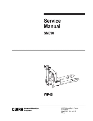
Service
Manual
SM698
WP45
2. Standard Codes
F-code Section C-code
Version no T-code
000 390
1
SM-698
Standard Codes
B-Code = Business area
F-Code = Product family
T-Code = Product type
C-Code = Component function
Worksheet standard
W-Code = Working code
R-Code = Reason code
SO-Code = Assortment
F-Code List
PT Powered Pallet Trucks
T-Code List
No. Model
390 WP45
C-Code List
No Function Group C-Code
0 Chassis 0000
1 Motors 1000
2 Drive Gear / Transmission 2000
3 Brake / Wheel System 3000
4 Steering System 4000
5 Electrical System 5000
6 Hydraulic / Pneumatic System 6000
7 Operating Function-lifting Cylinder 7000
8 Peripheral / Installation Equipment 8000
3. 000 390
Version no T-code
F-code Section C-code
Standard Codes
2
9 Optionals / Attachments 9000
10 Tools 10000
SM-698
4. Table of Contents
3
Standard Codes ............................................................................................. 1
Warning Symbols ......................................................................................... 11
Warning Levels ......................................................................................... 11
Prohibitory Symbols .................................................................................... 12
Ordinance Symbols .................................................................................. 12
Safety ............................................................................................................ 13
General Safety .......................................................................................... 13
Battery Safety ............................................................................................... 17
Static Safety .................................................................................................. 22
Welding Safety ............................................................................................. 23
Introduction, Service Manual ...................................................................... 25
Contents, Section M ..................................................................................... 27
Machine Information ................................................................................. 27
General Product Information ...................................................................... 29
Truck Presentation. ................................................................................... 29
Truck Side Views ................................................................................... 29
Intended Truck Application .................................................................... 30
Prohibited Truck Application .................................................................. 30
Truck Data ............................................................................................. 30
Truck Dimensions .................................................................................. 31
Data Plate .............................................................................................. 32
Main Components ..................................................................................... 33
Inch and Metric (SAE) Fasteners ............................................................... 35
Introduction ............................................................................................... 35
Nomenclature, Threads ............................................................................ 36
Strength Identification ............................................................................... 37
Conversion of English and Metric Units .................................................... 44
Technical Service Data ................................................................................ 47
Ordering Spare Parts ................................................................................... 49
Contents, Section P ..................................................................................... 51
Planned Maintenance ............................................................................... 51
Introduction, Maintenance .......................................................................... 53
SM-698
5. Table of Contents
4
Jacking Truck Off The Floor ..................................................................... 54
Elevate Rear of Truck ............................................................................ 54
Elevate Either Side of Truck .................................................................. 54
Lubricants ................................................................................................. 55
Standard ................................................................................................ 55
Corrosion ............................................................................................... 55
Cold Storage .......................................................................................... 56
Service Schedule ......................................................................................... 59
Planned Maintenance Schedule ............................................................... 59
Planned Maintenance Procedures ............................................................ 63
Services Performed Daily or Every 8 Operating Hours .......................... 63
Battery Discharge Indicator with lift interrupt (optional) .............. 63
Hydraulic System ....................................................................... 63
Frame/Sheet Metal ..................................................................... 64
Wheels/Tires .............................................................................. 64
Functions/Operations ................................................................. 64
Services Performed Monthly or Every 120 Operating Hours ................. 65
Inspection ................................................................................... 65
Transmission .............................................................................. 65
Brakes ........................................................................................ 65
Battery ........................................................................................ 65
Electrical Connections ................................................................ 66
Main Contactor ........................................................................... 66
Motor Brushes ............................................................................ 66
Drive Motor ................................................................................. 66
Hydraulic Reservoir .................................................................... 66
Frame Lube ................................................................................ 67
Pivot Points ................................................................................ 67
Services Performed Every 480 or 960 Operating Hours ........................ 68
Drive Motor ................................................................................. 68
Services Performed Annually or Every 1440 Operating Hours .............. 69
Inspection ................................................................................... 69
Transmission .............................................................................. 69
Battery ........................................................................................ 69
Hydraulic System ....................................................................... 70
Brakes ........................................................................................ 70
Lubrication Chart ......................................................................................... 71
Oil and Grease Specifications .................................................................... 72
Approved Oils and Grease ....................................................................... 72
Grease Location Points ............................................................................ 72
Contents, Section S ..................................................................................... 73
Service Instructions .................................................................................. 73
SM-698
6. Table of Contents
5
Chassis/Lift Frame ....................................................................................... 75
Pull rod ...................................................................................................... 76
Removal ................................................................................................. 76
Inspection ............................................................................................... 77
Installation .............................................................................................. 78
Carrier Frame Bushings ............................................................................ 80
Inspection Covers ........................................................................................ 81
General Information .................................................................................. 81
Driver Controls ............................................................................................. 85
Decals ............................................................................................................ 87
Decal with Protective Sheet ...................................................................... 87
Decal without Protective Sheet ................................................................. 87
Motor Maintenance Schedule/Troubleshooting ........................................ 89
General Information .................................................................................. 89
Operating Conditions ................................................................................ 89
Troubleshooting ........................................................................................ 90
Pump Motor .................................................................................................. 97
Mounting Points ........................................................................................ 97
Removal ................................................................................................. 97
Installation .............................................................................................. 97
Pump Motor Repair ................................................................................... 98
Disassembly ........................................................................................... 99
Inspection and Troubleshooting ............................................................... 100
Drive End Head ..................................................................................... 100
Commutator End Head ......................................................................... 100
Bearings ................................................................................................ 100
Brush Inspection ...................................................................................... 101
Brush Replacement Determination ....................................................... 101
Replacement Procedures ..................................................................... 102
Drive Motor .................................................................................................. 105
Mounting Points ....................................................................................... 105
Drive Motor Brush ................................................................................. 106
Drive Motor Removal ............................................................................ 106
Drive Motor Installation ......................................................................... 108
Component Repair .................................................................................. 110
Motor Disassembly ............................................................................... 112
Motor Inspection ..................................................................................... 113
External Motor ....................................................................................... 113
Brush and Commutator ......................................................................... 113
Bearings ................................................................................................ 116
SM-698
12. Warning Symbols
PT
F-code Section C-code
Version no T-code
000
11
Warning Symbols
Always follow the warnings given in this Service Manual
and on the truck to avoid accidents and incidents from
occurring.
1. Warning Levels
Warning levels
Warning text is given in four levels and provide information on
the risks, describe the consequences, and instruct how to
avoid accidents.
DANGER
Warns that an accident will occur if the instructions are not
followed.
The consequences are serious personal injury or possibly
death, and/or extremely large material damage.
WARNING
Warns that an accident can occur if the instructions are not
followed.
The consequences are serious personal injury or possibly
death, and/or large material damage.
CAUTION
Warns that an accident can occur if the instructions are not
followed.
The consequences are personal injury and/or material
damage.
NOTE!
Marks the risk of an accident or breakdown if the
instructions are not followed.
SM-698
13. PT
000
Version no T-code
F-code Section C-code
Prohibitory Symbols
12
Prohibitory Symbols
NO SMOKING
If smoking occurs in situations where a restriction against
smoking is stated, a serious accident can occur.
OPEN FLAMES PROHIBITED
If open flames are used in situations where open flames are
prohibited, a serious accident can occur.
GENERAL PROHIBITION
If the prohibition is ignored, a serious accident can occur.
1. Ordinance Symbols
SAFETY SHOES
When the directive for safety shoes is given, safety shoes
shall always be worn to avoid personal injury.
PROTECTIVE GLASSES
When the directive for protective glasses is given,
protective glasses shall always be worn to avoid personal
injury.
SM-698
14. Safety
PT
F-code Section C-code
Version no T-code
000
13
Safety
1. General Safety
Do NOT operate or work on this truck unless trained,
qualified, and authorized to do so and have read the
Operator’s Manual.
Know truck controls and what they do.
Do NOT operate truck if it needs repair or if it is in any way
unsafe.
SM-698
15. PT
000
Version no T-code
F-code Section C-code
Safety
14
Operate truck only from the position of the Operator.
Before working on this truck always turn key switch to OFF
and disconnect battery connector from truck (unless this
manual states otherwise).
Do NOT wear watches, rings, or jewelry when working on
truck.
SM-698
16. Safety
PT
F-code Section C-code
Version no T-code
000
15
Follow the scheduled lubrication, maintenance, and
inspection steps.
Follow exactly the safety and repair instructions in this
manual. Do NOT take “shortcuts”.
Do NOT Use an open flame near the truck.
Do NOT use gasoline or other flammable liquids for cleaning
parts.
SM-698
17. PT
000
Version no T-code
F-code Section C-code
Safety
16
Clean up any hydraulic fluid, oil, or grease that has leaked or
spilled on the floor.
Always operate and park truck indoors.
Do NOT wash truck with a hose.
Do NOT add to or modify truck without written approval from
Clark Material Handling Company.
SM-698
18. Thank you very much for
your reading. Please Click
Here. Then Get COMPLETE
MANUAL. NO WAITING
NOTE:
If there is no response to
click on the link above,
please download the PDF
document first and then
click on it.
19. Battery Safety
PT
F-code Section C-code
Version no T-code
000
17
Battery Safety
Read, understand and follow procedures, recommendations
and specifications in the battery and battery charger manuals
from the manufacturer.
As a battery is being charged, an explosive
gas mixture forms within and around each
cell. If the area is not properly ventilated,
this explosive gas can remain in or around
the battery for several hours after charging.
Be sure there are no open flames or sparks
in the charging area. An open flame or
spark can ignite this gas, resulting in
serious damage or injury.
Battery electrolyte is a solution of sulfuric
acid and water. Battery acid causes burns.
Should any electrolyte come in contact with
clothing or skin, flush the area immediately
with cold water. Should the solution get on
the face or in the eyes, flush the area with
cold water and receive medical attention
immediately.
WARNING
WARNING
SM-698
20. PT
000
Version no T-code
F-code Section C-code
Battery Safety
18
Wear personal protective equipment to protect eyes, face,
and skin when checking, handling, or filling batteries. This
equipment includes goggles or face shield, rubber gloves
(with or without arm shields) and a rubber apron.
Make sure a shower and eyewash station are nearby in case
there is an accident.
A battery gives off explosive gases. Never smoke, use an
open flame, or use anything that gives off sparks near a
battery.
SM-698