Biến tần LS iG5 - Tài liệu biến tần LS iG5 (English manual, P.2)
•
2 likes•2,465 views

Xem chi tiết và đặt mua sản phẩm tại http://hungphu.com.vn/vn/bien-tan-3-pha-220v/bien-tan-3-phase-220v-ig5a-series.html Biến tần LS iG5 - Tài liệu biến tần LS iG5 (English manual, P.2). Biến tần LS iG5 hiện đang được cung cấp và phân phối tại công ty Hưng Phú Automation.
![Program parameter descriptions
Code
Output Frequency during running, Reference Frequency during stop
Acceleration Time
Deceleration Time
Drive Mode (Run/Stop method)
Frequency Mode (Freq. setting method)
Step Frequency 1
Step Frequency 2
Step Frequency 3
Output Current
Motor Speed
DC link Voltage
User Display selection
Fault Display
Motor Direction set
FU1 Group selection
FU2 Group selection
I/O Group selection
0.00
ACC
, ,
0 to Max. Freq. (FU1-20)
0 to 6000 [sec]
0 to 6000 [sec]
0 (keypad)
1 (Keypad-2)
2 (Fx/Rx-2)
3 (ModBus-RTU)
0 [Keypad-1]
1 (Keypad-2)
2 (V1)
3 (I)
4 (V1+I)
5 (ModBus-RTU)
Starting freq (FU1-22)
to Max. freq (FU1-20)
* [A]
* [rpm]
* [V]
Selected in FU2-73
(User disp)
-
F (Forward) r (Reverse)
0.01
0.1
0.1
-
-
0.01
0.01
0.01
-
-
-
-
-
60.00 [Hz]*
10.0 [sec]
10.0 [sec]
1
0
10.00 [Hz]
20.00 [Hz]
30.00 [Hz]
- [A]
- [rpm]
- [V]
-
nOn
F
Yes
Yes
Yes
No
No
Yes
-
-
-
-
-
Yes
Description Keypad Display Setting Range Units
Factory
Default
Adjustable
during run
DRV-00
DRV-01
DRV-02
DRV-03
DRV-04
DRV-05
DRV-06
DRV-07
DRV-08
DRV-09
DRV-10
DRV-11
DRV-12
DRV-13
DRV-20
DRV-21
DRV-22
1. Drive Group [DRV]
Jump to desired code #
Run Prevention
Acceleration Pattern
Deceleration Pattern
Stop Mode
DC Injection Braking Frequency
DC Injection Braking On-delay Time
DC Injection Braking Voltage
Starting DC Injection Braking Time
Starting DC Injection Braking Voltage
Starting DC Injection Braking Time
Maximum Frequency
Base Frequency
Starting Frequency
Frequency Limit selection
Low Limit Frequency
High Limit Frequency
Manual/Auto Torque Boost selection
Torque Boost in Forward Direction
Torque Boost in Reverse Direction
Volts/Hz Pattern
User V/F - Frequency 1
User V/F - Voltage 1
User V/F - Frequency 2
User V/F - Voltage 2
User V/F - Frequency 3
User V/F - Voltage 3
User V/F - Frequency 4
User V/F - Voltage 4
Output Voltage Adjustment
Energy Save Level F39
Electronic Thermal selection
Electronic Thermal Level for 1 minute
Electronic Thermal Level for continuous
Electronic Thermal Characteristic selection (Motor type)
F0
F3
F5
F6
F7
F8
F9
FI0
FII
FI2
FI3
F20
F2I
F22
F23
F24
F25
F26
F27
F28
F29
F30
F3I
F32
F33
F34
F35
F36
F37
F38
F39
F50
F5I
F52
F53
1 to 99
0 (None)
1 (Forward Prev)
2 (Reverse Prev)
0 (Linear)
1 (S-curve)
2 (U-curve)
3 (Minimum)
4 (Optimum)
0 (Linear)
1 (S-curve)
2 (U-curve)
3 (Minimum)
4 (Optimum)
0 (Decel)
1 (DC-brake)
2 (Free-run)
FU1-22 to 50 [Hz]
0 to 60 [sec]
0 to 200 [%]
0 to 60 [sec]
0 to 200 [%]
0 to 60 [sec]
40 to 400 [Hz]
30 to FU1-20
0.1 to 10 [Hz]
0 (No)
1 (Yes)
FU1-22 to FU1-25
FU1-24 to FU1-20
0 (Manual)
1 (Auto)
0 to 15 [%]
0 to 15 [%]
0 (Linear)
1 (Square)
2 (User V/F)
0 to FU1-32
0 to 100 [%]
FU1-30 to FU1-20
0 to 100 [%]
FU1-32 to FU1-20
0 to 100 [%]
FU1-34 to FU1-20
0 to 100 [%]
40 to 110 [%]
0 to 30 [%]
0 (No)
1 (Yes)
FU1-52 to 150 [%]
50 to FU1-51
0 (Self-cool)
1 (Forced-cool)
1
0.01
0.01
1
0.1
1
0.1
0.01
0.01
0.01
-
0.01
0.01
-
0.1
0.1
-
0.01
1
0.01
1
0.01
1
0.01
1
0.1
1
-
1
1
-
3
0
0
0
0
5.00 [Hz]
0.5 [sec]
50 [%]
1.0 [sec]
50 [%]
0.0 [sec]
60.00 [Hz]*
60.00 [Hz]*
0.50 [Hz]
0.50 [Hz]
60.00 [Hz]*
0
5.0 [%]
5.0 [%]
0
15.00 [Hz]*
25 [%]
30.00 [Hz]*
50 [%]
45.00 [Hz]*
75 [%]
60.00 [Hz]*
100 [%]
100[%]
0 [%]
0
150 [%]
150 [%]
0
Yes
No
No
No
No
No
No
No
No
No
No
No
No
No
No
No
No
No
No
No
No
No
No
No
No
No
No
No
No
No
Yes
Yes
Yes
Yes
Yes
FU1-00
FU1-03
FU1-05
FU1-06
FU1-07
FU1-08
FU1-09
FU1-10
FU1-11
FU1-12
FU1-13
FU1-20
FU1-21
FU1-22
FU1-23
FU1-24
FU1-25
FU1-26
FU1-27
FU1-28
FU1-29
FU1-30
FU1-31
FU1-32
FU1-33
FU1-34
FU1-35
FU1-36
FU1-37
FU1-38
FU1-39
FU1-50
FU1-51
FU1-52
FU1-53
2. Function Group1[FU1]
09](data:image/gif;base64,R0lGODlhAQABAIAAAAAAAP///yH5BAEAAAAALAAAAAABAAEAAAIBRAA7)
Recommended
Recommended
More Related Content
More from Công ty TNHH Kỹ Thuật Tự Động HƯNG PHÚ - HƯNG PHÚ Automation
More from Công ty TNHH Kỹ Thuật Tự Động HƯNG PHÚ - HƯNG PHÚ Automation (11)
Recently uploaded
Recently uploaded (20)
Biến tần LS iG5 - Tài liệu biến tần LS iG5 (English manual, P.2)
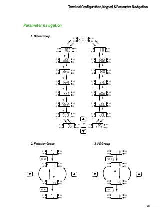
- 1. Parameter navigation 1. Drive Group 2. Function Group 3. I/O Group Terminal Configuration,Keypad & Parameter Navigation SET RUN FWD REV SET RUN FWD REV SET RUN FWD REV SET RUN FWD REV FUNC FUNC I 0 I 0 I 0 SET RUN FWD REV SET RUN FWD REV SET RUN FWD REV SET RUN FWD REV FUNC FUNC FU I F O FU I SET RUN FWD REV SET RUN FWD REV SET RUN FWD REV SET RUN FWD REV SET RUN FWD REV SET RUN FWD REV SET RUN FWD REV SET RUN FWD REV SET RUN FWD REV SET RUN FWD REV SET RUN FWD REV SET RUN FWD REV SET RUN FWD REV SET RUN FWD REV SET RUN FWD REV SET RUN FWD REV SET RUN FWD REV 08
- 2. Program parameter descriptions Code Output Frequency during running, Reference Frequency during stop Acceleration Time Deceleration Time Drive Mode (Run/Stop method) Frequency Mode (Freq. setting method) Step Frequency 1 Step Frequency 2 Step Frequency 3 Output Current Motor Speed DC link Voltage User Display selection Fault Display Motor Direction set FU1 Group selection FU2 Group selection I/O Group selection 0.00 ACC , , 0 to Max. Freq. (FU1-20) 0 to 6000 [sec] 0 to 6000 [sec] 0 (keypad) 1 (Keypad-2) 2 (Fx/Rx-2) 3 (ModBus-RTU) 0 [Keypad-1] 1 (Keypad-2) 2 (V1) 3 (I) 4 (V1+I) 5 (ModBus-RTU) Starting freq (FU1-22) to Max. freq (FU1-20) * [A] * [rpm] * [V] Selected in FU2-73 (User disp) - F (Forward) r (Reverse) 0.01 0.1 0.1 - - 0.01 0.01 0.01 - - - - - 60.00 [Hz]* 10.0 [sec] 10.0 [sec] 1 0 10.00 [Hz] 20.00 [Hz] 30.00 [Hz] - [A] - [rpm] - [V] - nOn F Yes Yes Yes No No Yes - - - - - Yes Description Keypad Display Setting Range Units Factory Default Adjustable during run DRV-00 DRV-01 DRV-02 DRV-03 DRV-04 DRV-05 DRV-06 DRV-07 DRV-08 DRV-09 DRV-10 DRV-11 DRV-12 DRV-13 DRV-20 DRV-21 DRV-22 1. Drive Group [DRV] Jump to desired code # Run Prevention Acceleration Pattern Deceleration Pattern Stop Mode DC Injection Braking Frequency DC Injection Braking On-delay Time DC Injection Braking Voltage Starting DC Injection Braking Time Starting DC Injection Braking Voltage Starting DC Injection Braking Time Maximum Frequency Base Frequency Starting Frequency Frequency Limit selection Low Limit Frequency High Limit Frequency Manual/Auto Torque Boost selection Torque Boost in Forward Direction Torque Boost in Reverse Direction Volts/Hz Pattern User V/F - Frequency 1 User V/F - Voltage 1 User V/F - Frequency 2 User V/F - Voltage 2 User V/F - Frequency 3 User V/F - Voltage 3 User V/F - Frequency 4 User V/F - Voltage 4 Output Voltage Adjustment Energy Save Level F39 Electronic Thermal selection Electronic Thermal Level for 1 minute Electronic Thermal Level for continuous Electronic Thermal Characteristic selection (Motor type) F0 F3 F5 F6 F7 F8 F9 FI0 FII FI2 FI3 F20 F2I F22 F23 F24 F25 F26 F27 F28 F29 F30 F3I F32 F33 F34 F35 F36 F37 F38 F39 F50 F5I F52 F53 1 to 99 0 (None) 1 (Forward Prev) 2 (Reverse Prev) 0 (Linear) 1 (S-curve) 2 (U-curve) 3 (Minimum) 4 (Optimum) 0 (Linear) 1 (S-curve) 2 (U-curve) 3 (Minimum) 4 (Optimum) 0 (Decel) 1 (DC-brake) 2 (Free-run) FU1-22 to 50 [Hz] 0 to 60 [sec] 0 to 200 [%] 0 to 60 [sec] 0 to 200 [%] 0 to 60 [sec] 40 to 400 [Hz] 30 to FU1-20 0.1 to 10 [Hz] 0 (No) 1 (Yes) FU1-22 to FU1-25 FU1-24 to FU1-20 0 (Manual) 1 (Auto) 0 to 15 [%] 0 to 15 [%] 0 (Linear) 1 (Square) 2 (User V/F) 0 to FU1-32 0 to 100 [%] FU1-30 to FU1-20 0 to 100 [%] FU1-32 to FU1-20 0 to 100 [%] FU1-34 to FU1-20 0 to 100 [%] 40 to 110 [%] 0 to 30 [%] 0 (No) 1 (Yes) FU1-52 to 150 [%] 50 to FU1-51 0 (Self-cool) 1 (Forced-cool) 1 0.01 0.01 1 0.1 1 0.1 0.01 0.01 0.01 - 0.01 0.01 - 0.1 0.1 - 0.01 1 0.01 1 0.01 1 0.01 1 0.1 1 - 1 1 - 3 0 0 0 0 5.00 [Hz] 0.5 [sec] 50 [%] 1.0 [sec] 50 [%] 0.0 [sec] 60.00 [Hz]* 60.00 [Hz]* 0.50 [Hz] 0.50 [Hz] 60.00 [Hz]* 0 5.0 [%] 5.0 [%] 0 15.00 [Hz]* 25 [%] 30.00 [Hz]* 50 [%] 45.00 [Hz]* 75 [%] 60.00 [Hz]* 100 [%] 100[%] 0 [%] 0 150 [%] 150 [%] 0 Yes No No No No No No No No No No No No No No No No No No No No No No No No No No No No No Yes Yes Yes Yes Yes FU1-00 FU1-03 FU1-05 FU1-06 FU1-07 FU1-08 FU1-09 FU1-10 FU1-11 FU1-12 FU1-13 FU1-20 FU1-21 FU1-22 FU1-23 FU1-24 FU1-25 FU1-26 FU1-27 FU1-28 FU1-29 FU1-30 FU1-31 FU1-32 FU1-33 FU1-34 FU1-35 FU1-36 FU1-37 FU1-38 FU1-39 FU1-50 FU1-51 FU1-52 FU1-53 2. Function Group1[FU1] 09
- 3. Code Overload Warning Level Overload Warning Hold Time Overload Trip selection Overload Trip level Overload Trip Delay Time Stall Prevention Mode selection Stall Prevention Level Return Code F54 F55 F56 F57 F58 F59 F60 30 to 150 [%] 0 to 30 [sec] 0 (No) 1 (Yes) 30 to 200 [%] 0 to 60 [sec] 000 - 111 (bit set) Bit 0: during Accel. Bit 1: during Steady speed Bit 2: during Decel. 30 to 150 [%] 1 0.1 - 1 1 bit 1 - 150 [%] 10.0 [sec] 1 180 [%] 60.0 [sec] 000 150 [%] - Yes Yes Yes Yes No No - Description Keypad Display Setting Range Units Factory Default Adjustable during run FU1-54 FU1-55 FU1-56 FU1-57 FU1-58 FU1-59 FU1-60 FU1-99 Jump to desired code # Previous Fault History 1 Previous Fault History 2 Previous Fault History 3 Previous Fault History 4 Previous Fault History 5 Erase Fault History Dwell Frequency Dwell Time Frequency Jump selection Jump Frequency 1 Low Jump Frequency 1 High Jump Frequency 2 Low Jump Frequency 2 High Jump Frequency 3 Low Jump Frequency 3 High Input/Output Phase Loss Protection Power ON Start selection Restart after Fault Reset Speed Search selection Current Limit Level during Speed Search P Gain during Speed Search I Gain during speed search Number of Auto Restart Attempt Delay Time before Auto Restart Rated Motor selection Number of Motor Poles Rated Motor Slip Rated Motor Current in RMS No Load Motor Current in RMS Motor Efficiency Load Inertia Carrier Frequency Control Mode selection PID Feedback Signal selection P Gain for PID Control I Gain for PID Control D Gain for PID Control Limit Frequency for PID Control Reference Frequency for Accel and Decel Accel/Decel Time Scale Power On Display H0 HI H2 H3 H4 H5 H6 H7 H8 HI0 HII HI2 HI3 HI4 HI5 HI6 HI9 H20 H2I H22 H23 H24 H25 H26 H27 H30 H3I H32 H33 H34 H36 H37 H39 H40 H50 H5I H52 H53 H54 H70 H7I H72 1 to 99 - 0 (No) 1 (Yes) 0 to FU1-20 0 to 10 [sec] 0 (No) 1 (Yes) FU1-22 to FU2-12 FU1-11 to FU2-20 FU1-22 to FU2-14 FU2-13 to FU1-20 FU1-22 to FU2-16 FU2-15 to FU1-20 00 - 11 (bit set) Bit 0: Output phase loss protection Bit 1: Intput phase loss protection 0 (No) 1 (Yes) 0 (No) 1 (Yes) 0000 - 1111 (bit set) Bit 0: during Accel. Bit 1: after fault reset Bit 2: after instant power failure restart Bit 3: when FU2-20 is set to 1 (Yes). 80 to 200 [%] 0 to 9999 0 to 9999 0 to 10 0 to 60 [sec] 0.4 (0.37kW) 0.8 (0.75kW) 1.5 (1.5kW) 2.2 (2.2kW) 2 to 12 0 to 10 [Hz] 0.1 to 99.9 [A] 0.1 to 99.9 [A] 50 to 100 [%] 0 to 2 1 to 10 [kHz] 0 (V/F) 1 (Slip Compen) 2 (PID) 0 (I) 1 (V1) 0 to 9999 0 to 9999 0 to 9999 0 to FU1-20 0 (Max Freq) 1 (Delta Freq) 0 (0.01 sec) 1 (0.1 sec) 2 (1 sec) 0 (Cmd. Freq) 1 (Acc. Time) 2 (Dec. Time) 3 (Drv mode) 4 (Freq mode) 5 (Step Freq 1) 6 (Step Freq 2) 7 (Step Freq 3) 8 (Current) 9 (Speed) 10(DC link Vtg) 11 (User disp) 12 (Fault Display) 13 (Motor direction) 1 - - 0.01 0.1 - 0.01 0.01 0.01 0.01 0.01 0.01 - - - - 1 1 1 1 0.1 - 1 0.01 1 1 1 1 1 - - 1 1 1 0.01 - - 1 30 0 nOn nOn nOn nOn 0 5.00 [Hz] 0.0 [sec] 0 0.00 [Hz] 0.00 [Hz] 0.00 [Hz] 0.00 [Hz] 0.00 [Hz] 0.00 [Hz] 00 0 0 0000 100 [%] 100 1000 0 1.0 [sec] 4 0 3 kHz 0 0 3000 300 0 60.00 [Hz]* 0 1 0 Yes Yes Yes Yes Yes No No No No No No No No No Yes Yes Yes No Yes Yes Yes Yes Yes No No No No No No No Yes No No Yes Yes Yes Yes No Yes Yes FU2-00 FU2-01 FU2-02 FU2-03 FU2-04 FU2-05 FU2-06 FU2-07 FU2-08 FU2-10 FU2-11 FU2-12 FU2-13 FU2-14 FU2-15 FU2-16 FU2-19 FU2-20 FU2-21 FU2-22 FU2-23 FU2-24 FU2-25 FU2-26 FU2-27 FU2-30 FU2-31 FU2-32 FU2-33 FU2-34 FU2-36 FU2-37 FU2-39 FU2-40 FU2-50 FU2-51 FU2-52 FU2-53 FU2-54 FU2-70 FU2-71 FU2-72 3. Function Group2 [FU2] Program Parameter Descriptions 10
- 4. Starvert iG5 Code Description Keypad Display Setting Range Units Factory Default Adjustable during run User Display selection Gain for Motor Speed Display DB(Dynamic Braking)Resistor Mode selection Duty of Dynamic Braking Resistor Software Version 2nd Acceleration Time 2nd Deceleration Time 2nd Base Frequency 2nd V/F Pattern 2nd Forward Torque Boost 2nd Reverse Torque Boost 2nd Stall Prevention Level 2nd Electronic Thermal Level for 1 minute 2nd Electronic Thermal Level for continuous 2nd Rated Motor Current Read Parameters into Keypad from Inverter Write Parameters to Inverter from Keypad Initialize Parameter Parameter Write Protection Return Code H73 H74 H75 H76 H79 H8I H82 H83 H84 H85 H86 H87 H88 H89 H90 H9I H92 H93 H94 0 (Voltage) 1 (Watt) 2 (Torque) 1 to 1000 [%] 0 [None] 1 [None] 2 (Ext.DB-R) 0 to 30 [%] 0 to 6000 [sec] 0 to 6000 [sec] 30 to FU1-20 0 (Linear) 1 (Square) 2 (User V/F) 0 to 15 [%] 0 to 15 [%] 30 to 150 [%] FU2-89 to 150 [%] 50 to FU2-88(maximum 150%) 0.1 to 99.9 [A] 0 (No) 1 (Yes) 0 (No) 1 (Yes) 0 (No) 1 (All Groups) 2 (DRV) 3 (FU1) 4 (FU2) 5 (I/O) 0 to 255 - 1 - 1 - 0.1 0.1 0.01 - 0.1 0.1 1 1 1 0.1 - - - 1 - 0 100 [%] 0 10 [%] . E 5.0 [sec] 10.0 [sec] 60.00 [Hz]* 0 5.0 [%] 5.0 [%] 150 [%] 150 [%] 100 [%] 1.8 [A] 0 0 0 0 1 Yes Yes Yes Yes - Yes Yes No No No No No Yes Yes No No No No Yes Yes FU2-73 FU2-74 FU2-75 FU2-76 FU2-79 FU2-81 FU2-82 FU2-83 FU2-84 FU2-85 FU2-86 FU2-87 FU2-88 FU2-89 FU2-90 FU2-91 FU2-92 FU2-93 FU2-94 FU2-99 Code Description Keypad Display Setting Range Units Factory Default Adjustable during run 4.Input / Output Group [I/0] Jump to desired code # Filtering Time Constant for V1 Signal Input V1 Input Minimum Voltage Frequency corresponding to V1 Input Minimum Voltage V1 Input Maximum Voltage Frequency corresponding to V1 Input Maximum Voltage Filtering Time Constant for I Signal Input I Input Minimum Current Frequency corresponding to I Input Minimum Current I Input Maximum Current Frequency corresponding to I Input Maximum Current Criteria for Analog Input Signal Loss Multi-function Input Terminal 'P1' define 8,9, 15, 20, 21, 22, 23, 24, 25, 26(-Reserved-) Multi-function Input Terminal 'P2' define Multi-function Input Terminal 'P3' define Terminal Input Status Terminal Output Status Filtering Time Constant for Multi-function Input Terminals Jog Frequency setting Step Frequency 4 Step Frequency 5 Step Frequency 6 Step Frequency 7 Acceleration Time 1 for Step Frequency Deceleration Time 1 for Step Frequency Acceleration Time 2 Deceleration Time 2 Acceleration Time 3 Deceleration Time 3 I 0 I I I 2 I 3 I 4 I 5 I 6 I 7 I 8 I 9 I I0 I I I I I2 I I3 I I4 I I5 I I6 I I7 I 20 I 2I I 22 I 23 I 24 I 25 I 26 I 27 I 28 I 29 I 30 1 to 99 0 to 9999 [ms] 0 to I/O-04 0 to FU1-20 I/O-02 to 10 [V] 0 to FU1-20 0 to 9999 [ms] 0 to I/O-09 0 to FU1-20 I/O-07 to 20 [mA] 0 to FU1-20 0 (None) 1 (Half of x1) 2 (Below x1) 0 (Speed-L) 1 (Speed-M) 2 (Speed-H) 3 (XCEL-L) 4 (XCEL-M) 5 (XCEL-H) 6 (Dc-brake) 7 (2nd Func) 10 (Up) 11 (Down) 12 (3-Wire) 13 (Ext trip-A) 14 (Ext trip-B) 16 (Open-loop) 17 (Main-drive) 18 (Analog hold) 19 (XCEL stop) Same as above Same as above 00000000 - 11111111 (bit set) 0 - 1 (bit set) 2 to 50 FU1-22 to FU1-20 FU1-22 to FU1-20 FU1-22 to FU1-20 FU1-22 to FU1-20 FU1-22 to FU1-20 0 to 6000 [sec] 0 to 6000 [sec] 0 to 6000 [sec] 0 to 6000 [sec] 0 to 6000 [sec] 0 to 6000 [sec] 1 1 0.01 0.01 0.01 0.01 1 0.01 0.01 0.01 0.01 - - - - - - 1 0.01 0.01 0.01 0.01 0.1 0.1 0.1 0.1 0.1 0.1 0.1 1 1,000 [ms] 0.00 [V] 0.00 [Hz] 10.00 [V] 60.00 [Hz]* 1,000 [ms] 4.00 [mA] 0.00 [Hz] 20.00 [mA] 60.00 [Hz]* 0 0 1 2 - - 15 10.00 [Hz] 40.00 [Hz] 50.00 [Hz] 40.00 [Hz] 30.00 [Hz] 20.0 [sec] 20.0 [sec] 30.0 [sec] 30.0 [sec] 40.0 [sec] 40.0 [sec] Yes Yes Yes Yes Yes Yes Yes Yes Yes Yes Yes Yes No No No - - Yes Yes Yes Yes Yes Yes Yes Yes Yes Yes Yes Yes I/O-00 I/O-01 I/O-02 I/O-03 I/O-04 I/O-05 I/O-06 I/O-07 I/O-08 I/O-09 I/O-10 I/O-11 I/O-12 I/O-13 I/O-14 I/O-15 I/O-16 I/O-17 I/O-20 I/O-21 I/O-22 I/O-23 I/O-24 I/O-25 I/O-26 I/O-27 I/O-28 I/O-29 I/O-3011
- 5. Code Description Keypad Display Setting Range Units Factory Default Adjustable during run Acceleration Time 4 Deceleration Time 4 Acceleration Time 5 Deceleration Time 5 Acceleration Time 6 Deceleration Time 6 Acceleration Time 7 Deceleration Time 7 FM (Frequency Meter) Output selection FM Output Adjustment Frequency Detection Level Frquency Detection Bandwidth Multi-function Output define (MO)15, 16, 18, 19, 20(-Reserved-) Fault Output Relay setting (30A, 30B, 30C) Inverter Number Baud Rate I47 Operating selection at Loss of Freq. Reference Waiting Time after Loss of Freq. Reference Communication Protocol selection Return Code I 3I I 32 I 33 I 34 I 35 I 36 I 37 I 38 I 40 I 4I I 42 I 43 I 44 I 45 I 46 I 47 I 48 I 49 I 50 0 to 6000 [sec] 0 to 6000 [sec] 0 to 6000 [sec] 0 to 6000 [sec] 0 to 6000 [sec] 0 to 6000 [sec] 0 to 6000 [sec] 0 to 6000 [sec] 0 (Frequency) 1 (Current) 2 (Voltage) 3 (DC link Vtg) 10 to 200 [%] 0 to FU1-20 0 to FU1-20 0 (FDT-1) 1 (FDT-2) 2 (FDT-3) 3 (FDT-4) 4 (FDT-5) 5 (IOL) 6 (IOL) 7 (Stall) 8 (OV) 9 (LV) 10 (OH) 11 (Lost Command) 12 (Run) 13 (Stop) 14 (Steady) 17 (Search) 000 - 111 (bit set) Bit 0: LV Bit 1: All Trip Bit 2: Auto retry 1 to 32 0 (1200 bps) 1 (2400 bps) 2 (4800 bps) 3 (9600 bps) 4 (19200 bps) 0 (None) 1 (FreeRun) 2 (Stop) 0.1 to 120 [sec] 0 (LG- BUS) 1~6(ModbusASCII) 7~9 (Modbus-RTU) 0.1 0.1 0.1 0.1 0.1 0.1 0.1 0.1 - 1 0.01 0.01 - - 1 - - 0.1 - 50.0 [sec] 50.0 [sec] 40.0 [sec] 40.0 [sec] 30.0 [sec] 30.0 [sec] 20.0 [sec] 20.0 [sec] 0 100 [%] 30.00 [Hz] 10.00 [Hz] 12 010 1 3 0 1.0 [sec] 7 1 Yes Yes Yes Yes Yes Yes Yes Yes Yes Yes Yes Yes Yes Yes Yes Yes Yes Yes Yes Yes I/O-31 I/O-32 I/O-33 I/O-34 I/O-35 I/O-36 I/O-37 I/O-38 I/O-40 I/O-41 I/O-42 I/O-43 I/O-44 I/O-45 I/O-46 I/O-47 I/O-48 I/O-49 I/O-50 I/O-99 Note: Parameters that are set by bit are ON (1) when the upper LED is lit. (F59, H19, H22, I15, I16, I45 are the parameters that are set by bit.) Note: *marked default value changes depend on the main frequency setting in factory(50 / 60Hz) 4.5 4.5 W2 4.5 H24D1 W1 iG5 VARIABLE FREQUENCY DRIVER CAUTION Read the manual and follow the safety instruction before installation or operation Do not the power supply to the drive output terminal (U, V, W) Before opening the cover, disconnect all power and wait at least 3 minutes untill DC bus capacitors discharge. `Risk of Electric Shock`-more than one disconnect switch is required to de - energize the equipment before servicing. SOURCEAC200-230V50/60Hz OUTPUTCAPACITY1.5kVA CURRENT5A FRCQUENCY0.2-400Hz SV015IG5-2 InternationalsystemCo,LtdMadeInKorea 00.00 FUNC RUN STOP RESET Dimension : mm(inch) Inverter SV004iG5-1 SV004iG5-2 SV008iG5-1 SV008iG5-2 SV015iG5-1 SV015iG5-2 SV022iG5-2 SV037iG5-2 SV040iG5-2 SV004iG5-4 SV008iG5-4 SV015iG5-4 SV022iG5-4 SV037iG5-4 SV040iG5-4 0.5 0.5 1 1 2 2 3 5 5.4 0.5 1 2 3 5 5.4 100(3.94) 100(3.94) 130(5.12) 100(3.94) 150(5.90) 130(5.12) 150(5.90) 150(5.90) 150(5.90) 130(5.12) 130(5.12) 130(5.12) 150(5.90) 150(5.90) 150(5.90) 88(3.46) 88(3.46) 118(4.65) 88(3.46) 138(5.43) 118(4.65) 138(5.43) 138(5.43) 138(5.43) 118(4.65) 118(4.65) 118(4.65) 138(5.43) 138(5.43) 138(5.43) 128(5.04) 128(5.04) 128(5.04) 128(5.04) 128(5.04) 128(5.04) 128(5.04) 128(5.04) 128(5.04) 128(5.04) 128(5.04) 128(5.04) 128(5.04) 128(5.04) 128(5.04) 117.5(4.63) 117.5(4.63) 117.5(4.63) 117.5(4.63) 117.5(4.63) 117.5(4.63) 117.5(4.63) 117.5(4.63) 117.5(4.63) 117.5(4.63) 117.5(4.63) 117.5(4.63) 117.5(4.63) 117.5(4.63) 117.5(4.63) 130.9(5.15) 130.9(5.15) 150.9(5.94) 130.9(5.15) 155(6.10) 150.9(5.94) 155(6.10) 155(6.10) 155(6.10) 150.9(5.94) 150.9(5.94) 150.9(5.94) 155(6.10) 155(6.10) 155(6.10) HP W1 W2 H1 H2 D1 Dimension 12
- 6. 1. Standard application Options Drive Resistor capacity [W] Average braking torque[%] Resistor value[ ] Enable duty[%] Continuous braking time[sec] 100 100 100 100 100 100 100 100 100 100 100 100 100 100 100 100 100 100 100 100 100 100 100 100 100 100 100 100 100 100 400 200 100 400 200 100 60 40 40 1800 900 450 300 200 200 5 5 3 5 5 3 2 2 2 5 5 3 2 2 2 5 5 5 5 5 5 5 5 5 5 5 5 5 5 5 SV004iG5-1 SV008iG5-1 SV015iG5-1 SV004iG5-2 SV008iG5-2 SV015iG5-2 SV022iG5-2 SV037iG5-2 SV040iG5-2 SV004iG5-4 SV008iG5-4 SV015iG5-4 SV022iG5-4 SV037iG5-4 SV040iG5-4 2.When the braking magnitude is high Drive Resistor capacity [W] Average braking torque[%] Resistor value[ ] Enable duty[%] Continuous braking time[sec] 100 100 200 100 100 200 300 500 500 100 100 200 300 500 500 100 100 100 100 100 100 100 100 100 100 100 100 100 100 100 400 200 100 400 200 100 60 40 40 1800 900 450 300 200 200 5 5 5 5 5 5 5 5 5 5 5 5 5 5 5 5 5 5 5 5 5 5 5 5 5 5 5 5 5 5 SV004iG5-1 SV008iG5-1 SV015iG5-1 SV004iG5-2 SV008iG5-2 SV015iG5-2 SV022iG5-2 SV037iG5-2 SV040iG5-2 SV004iG5-4 SV008iG5-4 SV015iG5-4 SV022iG5-4 SV037iG5-4 SV040iG5-4 Drive Resistor capacity [W] Average braking torque[%] Resistor value[ ] Enable duty[%] Continuous braking time[sec] 150 150 300 150 150 300 400 600 600 150 150 300 400 600 600 150 150 150 150 150 150 150 150 150 150 150 150 150 150 150 300 150 60 300 150 60 50 33 33 1200 600 300 200 130 130 5 5 5 5 5 5 5 5 5 5 5 5 5 5 5 5 5 5 5 5 5 5 5 5 5 5 5 5 5 5 SV004iG5-1 SV008iG5-1 SV015iG5-1 SV004iG5-2 SV008iG5-2 SV015iG5-2 SV022iG5-2 SV037iG5-2 SV040iG5-2 SV004iG5-4 SV008iG5-4 SV015iG5-4 SV022iG5-4 SV037iG5-4 SV040iG5-4 Peripheral devices Drive Models kW MCCB, ELB Magnetic Contactor AC Input Wire, mm2(AWG) R,S,T U,V,W AC Reactor DC Reactor 0.37 0.75 1.5 0.37 0.75 1.5 2.2 3.7 4 0.37 0.75 1.5 2.2 3.7 4 10A 10A 10A 10A 10A 15A 25A 40A 40A 6A 6A 10A 10A 20A 20A 2(14) 2(14) 2(14) 2(14) 2(14) 2(14) 2(14) 3.5(12) 3.5(12) 2(14) 2(14) 2(14) 2(14) 2(14) 2(14) 2(14) 2(14) 2(14) 2(14) 2(14) 2(14) 2(14) 3.5(12) 3.5(12) 2(14) 2(14) 2(14) 2(14) 2(14) 2(14) 3.5(12) 3.5(12) 3.5(12) 3.5(12) 3.5(12) 3.5(12) 3.5(12) 3.5(12) 3.5(12) 2(14) 2(14) 2(14) 2(14) 2(14) 2(14) Ground ABS33a, EBS33 ABS33a, EBS33 ABS33a, EBS33 ABS33a, EBS33 ABS33a, EBS33 ABS33a, EBS33 ABS33a, EBS33 ABS33a, EBS33 ABS33a, EBS33 ABS33a, EBS33 ABS33a, EBS33 ABS33a, EBS33 ABS33a, EBS33 ABS33a, EBS33 ABS33a, EBS33 SMC-10P SMC-10P SMC-10P SMC-10P SMC-10P SMC-10P SMC-15P SMC-20P SMC-20P SMC-10P SMC-10P SMC-10P SMC-20P SMC-20P SMC-20P 2.13mH, 5.7A 2.13mH, 5.7A 2.13mH, 5.7A 2.13mH, 5.7A 2.13mH, 5.7A 1.20mH, 10A 0.88mH, 14A 0.56mH, 20A 0.56mH, 20A 8.63mH, 2.8A 8.63mH, 2.8A 4.81mH, 4.8A 3.23mH, 7.5A 2.34mH, 10A 2.34mH, 10A 7.00mH, 5.4A 7.00mH, 5.4A 7.00mH, 5.4A 7.00mH, 5.4A 7.00mH, 5.4A 4.05mH, 9.2A 2.92mH, 13A 1.98mH, 19A 1.98mH, 19A 28.62mH, 2.7A 28.62mH, 2.7A 16.14mH, 4.6A 11.66mH, 7.1A 7.83mH, 10A 7.83mH, 10A SV004iG5-1 SV008iG5-1 SV015iG5-1 SV004iG5-2 SV008iG5-2 SV015iG5-2 SV022iG5-2 SV037iG5-2 SV040iG5-2 SV004iG5-4 SV008iG5-4 SV015iG5-4 SV022iG5-4 SV037iG5-4 SV040iG5-4 Option Description DIN Rail base Remote keypad mounting fixture and cable Din rail mounting plate 2 meter, 3 meter and 5 meter cable and mounting fixture. Starvert iG5 Dynamic Braking(DB) Resistors 13
- 7. FF Series (Footprint) FF Series (Footprint) FE Series (Standard) FS Series (output chokes)FE Series (Standard) RFI Filters DB Resistor,Options & Peripheral Devices Drive Models Power Code Current Tension Voltage Leakage Current Dimensions L W H Mounting Y X Output Chokes Weight Mount 0.4kW 0.8kW 1.5kW 0.4kW 0.8kW 1.5kW 2.2kW 3.7kW 4.0kW 0.4kW 0.8kW 1.5kW 2.2kW 3.7kW 4.0kW 173.5 X 103.5 X 40 173.5 X 133.5 X 40 173.5 X 153.5 X 40 173.5 X 103.5 X 40 173.5 X 133.5 X 40 173.5 X 153.5 X 40 173.5 X 133.5 X 40 173.5 X 133.5 X 40 159.5 X 80 159.5 X 110 159.5 X 130 159.5 X 80 159.5 X 110 159.5 X 130 159.5 X 110 159.5 X 130 M4 M4 M4 M4 M4 M4 M4 M4 FS-1 FS-1 FS-2 FS-1 FS-2 FS-2 FS-1 FS-2 3.5A 3.5A 3.5A 0.3A 18A 0.3A 18A 0.3A 18A 0.5A 27A 0.5A 27A 250VA 250VA 250VA 250VA 250VA 250VA 380VAC 380VAC 10A 11A 20A 5A 12A 20A 6A 11A FFG5-M010-1 FFG5-M011-1 FFG5-M020-1 FFG5-T005-1 FFG5-T012-1 FFG5-T020-1 FFG5-T006-1 FFG5-T011-1 SINGLEPHASE (max.) SV004iG5-1 SV008iG5-1 SV015iG5-1 THREEPHASE (max.) SV004iG5-2 SV008iG5-2 SV015iG5-2 SV022iG5-2 SV037iG5-2 SV040iG5-2 SV004iG5-4 SV008iG5-4 SV015iG5-4 SV022iG5-4 SV037iG5-4 SV040iG5-4 IG5 Series Footprint Filter Drive Models Power Code Current Tension Voltage Leakage Current Dimensions L W H Mounting Y X Output Chokes Weight Mount 0.4kW 0.8kW 1.5kW 0.4kW 0.8kW 1.5kW 2.2kW 3.7kW 4.0kW 0.4kW 0.8kW 1.5kW 2.2kW 3.7kW 4.0kW 150.5 X 55 X 45 150.5 X 55 X 45 250 X 110 X 60 250 X 110 X 60 270 X 140 X 60 250 X 110 X 60 250 X 110 X 60 140 X 45 140 X 45 238 X 76 238 X 76 258 X 106 238 X 76 238 X 76 --- --- --- --- --- --- --- FS-1 FS-2 FS-2 FS-2 FS-2 FS-2 FS-2 3.5A 3.5A 0.3A 18A 0.3A 18A 0.3A 18A 0.5A 27A 0.5A 27A 250VA 250VA 250VA 250VA 250VA 380VAC 380VAC 10A 15A 6A 12A 20A 6A 12A FEG5-T010-(X) FEG5-T015-(X) FEG5-T006-(X) FEG5-T012-(X) FEG5-T020-(X) FEG5-T006-(X) FEG5-T012-(X) SINGLEPHASE (max.) SV004iG5-1 SV008iG5-1 SV015iG5-1 THREEPHASE (max.) SV004iG5-2 SV008iG5-2 SV015iG5-2 SV022iG5-2 SV037iG5-2 SV040iG5-2 SV004iG5-4 SV008iG5-4 SV015iG5-4 SV022iG5-4 SV037iG5-4 SV040iG5-4 IG5 Series Standard Filter (X) (1) Industrial environment EN 50081-1 (A class) (2) Domestic and industrial environment EN 50081-1 (B class) H H W X Y L W X Y L RED CARGA MOTOR INVERTER FILTER SHIELDED CABLE INVERTER FILTER SHIELDED CABLE MOTOR W X Y HD Type FS-1 FS-2 FS-3 FS-4 D 21 28.5 48 58 W 85 105 150 200 H 46 62 110 170 X 70 90 125 x 30 180 x 45 O 5 5 5 5 14
- 8. LG constantly endeavor to improve our products so that information in this catalog is subject to change without notice. HEAD OFFICE LG TWIN TOWERS, 20 Yoido-dong, Youngdungpo-gu, Seoul, 150-721, Korea. Tel.(82-2)3777- 4640 ~ 4649 Fax.(82-2)3777- 4648 http://www.lgis.com http://www.fasolution.com OVERSEAS BRANCHES Beijing Tel.86-10-6462-3254, 3256, 3259, 6464-8637 Shanghai Tel.86-21-6252-3367, 3795, 6240-3477 Hanoi Tel.84-4-882-0222 Dalian Tel.86-411-730-6495, 730-7580 Tokyo Tel.81-3-3582-9126 Jakarta Tel.62-21-897-4311 New Jersey Tel.1-201-816-2982