SlideShare a Scribd company logo
1 of 16
Download to read offline
1 of 16
PAPER-I
1. A charge distribution is shown in the given
figure:
Which of the following expressions for the
displacement flux density D due to the
given charge distribution is correct?
1. 0 xD ai for x a   
2.  0 0xD x a i for a x     
3.  0 0xD x a i for x a    
4. 0 xD ai for x a  
Select the correct answer using the codes
given below:
a. 1 and 4
b. 2 and 3
c. 1,2 and 3
d. 2,3 and 4
2. Two concentric metallic spheres of radii ‘a
and ‘b’ carry charges + Q and – Q
respectively as shown in the given figure.
Potential at the centre ‘P will be
a. Zero
b.
04
Q
b 
c.
04
Q
a


d.
0
1 1
4
Q
a b
 
 
  
3. An infinite plane surface carries a uniform
charge density p/m2
as shown in the figure.
The electric field Eat any point Z is given
by
a.
0 | |
z
Z
E a
Z



 
b.
0
0 0, 0
| |
z
Z
E a Z Z
Z

   

 
c.
0
| | 0 0, 0
| |
z
Z
E a Z Z
Z

   

 
d.
0
0
| |
, 0
| |
, 0
0, 0
z
z
Z
E a Z
Z
Z
a Z
Z
Z


 

  

 
 

4. A magnetic field B and an electric field E
are at right angles to each other along the
y-axis and x = axis respectively as shown
in the given figure. the path of an electron
which starts at the origin will be
a. Straight along the y-axis
b. Cycloidal along the x-axis
c. Straight along the z-axis
d. Cycloidal along the z-axis
5. An infinitely long conductor carrying a
current I in a region permeability 1 and
in the vicinity of another region of
permeability 1 is shown in the given
figure for calculating the field in the first
region, the effect of discontinuity is
replaced by an image I’ and with 1 2 
I.E.S-(OBJ) 1997
EELLEECCTTRRIICCAALL EENNGGIINNEEEERRIINNGG
www.estudentzone.comwww.estudentzone.com
2 of 16
which one of the following statements is
correct in this regard?
a. I and I’ have the same strength and
direction
b. I and I’ have opposite direction but the
same strength
c. 1 and I’ have the same direction but
different strength
d. I and I’ have opposite direction and
different strength
6. The image of the dipole of moment P in
the grounded sphere shown in the given
figure is
a. A dipole of moment P
b. A dipole of moment PR/d
c. A dipole of moment PR2
/d2
d. Not a dipole
7. If two concentric square loops A and B
shown in the given figure carry equal
currents in the same sense, then the
magnetic field at ‘O due to the two loops
A and B will be in the ratio
a. 1: 2
b. 1 : 1
c. 2 :1
d. 2 : 1
8. Match List-I (Phenomena) with List-Il
(Reasons) and select the correct answer
using the codes given below the lists:
List I
A. Force on a unit north pole due to
current
B. Flux density intensity relation in a
magnetic material
C. Force of attraction between a current
carrying conductor and a magnetic slab
D. Identically zero magnetic field outside
a coaxial cable
List II
1. Magnetic Polarization
2. Maximization of magnetic lines of
force
3. Work done along a closed path is equal
to total current flow
4. Force between magnetic elements
A B C D
a. 3 1 2 4
b. 4 1 2 3
c. 3 2 1 4
d. 4 2 1 3
9. Two point charges Q and – Q are located
on the surface of a sphere of radius R as
shown in the figure. The average electric
field in the volume of the sphere is
a. Infinite
b.  2
0
2
4
Q
n
R



c.  2
0
2
4
Q
n
R



d. Zero
10. A flat slab of, dielectric ( 5r  )is placed
normal to a uniform field with a flux
density D = 1 Coulomb/m2
. The slab is
uniformly polarized. Polarization V in the
slab (in Coulomb/m2
) will be
a. 0.8
b. 1.2
c. 4.0
d. 6.0
11. A parallel plate capacitor with air as
dielectric is charged and then disconnected
from the supply. The force between the
plates is F. If the cap actor is now
immersed in a liquid dielectric of dielectric
constant e, then the force between the
plates will be
a. 2
F
b. F
c. F
d. /F 
12. Match List-I with List-II and select the
correct answer using the codes given
below the Lists: (Symbols have the usual
meanings)
www.estudentzone.comwww.estudentzone.com
3 of 16
List I
A. Poisson’s equation
B. Laplace’s equation
C. Joule’s equation
D. Helmholtz’s equation
List II
1. 2
0 
2. 2 2
0 0E K E   where 0 0 0K   
3. 2
0

  

4. .j
dP
U E J
dV
 
A B C D
a. 2 1 4 3
b. 3 4 1 2
c. 3 1 4 2
d. 2 4 1 3
13. A circular loop has its radius increasing at
a rate of 2m/s. The loop is placed
perpendicular to a constant magnetic field
of 0.1 Wb/m2
. When the radius of the loop
is 2 m, the emf induced in the loop will be
a. 0.8 V
b. 0.4 V
c. 0.2 V
d. Zero
14. Kirchhoff’s current law for direct currents
is implicit in the expression
a. .V D 

b. . 0J n ds 

c. . 0V B 

d.
D
H J
t

  

15. A rectangular loop in the x-z plane
bounded by the lines x = 0, x = a, z = 0
and z = b, is in a time-varying magnetic
field given by
0 cos yB B t a
Where B0 is a constant,  is the angular
frequency and ay is the unit vector in the
y– direction, the emf induced in the loop is
given by
a. 0 cosabB t
b. 0 sinabB t 
c. 0 sinB t 
d. Zero
16. In a broadside array, the maximum
radiation
a. Occurs at 90° to the line of the array
b. Occurs at 450 to the line of the array
c. Occurs along the line of the array
d. Could occurat any angle to the line of
the array
17. At a certain frequency ‘f’ a uniform plane
wave is found to have established a
wavelength  in a good conductor. Of the
source frequency is doubled, then the
wavelength would change to
a.
2

b. 2
c. 2
d. 4
18. Two loss-less transmission lines 1 and .2
shown in the given figure have each a
characteristic impendence Z. Line 1 is
charged to a voltage of V and line 2 to a
voltage of 2 V. Then both of them are
discharged through resistances Z as
shown. If line 1 gets fully discharged in
time T, then line 2 will fully discharged in
time
a. T/4
b. T/2
c. T
d. 2T
19. As the temperature of a ‘p’ type
semiconductor is gradually and
continuously increased, the Fermi level
will move
a. Into the valence band
b. Into the conduction band
c. Towards the middle of the forbidden
gap
d. Into the region between the acceptor.
level and the valence band
20. Which one of the following polarization
mechanisms/ sets of mechanisms
contribute (s) to the static dielectric
constant of a homopolar neutral dielectric?
a. Electronic
b. Electronic and ionic
c. Electronic, ionic and dipolar
d. Electronic, and dipolar
21. Consider the following materials:
1. Pure silica
2. Bakelite
3. Hard rubber
4. Paraffin
www.estudentzone.comwww.estudentzone.com
4 of 16
The correct sequence of the
DECREASING order of loss angle (60
Hz) these dielectric materials is
a. 1, 2, 3, 4
b. 1, 4, 3, 2
c. 4, 1, 2, 3
d. 4, 3, 1, 2
22. Which one of the following materials is
piezoelectric?
a. Pb2Au
b. Ba Ti O3
c. Mg A12O4
d. Ni Fe2O4
23. The residual resistivity of metals
a. Is essentially independent of
temperature
b. Increase linearly with increasing
temperature
c. Decrease linearly with increasing
temperature
d. Initially increases linearly with
temperature and then remains constant.
24. Consider the following metals:
1. Zinc.
2. Gold.
3. Silver.
4. Copper.
The correct sequence of the increasing
order of their resistivities is
a. 4, 3, 1, 2
b. 3, 4, 2, 1,
c. 4, 3, 2, 1
d. 3, 4, 1, 2
25. Match List-I with List-II and select the
correct answer:
List I (Class of material)
A. Ferromagnetio
B. Superconductor
C. Semiconductor
D. Piezoelectric
List II (Material)
1. YBa2 Cu2 O7
2. LiNbO3
3. Co
4. InGaAsP
A B C D
a. 3 1 2 4
b. 3 1 4 2
c. 1 3 2 4
d. 1 3 4 2
26. A type I superconductor maintained at a
temperature T<Tc is subjected to a
magnetic field H<Hc. The superconductor
will exhibit
a. Perfect diamagnetism
b. Partial diamagnetism
c. Perfect paramagnetism
d. Partial paramagnetism
27. The magnetic susceptibility of a
paramagnetic material is
a. Less than zero
b. Less than one but positive
c. Greater than one
d. Equal to zero
28. Magnetostriction is phenomenon whereby
the magnetization of a ferromagnetic
material leads to a change in
a. Relative permeability
b. Physical dimensions
c. Spontaneous magnetization
d. Magnetic susceptibility
29. Match List - I with List-Il and select the
correct answer
List I (Type of magnetic material)
A. Ferromagnetic
B. Anti-ferromagnetic
C. Ferromagnetic
List II (Orientation of individual dipole
moments)
1.    
2.    
3.    
4.    
A B C
a. 4 2 1
b. 1 2 4
c. 2 1 3
d. 4 2 3
30. Match List-I with List-LI and select the
correct answer
List I (Application)
A. Power transformer
B. Audio transformer
C. Pulse transformer
D. Welding transformer
List II (Core material)
1. Si-Fe alloy
2. Permalloy
3. Ferrite
4. Supermalloy
5. Hypersil
A B C D
a. 1 2 4 5
b. 2 3 4 5
c. 1 2 3 4
d. 2 3 5 4
31. Two initially identical samples A and B of
pure germanium are doped with donors to
www.estudentzone.comwww.estudentzone.com
5 of 16
concentrations of l  1020
m-3
and 3 l020
m -3
respectively. If the hole concentration
in A is 9 1012
m-3
, then the hole
concentration in B at the same temperature
will be
a. 12 3
3 10 m

b. 12 3
7 10 m

c. 12 3
11 10 m

d. 12 3
27 10 m

32. Consider the following statements:
Pure germanium and pure silicon are
examples of
1. Direct band-gap semiconductors.
2. Indirect band-gap semiconductors.
3. Degenerate semiconductors.
Of these statements
a. 1 alone is correct
b. 2 alone is correct
c. 3 alone is correct
d. 1 and 3 are correct
33. Consider the following statements:
In a semiconductor, the measurement of
Hall coefficient provides quantitative
information on
1. Density of carriers.
2. Polarity of carriers.
3. Effective mass of the carriers.
4. Mobility of the carriers.
Of these statements
a. 1 and 2 are correct
b. 2 and 3 are correct
c. 1 and 3 are correct
d. 1, 2, 3 and 4 are correct
34. Silicon carbide reinforced aluminum metal
matrix- composites find application in
a. The manufacture of transformer cores
b. The manufacture of cutting tools.
c. The manufacture of standard resistors
d. Aerospace industry
35. GaAsLEDs emit radiation in the
a. Ultra-violet region
b. Violet-blue-green range of the visible
region
c. Visible region
d. Infra-red region
36. A series RLC circuit, consisting of R = 10
ohms, XL = 20 ohms and Xc = 20 ohms is
connected across an ac supply of 100 V
(rms). The magnitude and phase angle
(with reference to supply voltage) of the
voltage across the inductive coil are
respectively
a. 100 V; 90°
b. 100 V; 900
c. 200 V; – 90°
d. 200 V; 90°
37. From a sinusoidal voltage source Vs of
impedance s s sZ R jX  , power is drawn
by a load L L LZ R jX  .The condition for
maximum power in ZL is given in List – II
for the constraints shown in List – I. Match
List - I with List - II and select the correct
answer using the codes given below the
Lists:
List I
A. Xs = zero
B. XL = zero
C. RL fixed
D. XL fixed
List II
1. 2 2 2
L S sZ R X 
2. L L sZ R jX 
3. L s sZ R jX 
4. L sZ R
5.  
1/222
L S s L LZ R X X jX    
 
A B C D
a. 4 1 2 3
b. 2 3 4 5
c. 4 1 2 5
d. 1 3 4 5
38. For the networks shown in figures A and B
to be duals, it is necessary that R, L’ and C
are respectively equal to
a. 1/R, C and L
b. 1/R, I/L and 1/C
c. 1/ R, 1/L and C
d. R, L and C
39. The impedance Z (s) of the one-port
network shown in the figure is given by
www.estudentzone.comwww.estudentzone.com
6 of 16
a.
2 1
1
RL
s s
C LC
s
LC
 

b.
2 1 2 1 2
2 2
2
1
L R R C R R
s s
R LC R LC
L
s
R C
 
 

c.
2 1
1 2
1
1
RL C
s s
R R LC
L
s
R C

 

d.
2 2 1 2
1 1
1
1
L R C R R
s s
R LC R LC
s
R C
 
 

40. Which of the following statement (s) is/are
true of the circuit shown in the given
figure?
1. It is a first order circuit with steady-
state values of
5 5
,
3 3
V V I A 
2. It is a second order circuit with steady
state values of V = 1 V; I =1 A
3. The network function V(s) /I(s) has
one pole.
4. The network function V (s) /I(s) has
two poles.
Select the correct answer using the codes
given below:
a. 1 and 3
b. 2 and 4
c. 2 alone
d. 1 alone
41. In addition to the condition that Y (s) is
real when ‘s’ is real, for an admittance
function Y (s) to be positive real, which of
the following conditions are to be
satisfied?
1.  Re 0 Re 0Y s for s 
2.  Re 0 Re 0Y s for s 
3.  | | | | | | / 2Arg Y s Arg s for Arg s  
4.  | | | | | | / 2Arg Y s Arg s for Arg s  
Select the correct answer using the codes
given below:
a. 1 and 3 are correct
b. 1 and 4 are correct
c. 2 and 3 are correct
d. 2 and 4 are correct
42. The circuit shown in the given figure is in
steady-state with, switch ‘S’ open. The
switch is closed at t = 0. The values of
 0cV 
and  cV  will be respectively
a. 2 V, 0 V
b. 0V,2V
c. 2V,2V
d. 0V,0V
43. After closing the switch ‘S’ at t = 0, the
current i(t) at any instant ‘t’ in the network
shown in the given figure will be
a. 100
10 10 t
e
b. 100
10 10 t
e
c. 100
10 10 t
e

d. 100
10 10 t
e

44. The pole-zero configuration of a network
transfer function is shown in the given
figure. The magnitude of the transfer
function will
a. Decrease with frequency
b. Increase with frequency
c. Initially increase and then decrease
with frequency
d. Be independent of frequency
45. Consider the following statements:
1. The two-port network shown below
does NOT have an impedance matrix
representation.
2. The following two-port network does
NOT have an admittance matrix
representation
www.estudentzone.comwww.estudentzone.com
7 of 16
3. A two-port network is said to be
reciprocal if it satisfies z12 = z21
Of these statements
a. 1 and 2 are correct
b. 1, 2 and 3 are correct
c. 1 and 3 are correct
d. None is correct
46. Match List - I with List - II for the two-
port network shown in the given figure and
select the correct answer.
List I
A. Z11
B. Z12
C. Z21
D. Z22
List II
1. R
2. R+L
3. R-Ls
4. R+Ls
A B C D
a. 1 2 1 4
b. 2 1 1 3
c. 1 1 1 4
d. 2 1 3 4
47. Consider the following statements:
I : Any function in ‘s’ which can be
expressed as a ratio of any two arbitrary
polynomials in ‘scan be realized s a
driving- point function of a passive
network.
II: Any function in ‘s’ which can be
expressed as a ratio of two arbitrary
polynomials in ‘s’, is a positive ,real
function.
Of these statements
a. both I and II are true
b. I is true but 11 is false
c. both I and II are false
d. I is false but II is true
48. Consider the following polynomials:
1. 4 3 2
7 17 17 6s s s s   
2. 4 3 2
11 41 61 30s s s s   
3. 4 3 2
2 3 2s s s s   
Among these polynomials, those which are
Hurwitz would include
a. 1 and 3
b. 2 and 3
c. 1 and 2
d. 1,2 and 3
49. Match List-I with List-II and select the
correct answer:
List I (Function)
A. Unit tamp
B. Unit step
C. Unit impulse
D. Unit doublet
List II (Laplace transform)
1. s
2. 1
3. 1/s
4. 1/s2
A B C D
a. 4 3 2 1
b. 3 4 1 2
c. 4 3 1 2
d. 3 4 2 1
50. A system is represented by
 2 4
dy
y tu t
dt
 
The ramp component in the forced
response will be
a. Tu (t)
b. 2t u(t)
c. 3t u(t)
d. 4t u(t)
51. The Laplace transform of the function i (t)
is:  
  2
0 4
1 4 5
s
I s
s s s s
 

  
its final
value will be
a. 4/5
b. 5/4
c. 4
d. 5
52. If the unit step response of a network is
 1 t
e 
 , then its unit impulse response
will be
a. t
e 
 
b. /t
e 
 
c.
1 t
e 


d.  1 t
e 
 

53. In the network shown in the given figure,
if the voltage v at the time considered is 20
V, then dv/dt at that time will be
www.estudentzone.comwww.estudentzone.com
8 of 16
a. 1 V/s
b. 2 V/s
c. -2 V/s
d. zero
54. Which one of the following pairs of poles
and responses is correctly matched?
Poles Response
a.
b.
c.
d.
55. The impulse response of an R-L circuit is a
a. Rising exponential function
b. Decaying exponential function
c. Step function
d. Parabolic function
56. A pulse of unit amplitude and width ‘a’ is
applied to a series RL circuit as shown in
the figure. The current i (t) as ‘t’ tends to
infinity will be
a. Zero
b. 1 A
c. A value between zero and one
depending upon the width of the pulse
d. Infinite
57. The sinusoidal steady-state voltage gain of
the network shown in the given figure will
have magnitude equal to 0.707 at an
angular frequency of
a. zero
b. RC rad/s
c. 1/RC rad/s
d. 1 rad/s
58. The phase angle of the current ‘I’ with
respect to the voltage V1 in the circuit
shown in the figure is:
a. 0°
b. +45°
c. – 45°
d. – 90°
59. A second order system is given by
2
2
12 100 0
d y dy
y
dt dt
  
The damped natural frequency in rad/sec is
a. 100
b. 10
c. 44
d. 8
60. An alternator is delivering power to a
balanced load at unity power factor. The
phase angle between the line voltage and
the line current is
a. 90°
b. 60°
c. 30°
d. 0°
61. Eoa EOb and Eoc are three phase voltages
while Eab , Ebc and Eca are the line voltage
of a balanced three-phase system having a-
b-c phase sequence. In relation to Eoc Ebc
would
a. Lag by 30°
b. Lead by 30°
c. Have the same phase
d. Have no definite phase relationship
62. For loop 1 of the network shown in the
given figure, the correct loop equation is:
www.estudentzone.comwww.estudentzone.com
9 of 16
a.
       
 
1 1 1 2
2
12
d
v t Ri t L i t i t
dt
di
M t
dt
    

b.
       
   
1 1 1 2
2 2
12 23
d
v t Ri t L i t i t
dt
di di
M t M t
dt dt
    
 
c.
       
     
2
1 2 1 2 3
2 2
12 23 122
did
L i t i t L L t
dt dt
di di
M M t M t
dt dt

  
  
d.
       
     
2
1 2 1 2 3
1 1
12 12 232
did
L i t i t L L t
dt dt
di di
M t M M t
dt dt

  

  

63. Consider the following statements:
In the circuit shown in the figure, if the
equivalent impedance between x-x is Zeq
then
1. 2 5eqZ j 
2. 2 3eqZ j 
3. 1 2I I 
4. 1 2I I
Of these statements
a. 1 alone is true
b. 2 and 4 are correct
c. 2 and 3 are correct
d. 1 and 4 are correct
64. The residues at the pole of Y (s). of an R–
C network are
a. Real and negative
b. Real and positive
c. Complex with positive real part
d. Complex with negative real part
65. Consider the following statements:
In a measuring instrument,
1. Linearity is more important than
sensitivity
2. High precision indicates high accuracy.
3. Accuracy cannot be better than
resolution.
Of these statements
a. 1, 2, and 3 are correct
b. 1, and 2 are correct
c. 2 and 3 are correct
d. 1 and 3 are correct
66. What voltage would a voltmeter with
impedance 20,000  and range 0–1V
show in the circuit given below?
a. 82 mV
b. 100 mV
c. 118 mV
d. 5V
67. Match List-I with List-II and select the
correct answer:
List I
A. Cesium
B. Manganin
C. Standard voltage
D. IEEE 488
List II
1. Standard resistance
2. Atomic clock
3. Instrument interface
4. Josephson Junction
A B C D
a. 2 1 3 4
b. 2 1 4 3
c. 1 2 3 4
d. 1 2 4 3
68. The limiting errors of measurement of
power consumed by and the current
passing through a resistance are ± 1.5%
and ± 1% respectively: The limiting error
of measurement of resistance will then be
a. ± 0.5%
b. ± 1.0%
c. ± 2.5%
d. ± 3.5%
69. Horizontal deflection in a CRO is due to E
sin t while vertical deflection is due to E
sin  t  with a positive . Consider the
following patterns obtained in the CRO.
www.estudentzone.comwww.estudentzone.com
10 of 16
The correct sequence of these patterns in
increasing order of the value of  is:
a. 3, 2, 5, 1, 4
b. 3, 2, 4, 5, 1
c. 2, 3,5, 1,4
d. 2,3,5,4, 1
70. Which of the following until axe present in
a spectrum analyzer?
1. Mixer.
2. Saw-tooth generator.
3. Local oscillator.
Select the correct answer using the codes
given below:
a. 1, 2 and 3
b. 1 and 2
c. 1 and 3
d. 2 and 3
71. For the voltmeter circuit shown in the
given figure, the basic D’ Arsonval meter
used has full-scale current of 1 mA and
meter resistance (Rm ) of 100 ohms. The
values of the series resistance R1 and R2
required for 10V range and 50 V range
will be respectively
a. 9.9k and 40 k
b. 10 k and 50 k
c. 20 k and 30 k
d. 200 k and 250 k
72. Electronic voltmeter provides ore accurate
readings in high resistance circuits as
compared to a non-electronic voltmeter
because of Its
a. High V/ohm ratings
b. High ohm/ratings
c. High meter resistance
d. Low resolution
73. A current transformer has a phase error of
+ 30.The phase angle between the primary
and secondary currents is
a. 30°
b. 177°
c. 180°
d. 183°
74. Modem electronic multimeters measure
resistance by
a. Using a bridge circuit
b. Using an electronic bridge
compensator for nulling
c. Forcing a constant current and
measuring the voltage across the
unknown resistor
d. Applying a constant voltage and
measuring the current through the
unknown resistor
75. In the case of power measurement by two-
wattmeter method in a balanced 3-phase
system with a pure inductive load,
a. Both the watt meters will indicate the
same value but of opposite sign
b. Both the watt meters will indicate zero
c. Both the watt meters will indicate the
same value and of the same sign
d. One wattmeter will indicate zero and
the other will indicate some non-zero
value
76. Many modem capacitance meters measure
capacitance by making the unknown
capacity an element in a charge amplifier.
A schematic f the same is given below. If
the maximum permissible output voltage is
limited to 1Vpeak’ due to slew rate
constrainst, then the maximum Cx, with be
a. 10 pF
b. 100 pF
c. 1000 pF
d. 10 nF
77. A 230 V, 10 A, single-phase energy meter
makes 90 revolutions in 3 minutes at half
load rated voltage and unity pf. if the
meter constant is 1800 revolution, kWh,
then its error at half load will be
a. 13.04% slow
b. 13.04% fast
c. 15% slow
d. 15% fast
78. A strain gauge bridge measures the strain
in a cantilever where the gauge is fixed.
With strain , the gauge resistance
increases from 110 to 110.520. If the
www.estudentzone.comwww.estudentzone.com
11 of 16
gauge factor is 2.03, then the strain in the
cantilever will be
a. 3
2.06 10

b. 3
3.15 10

c. 3
3.81 10

d. 3
4.33 10

79. Consider the following statements:
The causes of error in the measurement of
temperature using a thermistor are
1. Self heating
2. Poor sensitivity.
3. Non-linear characteristics.
Of these statements
a. 1, 2 and 3 are correct
b. 1 and 2 are correct
c. 2 and 3 are correct
d. 1 and 3 are correct
80. A piezoelectric transducer has the
following parameter values:
Crystal capacitance = 10-9
F
Cable capacitance = 210-10
F
Charge sensitivity = 410-6
Coulomb/cm.
If the oscilloscope used for read-out has an
input resistance of 1 M in parallel with
C = 4  10-10
F, then the voltage sensitivity
constant will be
a. 2500 V/cm
b. 3334 V/cm
c. 4000 V/cm
d. 4500 V/cm
81. For a thermocouple pair (A,B), the
extension wires (C,P)
a. Should be identical pair elements
b. Should ‘have identical temperature -
emf relationship
c. Can be of any tewo dissimilar
materials
d. Should have very small temperature -
emf sensitivity
82. A 7- bit successive approximation DVM
will convert the analog input into digital
output in a period of
a. 7 clock pulses
b. 8 clock pulses
c.
input signal amplitude
7 clock pulses
full-scale output amplitude

d.
input signal amplitude
8 clock pulses
full-scale output amplitude

83. Match List-I with List-Il. and select the
correct answer:
List I
A. Low pass filter
B. High pass filter
C. Band pass filter
D. Band reject filter
List II
1.
1
Ts
Ts
2.
1
1
1 Ts
Ts
 
  
 
3.
1
1
1
sT
Ts
Ts
Ts

 
  
 
4.
1
1 Ts
A B C D
a. 1 4 3 2
b. 4 1 2 3
c. 1 4 2 3
d. 4 1 3 2
84. Data buffering means
a. A buffer stock of data already stored in
a computer unit
b. An electronic circuit which is used to
maintain the level of data
c. That data are first collected in an
external, unit and then processed into
the computer
d. Application of buffer (unity gain
amplifier) at input interface to the
computer
85. A circuit draws a current T’. When a
single-phase ac voltage V is applied to it.
If the power factor is cos then the
dimensions of VI cos would be
a. ML3
T2
b. ML2
T3
c. ML3
T3
d. ML2
T-3
86. Given: KKt = 99 ; s = j1 rad/s, the
sensitivity of the closed-loop, system
(shown in the given figure) to variation in
parameter K is approximately
a. 0.01
b. 0.1.
c. 1.0
www.estudentzone.comwww.estudentzone.com
12 of 16
d. 10
87. The transfer function C/R of the system
shown in the figure is:
a.
 
1 2 2
1 1 2 21
G G H
H G G H
b.
 
1 2
1 1 2 21
G H
H G G H
c.
 
1 2
1 1 2 11
G H
H G G H
d.
 
1 1
2 1 2 21
G H
H G G H
88. The Nyquist plot for a control system is
shown in Figure I. The Bode plot for the
same system will be as in
a.
b.
c.
d.
89. A unity feedback second order control
system is characterized by
 
 
K
G s
s Js B


where J = moment of inertia, K= system
gain B viscous damping coefficient. The
transient response specification which is
NOT affected by variation of system gain
is the
a. Peak overshoot
b. Rise time
c. Settling time
d. Damped frequency of oscillations
90. The root-locus plot for an uncompensated
unstable system is shown in the given
figure. The system is to be compensated
by a compensating zero, .The most
desirable location of the compensating
zero would be the point marked.
a. A
b. B
c. C
d. D.
91. The open-loop transfer function of a unity
feedback control system is
   
  
30
1
G s H s
s s s T

 
where T is a variable parameter. The
closed-loop system will be stable for all
values of
a. T > 0
b. 0 < T < 3
c. T > 5
d. 3 < T < 5
92. The Nyquist plot of the open-loop transfer
function G (s) H(s) is shown in the given
figure. It indicates that
www.estudentzone.comwww.estudentzone.com
13 of 16
a. The open-loop system is unstable but
the closed-loop system is stable
b. Both open-loop and closed-loop
systems are unstable
c. Open-loop system is stable but closed-
loop system is unstable
d. Both open-loop and closed-loop
systems are stable
93. In the control system shown in the given
figure, the controller which can give zero
steady-state error to a ramp input. with K
= 9 is
a. Proportional type
b. Integral type
c. Derivative type
d. Proportional plus derivative type
94. The garn cross-over frequency and band-
width of a control system are cu and bu
respectively. A phase-lag network is
employed for compensating the system. If
the gain cross-over frequency and
bandwidth of the compensated system
are cc and bc respectively, then
a. ;cc cu bc bu    
b. ;cc cu bc bu    
c. ;cc cu bc bu    
d. ;cc cu bc bu    
95. The transfer function of a certain system is
 
  4 3 2
1
5 7 6 3
Y s
U s s s s s

   
The A, B matrix pair of the equivalent
state-space model will be
a.
0 1 0 0 0
0 0 1 0 0
0 0 0 1 0
3 6 7 5 1
   
   
   
   
   
      
b.
0 1 0 0 0
0 0 1 0 0
0 0 0 1 0
3 5 6 7 1
   
   
   
   
   
      
c.
0 1 0 0 1
0 0 1 0 0
0 0 0 1 0
5 7 6 3 0
   
   
   
   
   
      
d.
1 0 0 0 0
0 0 0 0 0
0 0 1 0 0
3 6 7 5 1
   
   
   
   
   
      
96. A liner system is described by the state
equations
1 1
2 2
1 0 0
1 1 1
x x
r
x x
      
       
      
C = x2
where r and c are the input and output
reactively. The transfer function is:
a. 1/ (s+1)
b. 1/(5+1)2
c. 1/ (s-1)
d. 1/ (s-1)2
97. The state equation of a dynamic system is
given by    X t AX t
1 1 0 0 0
0 1 1 0 0
0 0 1 0 0
0 0 6 3 4
0 0 0 4 3
A
 
  
  
 
  
   
The eigenvalues of the system would be
a. Real non-repeated only
b. Real non-repeated and complex
c. Real repeated
d. Real repeated and complex
98. A simple electric water heater is shown in
the given figure. The system can be
modelled by
a. A first order differential equation
b. A second order differential equation
c. A third order differential equation
d. An algebraic equation
www.estudentzone.comwww.estudentzone.com
14 of 16
99. Match List-I with List-Il and select the
correct answer
List I (Properties of frictional force)
A.
B.
C.
List II (Frictional force)
1. Coulomb friction
2. Viscous friction
3. Static friction
A B C
a. 1 2 3
b. 2 1 3
c. 3 2 1
d. 2 3 1
100. Laplace transform of the output response
of a liner system is the system transfer
function when the input is
a. A step signal
b. A ramp signal
c. An impulse signal
d. A sinusoidal signal
101. Match List-I with list-II and select the
correct answer:
List I
A. Hydraulic actuator
B. Flapper valve
C. Potentiometer error detector
D. Dumb-bell rotor
List II
1. Linear device
2. A.C. servo systems
3. Large power to weight ratio
4. Pneumatic systems
A B C D
a. 4 3 2 1
b. 3 4 2 1
c. 3 4 1 2
d. 4 3 1 2
102. Which of the following statements
regarding an ac servo system employing a
synchro error detector are correct?
1. Sensitivity of the error detector is
measured in volts/degree.
2. The transfer function of the synchro
error detector is
r c
E
 
where E =
error voltage, r and c are reference
and controlled shaft positions.
3. Sensitivity of the error detector has the
same sign at the two null positions.
a. 1, 2 and 3
b. 1 and 2
c. 2 and 3
d. 1 and 3
103. Four speed-torque curves (labelled I, II, III
and IV) are shown in the given figure.
That of an ac servomotor will be as in the
curve labelled
a. I
b. II
c. III
d. IV
104. A non-linear control system is described
by the equation
2
2
sin 0
d x
x
dt
 
The type of singularity at x  and
dx
dt
=
0 is:
a. Centre
b. Stable focus
c. Saddle point
d. Stable node
105. Which one of the following pairs of phase-
plane diagram and types of singularities is
NOT correctly matched?
Phase-plane diagram Singularity
a.
b.
www.estudentzone.comwww.estudentzone.com
15 of 16
c.
d.
106. Consider the following state equations for
a discrete system:
 
 
 
 
 1 1
2 2
1
0
1 12
1 1 1 1
4 4
x k x k
u k
x k x k
 
      
              
  
   
 
 
 1
2
1 1 4
x k
y k u k
x k
 
   
 
The system given above is
a. Controllable and observable
b. Uncontrollable and unobservable
c. Uncontrollable and observable
d. Controllable and unobservable
107. Which one of the following systems is
open-loop?
a. The respiratory system of man
b. A system for controlling the movement
of the slide of a copying milling
machine
c. A thermostatic control
d. Traffic light control
108. Assertion A: In general, circulation of the
magnetic field intensity is zero.
Reason R: Vector source of circulation is
the current density.
a. Both A and R are true and R is the
correct explanation of A
b. Both A and R are true but R is NOT a
correct explanation of A
c. A is true but R is false
d. A is false but R is true
109. Assertion A: In some semiconductors, the
Hall coefficient is positive.
Reason R: In these semiconductors, the
mobility of holes is greater than that of
electrons.
a. Both A and R are true and R is the
correct explanation of A
b. Both A and R are true but R is NOT a
correct explanation of A
c. A is true but R is false
d. A is false but R is true
110. Assertion A: Intrinsic germanium does
not show n-type behavior.
Reason R: In intrinsic germanium, the
number of electrons is less than the
number of holes.
a. Both A and R are true and R is the
correct explanation of A
b. Both A and R are true but R is NOT a
correct explanation of A
c. A is true but R is false
d. A is false but R is true
111. Assertion A: Quartz crystal is preferred
over Rochelle salt crystal for commercial
piezoelectric applications.
Reason R: Rochelle salt is mechanically
weaker.
a. Both A and R are true and R is the
correct explanation of A
b. Both A and R are true but R is NOT a
correct explanation of A
c. A is true but R is false
d. A is false but R is true
112. A voltmeter with a resistance of 10 k is
connected with two other 10k resistors
across a 200 V 3 - phase mains, as shown
in the figure:
Assertion A: The voltmeter reading will
be 115 V.
Reason R: The connections are similar to
Scott connection.
a. Both A and R are true and R is the
correct explanation of A
b. Both A and R are true but R is NOT a
correct explanation of A
c. A is true but R is false
d. A is false but R is true
113. Assertion A: The bridge shown in the
figure is balanced by first adjusting R1 for
inductive balance and then adjusting R3 for
www.estudentzone.comwww.estudentzone.com
16 of 16
resistive balance; and this is repeated till
balance is achieved.
Reason R: For medium-Q coils, the
resistance effect is not pronounced and
balance ia reached after a few adjustments.
a. Both A and R are true and R is the
correct explanation of A
b. Both A and R are true but R is NOT a
correct explanation of A
c. A is true but R is false
d. A is false but R is true
114. Assertion A: Electrometers are used at the
output stage of electrode pH meters.
Reason R: In electrode type pH meters,
the potential is measured using reference
and measuring electrodes.
a. Both A and R are true and R is the
correct explanation of A
b. Both A and R are true but R is NOT a
correct explanation of A
c. A is true but R is false
d. A is false but R is true
115. Assertion A: The frequency response
shown in the given figure is that of a
vibration galvanometer.
Reason R: A vibration galvanometer is
the most suitable detector in ac
potentiometer method of measurement.
a. Both A and R are true and R is the
correct explanation of A
b. Both A and R are true but R is NOT a
correct explanation of A
c. A is true but R is false
d. A is false but R is true
116. Assertion A: The solution of
1
3
2
digit
voltmeter is 0.001.
Reason R: Addition of
1
2
digit to a digital
voltmeter increases the range of the meter.
a. Both A and R are true and R is the
correct explanation of A
b. Both A and R are true but R is NOT a
correct explanation of A
c. A is true but R is false
d. A is false but R is true
117. Assertion A: Section AB on the negative
real axis in the given figure lies on the
root-locus.
Reason R: All the points in between A
and B have two poles to the right of the
points.
a. Both A and R are true and R is the
correct explanation of A
b. Both A and R are true but R is NOT a
correct explanation of A
c. A is true but R is false
d. A is false but R is true
118. Assertion A: Feedback control systems
are often compensated by phase
lead/phase-lag networks
Reason R: Phase-lead/phase-lag networks
are easily realizable and obtainable.
a. Both A and R are true and R is the
correct explanation of A
b. Both A and R are true but R is NOT a
correct explanation of A
c. A is true but R is false
d. A is false but R is true
119. Assertion A: A discrete data system
having the characteristic equation
2
1.5 1 0Z Z   is unstable.
Reason R: The negative coefficients of
the characteristic equation in the z-plane
represent an unstable discrete system.
a. Both A and R are true and R is the
correct explanation of A
b. Both A and R are true but R is NOT a
correct explanation of A
c. A is true but R is false
d. A is false but R is true
120. Assertion A: A dipole placed in a uniform
field experiences a torque tending to align
the dipole axis with the field.
Reason R: A dipole placed in a uniform
field does not experience a translational
force.
a. Both A and R are true and R is the
correct explanation of A
b. Both A and R are true but R is NOT a
correct explanation of A
c. A is true but R is false
d. A is false but R is true
www.estudentzone.comwww.estudentzone.com

More Related Content

What's hot

Physics Sample Paper with General Instruction for Class - 12
Physics Sample Paper with General Instruction for Class - 12Physics Sample Paper with General Instruction for Class - 12
Physics Sample Paper with General Instruction for Class - 12Learning Three Sixty
 
UPSEE - Physics -1998 Unsolved Paper
UPSEE - Physics -1998 Unsolved PaperUPSEE - Physics -1998 Unsolved Paper
UPSEE - Physics -1998 Unsolved PaperVasista Vinuthan
 
Class 12 Cbse Physics Sample Paper 2013 Model 1
Class 12 Cbse Physics Sample Paper 2013 Model 1 Class 12 Cbse Physics Sample Paper 2013 Model 1
Class 12 Cbse Physics Sample Paper 2013 Model 1 Sunaina Rawat
 
Ies electrical-engineering-paper-i-2012
Ies electrical-engineering-paper-i-2012Ies electrical-engineering-paper-i-2012
Ies electrical-engineering-paper-i-2012Venugopala Rao P
 
Electrical Engineering - 2007 Unsolved Paper
Electrical Engineering - 2007 Unsolved PaperElectrical Engineering - 2007 Unsolved Paper
Electrical Engineering - 2007 Unsolved PaperVasista Vinuthan
 
IIT JEE - 2008 ii - physics
IIT JEE  - 2008  ii - physicsIIT JEE  - 2008  ii - physics
IIT JEE - 2008 ii - physicsVasista Vinuthan
 
Class 12 Cbse Physics Sample Paper 2010 Model 3
Class 12 Cbse Physics Sample Paper 2010 Model 3Class 12 Cbse Physics Sample Paper 2010 Model 3
Class 12 Cbse Physics Sample Paper 2010 Model 3Sunaina Rawat
 
Electrical Engineering - 2008 Unsolved Paper
Electrical Engineering - 2008 Unsolved PaperElectrical Engineering - 2008 Unsolved Paper
Electrical Engineering - 2008 Unsolved PaperVasista Vinuthan
 
Ec8451 - Electro Magnetic Fields
Ec8451 - Electro Magnetic FieldsEc8451 - Electro Magnetic Fields
Ec8451 - Electro Magnetic FieldsBenesh Selvanesan
 

What's hot (20)

Physics Sample Paper with General Instruction for Class - 12
Physics Sample Paper with General Instruction for Class - 12Physics Sample Paper with General Instruction for Class - 12
Physics Sample Paper with General Instruction for Class - 12
 
nothing
nothingnothing
nothing
 
IITJEE - Physics 2008-i
IITJEE - Physics  2008-iIITJEE - Physics  2008-i
IITJEE - Physics 2008-i
 
IIT JEE Physics 1988
IIT JEE Physics   1988IIT JEE Physics   1988
IIT JEE Physics 1988
 
UPSEE - Physics -1998 Unsolved Paper
UPSEE - Physics -1998 Unsolved PaperUPSEE - Physics -1998 Unsolved Paper
UPSEE - Physics -1998 Unsolved Paper
 
AIPMT Physics 1997
AIPMT Physics   1997AIPMT Physics   1997
AIPMT Physics 1997
 
AIPMT Physics 1995
AIPMT Physics 1995AIPMT Physics 1995
AIPMT Physics 1995
 
11671 physicspaper1
11671 physicspaper111671 physicspaper1
11671 physicspaper1
 
Class 12 Cbse Physics Sample Paper 2013 Model 1
Class 12 Cbse Physics Sample Paper 2013 Model 1 Class 12 Cbse Physics Sample Paper 2013 Model 1
Class 12 Cbse Physics Sample Paper 2013 Model 1
 
Ies electrical-engineering-paper-i-2012
Ies electrical-engineering-paper-i-2012Ies electrical-engineering-paper-i-2012
Ies electrical-engineering-paper-i-2012
 
AIPMT Physics 1994
AIPMT Physics  1994AIPMT Physics  1994
AIPMT Physics 1994
 
IITJEE - Physics 2011-i
IITJEE - Physics   2011-iIITJEE - Physics   2011-i
IITJEE - Physics 2011-i
 
Electrical Engineering - 2007 Unsolved Paper
Electrical Engineering - 2007 Unsolved PaperElectrical Engineering - 2007 Unsolved Paper
Electrical Engineering - 2007 Unsolved Paper
 
IIT JEE - 2008 ii - physics
IIT JEE  - 2008  ii - physicsIIT JEE  - 2008  ii - physics
IIT JEE - 2008 ii - physics
 
IIT JEE Physics 1999
IIT JEE Physics   1999IIT JEE Physics   1999
IIT JEE Physics 1999
 
IIT JEE Physics 1997
IIT JEE Physics   1997IIT JEE Physics   1997
IIT JEE Physics 1997
 
CAT -2010 Unsolved Paper
CAT -2010 Unsolved PaperCAT -2010 Unsolved Paper
CAT -2010 Unsolved Paper
 
Class 12 Cbse Physics Sample Paper 2010 Model 3
Class 12 Cbse Physics Sample Paper 2010 Model 3Class 12 Cbse Physics Sample Paper 2010 Model 3
Class 12 Cbse Physics Sample Paper 2010 Model 3
 
Electrical Engineering - 2008 Unsolved Paper
Electrical Engineering - 2008 Unsolved PaperElectrical Engineering - 2008 Unsolved Paper
Electrical Engineering - 2008 Unsolved Paper
 
Ec8451 - Electro Magnetic Fields
Ec8451 - Electro Magnetic FieldsEc8451 - Electro Magnetic Fields
Ec8451 - Electro Magnetic Fields
 

Similar to Ies obj-electrical engineering-1997 paper-i

UPSEE - Physics -2004 Unsolved Paper
UPSEE - Physics -2004 Unsolved PaperUPSEE - Physics -2004 Unsolved Paper
UPSEE - Physics -2004 Unsolved PaperVasista Vinuthan
 
UPSEE - Physics -2007 Unsolved Paper
UPSEE - Physics -2007 Unsolved PaperUPSEE - Physics -2007 Unsolved Paper
UPSEE - Physics -2007 Unsolved PaperVasista Vinuthan
 
Ies electrical-engineering-paper-1-1997
Ies electrical-engineering-paper-1-1997Ies electrical-engineering-paper-1-1997
Ies electrical-engineering-paper-1-1997Venugopala Rao P
 
Physics sample question paper 2020
Physics sample question paper 2020 Physics sample question paper 2020
Physics sample question paper 2020 piphysicsclasses
 
Physics 22-23.docx
Physics 22-23.docxPhysics 22-23.docx
Physics 22-23.docxPappuPriya
 
Ies electrical-engineering-paper-1-2004
Ies electrical-engineering-paper-1-2004Ies electrical-engineering-paper-1-2004
Ies electrical-engineering-paper-1-2004Venugopala Rao P
 
Ies electrical-engineering-2011
Ies electrical-engineering-2011Ies electrical-engineering-2011
Ies electrical-engineering-2011Venugopala Rao P
 
physics-class-xii-sample-paper-test-01-for-board-exam-2023-answers.pdf
physics-class-xii-sample-paper-test-01-for-board-exam-2023-answers.pdfphysics-class-xii-sample-paper-test-01-for-board-exam-2023-answers.pdf
physics-class-xii-sample-paper-test-01-for-board-exam-2023-answers.pdfFrancis355941
 
CBSE Sample Paper 2015 of Class XII Physics
CBSE Sample Paper 2015 of Class XII PhysicsCBSE Sample Paper 2015 of Class XII Physics
CBSE Sample Paper 2015 of Class XII PhysicsKV no 1 AFS Jodhpur raj.
 
Cbse class 12 physics sample paper 02 (for 2014)
Cbse class 12 physics sample paper 02 (for 2014)Cbse class 12 physics sample paper 02 (for 2014)
Cbse class 12 physics sample paper 02 (for 2014)mycbseguide
 
Ee ies'2014-objective paper i (set-a)-final
Ee ies'2014-objective paper i (set-a)-finalEe ies'2014-objective paper i (set-a)-final
Ee ies'2014-objective paper i (set-a)-finalVenugopala Rao P
 
VIT - Physics -2008 Unsolved Paper
VIT - Physics -2008 Unsolved PaperVIT - Physics -2008 Unsolved Paper
VIT - Physics -2008 Unsolved PaperVasista Vinuthan
 
VIT - Physics -2009 Unsolved Paper
VIT - Physics -2009 Unsolved PaperVIT - Physics -2009 Unsolved Paper
VIT - Physics -2009 Unsolved PaperVasista Vinuthan
 

Similar to Ies obj-electrical engineering-1997 paper-i (20)

UPSEE - Physics -2004 Unsolved Paper
UPSEE - Physics -2004 Unsolved PaperUPSEE - Physics -2004 Unsolved Paper
UPSEE - Physics -2004 Unsolved Paper
 
UPSEE - Physics -2007 Unsolved Paper
UPSEE - Physics -2007 Unsolved PaperUPSEE - Physics -2007 Unsolved Paper
UPSEE - Physics -2007 Unsolved Paper
 
IIT JEE Physicss 2001
IIT JEE Physicss 2001IIT JEE Physicss 2001
IIT JEE Physicss 2001
 
Ies electrical-engineering-paper-1-1997
Ies electrical-engineering-paper-1-1997Ies electrical-engineering-paper-1-1997
Ies electrical-engineering-paper-1-1997
 
Physics sample question paper 2020
Physics sample question paper 2020 Physics sample question paper 2020
Physics sample question paper 2020
 
Physics 22-23.docx
Physics 22-23.docxPhysics 22-23.docx
Physics 22-23.docx
 
IIT JEE Physics 1992
IIT JEE Physics   1992IIT JEE Physics   1992
IIT JEE Physics 1992
 
Ies electrical-engineering-paper-1-2004
Ies electrical-engineering-paper-1-2004Ies electrical-engineering-paper-1-2004
Ies electrical-engineering-paper-1-2004
 
Ies electrical-engineering-2011
Ies electrical-engineering-2011Ies electrical-engineering-2011
Ies electrical-engineering-2011
 
physics-class-xii-sample-paper-test-01-for-board-exam-2023-answers.pdf
physics-class-xii-sample-paper-test-01-for-board-exam-2023-answers.pdfphysics-class-xii-sample-paper-test-01-for-board-exam-2023-answers.pdf
physics-class-xii-sample-paper-test-01-for-board-exam-2023-answers.pdf
 
IIT JEE Physics 2000
IIT JEE Physics   2000IIT JEE Physics   2000
IIT JEE Physics 2000
 
Paper3
Paper3Paper3
Paper3
 
AMU - Physics - 1996
AMU - Physics  - 1996AMU - Physics  - 1996
AMU - Physics - 1996
 
Physics sqp
Physics sqpPhysics sqp
Physics sqp
 
CBSE Sample Paper 2015 of Class XII Physics
CBSE Sample Paper 2015 of Class XII PhysicsCBSE Sample Paper 2015 of Class XII Physics
CBSE Sample Paper 2015 of Class XII Physics
 
Physics sqp
Physics sqpPhysics sqp
Physics sqp
 
Cbse class 12 physics sample paper 02 (for 2014)
Cbse class 12 physics sample paper 02 (for 2014)Cbse class 12 physics sample paper 02 (for 2014)
Cbse class 12 physics sample paper 02 (for 2014)
 
Ee ies'2014-objective paper i (set-a)-final
Ee ies'2014-objective paper i (set-a)-finalEe ies'2014-objective paper i (set-a)-final
Ee ies'2014-objective paper i (set-a)-final
 
VIT - Physics -2008 Unsolved Paper
VIT - Physics -2008 Unsolved PaperVIT - Physics -2008 Unsolved Paper
VIT - Physics -2008 Unsolved Paper
 
VIT - Physics -2009 Unsolved Paper
VIT - Physics -2009 Unsolved PaperVIT - Physics -2009 Unsolved Paper
VIT - Physics -2009 Unsolved Paper
 

Recently uploaded

VIP Russian Call Girls in Amravati Deepika 8250192130 Independent Escort Serv...
VIP Russian Call Girls in Amravati Deepika 8250192130 Independent Escort Serv...VIP Russian Call Girls in Amravati Deepika 8250192130 Independent Escort Serv...
VIP Russian Call Girls in Amravati Deepika 8250192130 Independent Escort Serv...Suhani Kapoor
 
Notes of bca Question paper for exams and tests
Notes of bca Question paper for exams and testsNotes of bca Question paper for exams and tests
Notes of bca Question paper for exams and testspriyanshukumar97908
 
VIP Russian Call Girls Amravati Chhaya 8250192130 Independent Escort Service ...
VIP Russian Call Girls Amravati Chhaya 8250192130 Independent Escort Service ...VIP Russian Call Girls Amravati Chhaya 8250192130 Independent Escort Service ...
VIP Russian Call Girls Amravati Chhaya 8250192130 Independent Escort Service ...Suhani Kapoor
 
Delhi Call Girls Greater Noida 9711199171 ☎✔👌✔ Whatsapp Hard And Sexy Vip Call
Delhi Call Girls Greater Noida 9711199171 ☎✔👌✔ Whatsapp Hard And Sexy Vip CallDelhi Call Girls Greater Noida 9711199171 ☎✔👌✔ Whatsapp Hard And Sexy Vip Call
Delhi Call Girls Greater Noida 9711199171 ☎✔👌✔ Whatsapp Hard And Sexy Vip Callshivangimorya083
 
VIP Call Girls in Cuttack Aarohi 8250192130 Independent Escort Service Cuttack
VIP Call Girls in Cuttack Aarohi 8250192130 Independent Escort Service CuttackVIP Call Girls in Cuttack Aarohi 8250192130 Independent Escort Service Cuttack
VIP Call Girls in Cuttack Aarohi 8250192130 Independent Escort Service CuttackSuhani Kapoor
 
Dubai Call Girls Demons O525547819 Call Girls IN DUbai Natural Big Boody
Dubai Call Girls Demons O525547819 Call Girls IN DUbai Natural Big BoodyDubai Call Girls Demons O525547819 Call Girls IN DUbai Natural Big Boody
Dubai Call Girls Demons O525547819 Call Girls IN DUbai Natural Big Boodykojalkojal131
 
Business Development and Product Strategy for a SME named SARL based in Leban...
Business Development and Product Strategy for a SME named SARL based in Leban...Business Development and Product Strategy for a SME named SARL based in Leban...
Business Development and Product Strategy for a SME named SARL based in Leban...Soham Mondal
 
VIP Call Girl Cuttack Aashi 8250192130 Independent Escort Service Cuttack
VIP Call Girl Cuttack Aashi 8250192130 Independent Escort Service CuttackVIP Call Girl Cuttack Aashi 8250192130 Independent Escort Service Cuttack
VIP Call Girl Cuttack Aashi 8250192130 Independent Escort Service CuttackSuhani Kapoor
 
Delhi Call Girls Preet Vihar 9711199171 ☎✔👌✔ Whatsapp Body to body massage wi...
Delhi Call Girls Preet Vihar 9711199171 ☎✔👌✔ Whatsapp Body to body massage wi...Delhi Call Girls Preet Vihar 9711199171 ☎✔👌✔ Whatsapp Body to body massage wi...
Delhi Call Girls Preet Vihar 9711199171 ☎✔👌✔ Whatsapp Body to body massage wi...shivangimorya083
 
Vip Modals Call Girls (Delhi) Rohini 9711199171✔️ Full night Service for one...
Vip  Modals Call Girls (Delhi) Rohini 9711199171✔️ Full night Service for one...Vip  Modals Call Girls (Delhi) Rohini 9711199171✔️ Full night Service for one...
Vip Modals Call Girls (Delhi) Rohini 9711199171✔️ Full night Service for one...shivangimorya083
 
VIP Call Girls Service Cuttack Aishwarya 8250192130 Independent Escort Servic...
VIP Call Girls Service Cuttack Aishwarya 8250192130 Independent Escort Servic...VIP Call Girls Service Cuttack Aishwarya 8250192130 Independent Escort Servic...
VIP Call Girls Service Cuttack Aishwarya 8250192130 Independent Escort Servic...Suhani Kapoor
 
女王大学硕士毕业证成绩单(加急办理)认证海外毕业证
女王大学硕士毕业证成绩单(加急办理)认证海外毕业证女王大学硕士毕业证成绩单(加急办理)认证海外毕业证
女王大学硕士毕业证成绩单(加急办理)认证海外毕业证obuhobo
 
Low Rate Call Girls Gorakhpur Anika 8250192130 Independent Escort Service Gor...
Low Rate Call Girls Gorakhpur Anika 8250192130 Independent Escort Service Gor...Low Rate Call Girls Gorakhpur Anika 8250192130 Independent Escort Service Gor...
Low Rate Call Girls Gorakhpur Anika 8250192130 Independent Escort Service Gor...Suhani Kapoor
 
Neha +91-9537192988-Friendly Ahmedabad Call Girls has Complete Authority for ...
Neha +91-9537192988-Friendly Ahmedabad Call Girls has Complete Authority for ...Neha +91-9537192988-Friendly Ahmedabad Call Girls has Complete Authority for ...
Neha +91-9537192988-Friendly Ahmedabad Call Girls has Complete Authority for ...Niya Khan
 
Full Masii Russian Call Girls In Dwarka (Delhi) 9711199012 💋✔💕😘We are availab...
Full Masii Russian Call Girls In Dwarka (Delhi) 9711199012 💋✔💕😘We are availab...Full Masii Russian Call Girls In Dwarka (Delhi) 9711199012 💋✔💕😘We are availab...
Full Masii Russian Call Girls In Dwarka (Delhi) 9711199012 💋✔💕😘We are availab...shivangimorya083
 
加利福尼亚艺术学院毕业证文凭证书( 咨询 )证书双学位
加利福尼亚艺术学院毕业证文凭证书( 咨询 )证书双学位加利福尼亚艺术学院毕业证文凭证书( 咨询 )证书双学位
加利福尼亚艺术学院毕业证文凭证书( 咨询 )证书双学位obuhobo
 
Experience Certificate - Marketing Analyst-Soham Mondal.pdf
Experience Certificate - Marketing Analyst-Soham Mondal.pdfExperience Certificate - Marketing Analyst-Soham Mondal.pdf
Experience Certificate - Marketing Analyst-Soham Mondal.pdfSoham Mondal
 
Delhi Call Girls Patparganj 9711199171 ☎✔👌✔ Whatsapp Hard And Sexy Vip Call
Delhi Call Girls Patparganj 9711199171 ☎✔👌✔ Whatsapp Hard And Sexy Vip CallDelhi Call Girls Patparganj 9711199171 ☎✔👌✔ Whatsapp Hard And Sexy Vip Call
Delhi Call Girls Patparganj 9711199171 ☎✔👌✔ Whatsapp Hard And Sexy Vip Callshivangimorya083
 
Delhi Call Girls South Ex 9711199171 ☎✔👌✔ Whatsapp Hard And Sexy Vip Call
Delhi Call Girls South Ex 9711199171 ☎✔👌✔ Whatsapp Hard And Sexy Vip CallDelhi Call Girls South Ex 9711199171 ☎✔👌✔ Whatsapp Hard And Sexy Vip Call
Delhi Call Girls South Ex 9711199171 ☎✔👌✔ Whatsapp Hard And Sexy Vip Callshivangimorya083
 
Call Girls In Bhikaji Cama Place 24/7✡️9711147426✡️ Escorts Service
Call Girls In Bhikaji Cama Place 24/7✡️9711147426✡️ Escorts ServiceCall Girls In Bhikaji Cama Place 24/7✡️9711147426✡️ Escorts Service
Call Girls In Bhikaji Cama Place 24/7✡️9711147426✡️ Escorts Servicejennyeacort
 

Recently uploaded (20)

VIP Russian Call Girls in Amravati Deepika 8250192130 Independent Escort Serv...
VIP Russian Call Girls in Amravati Deepika 8250192130 Independent Escort Serv...VIP Russian Call Girls in Amravati Deepika 8250192130 Independent Escort Serv...
VIP Russian Call Girls in Amravati Deepika 8250192130 Independent Escort Serv...
 
Notes of bca Question paper for exams and tests
Notes of bca Question paper for exams and testsNotes of bca Question paper for exams and tests
Notes of bca Question paper for exams and tests
 
VIP Russian Call Girls Amravati Chhaya 8250192130 Independent Escort Service ...
VIP Russian Call Girls Amravati Chhaya 8250192130 Independent Escort Service ...VIP Russian Call Girls Amravati Chhaya 8250192130 Independent Escort Service ...
VIP Russian Call Girls Amravati Chhaya 8250192130 Independent Escort Service ...
 
Delhi Call Girls Greater Noida 9711199171 ☎✔👌✔ Whatsapp Hard And Sexy Vip Call
Delhi Call Girls Greater Noida 9711199171 ☎✔👌✔ Whatsapp Hard And Sexy Vip CallDelhi Call Girls Greater Noida 9711199171 ☎✔👌✔ Whatsapp Hard And Sexy Vip Call
Delhi Call Girls Greater Noida 9711199171 ☎✔👌✔ Whatsapp Hard And Sexy Vip Call
 
VIP Call Girls in Cuttack Aarohi 8250192130 Independent Escort Service Cuttack
VIP Call Girls in Cuttack Aarohi 8250192130 Independent Escort Service CuttackVIP Call Girls in Cuttack Aarohi 8250192130 Independent Escort Service Cuttack
VIP Call Girls in Cuttack Aarohi 8250192130 Independent Escort Service Cuttack
 
Dubai Call Girls Demons O525547819 Call Girls IN DUbai Natural Big Boody
Dubai Call Girls Demons O525547819 Call Girls IN DUbai Natural Big BoodyDubai Call Girls Demons O525547819 Call Girls IN DUbai Natural Big Boody
Dubai Call Girls Demons O525547819 Call Girls IN DUbai Natural Big Boody
 
Business Development and Product Strategy for a SME named SARL based in Leban...
Business Development and Product Strategy for a SME named SARL based in Leban...Business Development and Product Strategy for a SME named SARL based in Leban...
Business Development and Product Strategy for a SME named SARL based in Leban...
 
VIP Call Girl Cuttack Aashi 8250192130 Independent Escort Service Cuttack
VIP Call Girl Cuttack Aashi 8250192130 Independent Escort Service CuttackVIP Call Girl Cuttack Aashi 8250192130 Independent Escort Service Cuttack
VIP Call Girl Cuttack Aashi 8250192130 Independent Escort Service Cuttack
 
Delhi Call Girls Preet Vihar 9711199171 ☎✔👌✔ Whatsapp Body to body massage wi...
Delhi Call Girls Preet Vihar 9711199171 ☎✔👌✔ Whatsapp Body to body massage wi...Delhi Call Girls Preet Vihar 9711199171 ☎✔👌✔ Whatsapp Body to body massage wi...
Delhi Call Girls Preet Vihar 9711199171 ☎✔👌✔ Whatsapp Body to body massage wi...
 
Vip Modals Call Girls (Delhi) Rohini 9711199171✔️ Full night Service for one...
Vip  Modals Call Girls (Delhi) Rohini 9711199171✔️ Full night Service for one...Vip  Modals Call Girls (Delhi) Rohini 9711199171✔️ Full night Service for one...
Vip Modals Call Girls (Delhi) Rohini 9711199171✔️ Full night Service for one...
 
VIP Call Girls Service Cuttack Aishwarya 8250192130 Independent Escort Servic...
VIP Call Girls Service Cuttack Aishwarya 8250192130 Independent Escort Servic...VIP Call Girls Service Cuttack Aishwarya 8250192130 Independent Escort Servic...
VIP Call Girls Service Cuttack Aishwarya 8250192130 Independent Escort Servic...
 
女王大学硕士毕业证成绩单(加急办理)认证海外毕业证
女王大学硕士毕业证成绩单(加急办理)认证海外毕业证女王大学硕士毕业证成绩单(加急办理)认证海外毕业证
女王大学硕士毕业证成绩单(加急办理)认证海外毕业证
 
Low Rate Call Girls Gorakhpur Anika 8250192130 Independent Escort Service Gor...
Low Rate Call Girls Gorakhpur Anika 8250192130 Independent Escort Service Gor...Low Rate Call Girls Gorakhpur Anika 8250192130 Independent Escort Service Gor...
Low Rate Call Girls Gorakhpur Anika 8250192130 Independent Escort Service Gor...
 
Neha +91-9537192988-Friendly Ahmedabad Call Girls has Complete Authority for ...
Neha +91-9537192988-Friendly Ahmedabad Call Girls has Complete Authority for ...Neha +91-9537192988-Friendly Ahmedabad Call Girls has Complete Authority for ...
Neha +91-9537192988-Friendly Ahmedabad Call Girls has Complete Authority for ...
 
Full Masii Russian Call Girls In Dwarka (Delhi) 9711199012 💋✔💕😘We are availab...
Full Masii Russian Call Girls In Dwarka (Delhi) 9711199012 💋✔💕😘We are availab...Full Masii Russian Call Girls In Dwarka (Delhi) 9711199012 💋✔💕😘We are availab...
Full Masii Russian Call Girls In Dwarka (Delhi) 9711199012 💋✔💕😘We are availab...
 
加利福尼亚艺术学院毕业证文凭证书( 咨询 )证书双学位
加利福尼亚艺术学院毕业证文凭证书( 咨询 )证书双学位加利福尼亚艺术学院毕业证文凭证书( 咨询 )证书双学位
加利福尼亚艺术学院毕业证文凭证书( 咨询 )证书双学位
 
Experience Certificate - Marketing Analyst-Soham Mondal.pdf
Experience Certificate - Marketing Analyst-Soham Mondal.pdfExperience Certificate - Marketing Analyst-Soham Mondal.pdf
Experience Certificate - Marketing Analyst-Soham Mondal.pdf
 
Delhi Call Girls Patparganj 9711199171 ☎✔👌✔ Whatsapp Hard And Sexy Vip Call
Delhi Call Girls Patparganj 9711199171 ☎✔👌✔ Whatsapp Hard And Sexy Vip CallDelhi Call Girls Patparganj 9711199171 ☎✔👌✔ Whatsapp Hard And Sexy Vip Call
Delhi Call Girls Patparganj 9711199171 ☎✔👌✔ Whatsapp Hard And Sexy Vip Call
 
Delhi Call Girls South Ex 9711199171 ☎✔👌✔ Whatsapp Hard And Sexy Vip Call
Delhi Call Girls South Ex 9711199171 ☎✔👌✔ Whatsapp Hard And Sexy Vip CallDelhi Call Girls South Ex 9711199171 ☎✔👌✔ Whatsapp Hard And Sexy Vip Call
Delhi Call Girls South Ex 9711199171 ☎✔👌✔ Whatsapp Hard And Sexy Vip Call
 
Call Girls In Bhikaji Cama Place 24/7✡️9711147426✡️ Escorts Service
Call Girls In Bhikaji Cama Place 24/7✡️9711147426✡️ Escorts ServiceCall Girls In Bhikaji Cama Place 24/7✡️9711147426✡️ Escorts Service
Call Girls In Bhikaji Cama Place 24/7✡️9711147426✡️ Escorts Service
 

Ies obj-electrical engineering-1997 paper-i

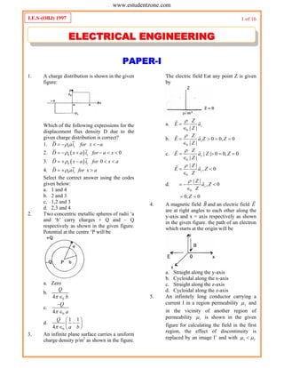
  • 1. 1 of 16 PAPER-I 1. A charge distribution is shown in the given figure: Which of the following expressions for the displacement flux density D due to the given charge distribution is correct? 1. 0 xD ai for x a    2.  0 0xD x a i for a x      3.  0 0xD x a i for x a     4. 0 xD ai for x a   Select the correct answer using the codes given below: a. 1 and 4 b. 2 and 3 c. 1,2 and 3 d. 2,3 and 4 2. Two concentric metallic spheres of radii ‘a and ‘b’ carry charges + Q and – Q respectively as shown in the given figure. Potential at the centre ‘P will be a. Zero b. 04 Q b  c. 04 Q a   d. 0 1 1 4 Q a b        3. An infinite plane surface carries a uniform charge density p/m2 as shown in the figure. The electric field Eat any point Z is given by a. 0 | | z Z E a Z      b. 0 0 0, 0 | | z Z E a Z Z Z         c. 0 | | 0 0, 0 | | z Z E a Z Z Z         d. 0 0 | | , 0 | | , 0 0, 0 z z Z E a Z Z Z a Z Z Z               4. A magnetic field B and an electric field E are at right angles to each other along the y-axis and x = axis respectively as shown in the given figure. the path of an electron which starts at the origin will be a. Straight along the y-axis b. Cycloidal along the x-axis c. Straight along the z-axis d. Cycloidal along the z-axis 5. An infinitely long conductor carrying a current I in a region permeability 1 and in the vicinity of another region of permeability 1 is shown in the given figure for calculating the field in the first region, the effect of discontinuity is replaced by an image I’ and with 1 2  I.E.S-(OBJ) 1997 EELLEECCTTRRIICCAALL EENNGGIINNEEEERRIINNGG www.estudentzone.comwww.estudentzone.com
  • 2. 2 of 16 which one of the following statements is correct in this regard? a. I and I’ have the same strength and direction b. I and I’ have opposite direction but the same strength c. 1 and I’ have the same direction but different strength d. I and I’ have opposite direction and different strength 6. The image of the dipole of moment P in the grounded sphere shown in the given figure is a. A dipole of moment P b. A dipole of moment PR/d c. A dipole of moment PR2 /d2 d. Not a dipole 7. If two concentric square loops A and B shown in the given figure carry equal currents in the same sense, then the magnetic field at ‘O due to the two loops A and B will be in the ratio a. 1: 2 b. 1 : 1 c. 2 :1 d. 2 : 1 8. Match List-I (Phenomena) with List-Il (Reasons) and select the correct answer using the codes given below the lists: List I A. Force on a unit north pole due to current B. Flux density intensity relation in a magnetic material C. Force of attraction between a current carrying conductor and a magnetic slab D. Identically zero magnetic field outside a coaxial cable List II 1. Magnetic Polarization 2. Maximization of magnetic lines of force 3. Work done along a closed path is equal to total current flow 4. Force between magnetic elements A B C D a. 3 1 2 4 b. 4 1 2 3 c. 3 2 1 4 d. 4 2 1 3 9. Two point charges Q and – Q are located on the surface of a sphere of radius R as shown in the figure. The average electric field in the volume of the sphere is a. Infinite b.  2 0 2 4 Q n R    c.  2 0 2 4 Q n R    d. Zero 10. A flat slab of, dielectric ( 5r  )is placed normal to a uniform field with a flux density D = 1 Coulomb/m2 . The slab is uniformly polarized. Polarization V in the slab (in Coulomb/m2 ) will be a. 0.8 b. 1.2 c. 4.0 d. 6.0 11. A parallel plate capacitor with air as dielectric is charged and then disconnected from the supply. The force between the plates is F. If the cap actor is now immersed in a liquid dielectric of dielectric constant e, then the force between the plates will be a. 2 F b. F c. F d. /F  12. Match List-I with List-II and select the correct answer using the codes given below the Lists: (Symbols have the usual meanings) www.estudentzone.comwww.estudentzone.com
  • 3. 3 of 16 List I A. Poisson’s equation B. Laplace’s equation C. Joule’s equation D. Helmholtz’s equation List II 1. 2 0  2. 2 2 0 0E K E   where 0 0 0K    3. 2 0      4. .j dP U E J dV   A B C D a. 2 1 4 3 b. 3 4 1 2 c. 3 1 4 2 d. 2 4 1 3 13. A circular loop has its radius increasing at a rate of 2m/s. The loop is placed perpendicular to a constant magnetic field of 0.1 Wb/m2 . When the radius of the loop is 2 m, the emf induced in the loop will be a. 0.8 V b. 0.4 V c. 0.2 V d. Zero 14. Kirchhoff’s current law for direct currents is implicit in the expression a. .V D   b. . 0J n ds   c. . 0V B   d. D H J t      15. A rectangular loop in the x-z plane bounded by the lines x = 0, x = a, z = 0 and z = b, is in a time-varying magnetic field given by 0 cos yB B t a Where B0 is a constant,  is the angular frequency and ay is the unit vector in the y– direction, the emf induced in the loop is given by a. 0 cosabB t b. 0 sinabB t  c. 0 sinB t  d. Zero 16. In a broadside array, the maximum radiation a. Occurs at 90° to the line of the array b. Occurs at 450 to the line of the array c. Occurs along the line of the array d. Could occurat any angle to the line of the array 17. At a certain frequency ‘f’ a uniform plane wave is found to have established a wavelength  in a good conductor. Of the source frequency is doubled, then the wavelength would change to a. 2  b. 2 c. 2 d. 4 18. Two loss-less transmission lines 1 and .2 shown in the given figure have each a characteristic impendence Z. Line 1 is charged to a voltage of V and line 2 to a voltage of 2 V. Then both of them are discharged through resistances Z as shown. If line 1 gets fully discharged in time T, then line 2 will fully discharged in time a. T/4 b. T/2 c. T d. 2T 19. As the temperature of a ‘p’ type semiconductor is gradually and continuously increased, the Fermi level will move a. Into the valence band b. Into the conduction band c. Towards the middle of the forbidden gap d. Into the region between the acceptor. level and the valence band 20. Which one of the following polarization mechanisms/ sets of mechanisms contribute (s) to the static dielectric constant of a homopolar neutral dielectric? a. Electronic b. Electronic and ionic c. Electronic, ionic and dipolar d. Electronic, and dipolar 21. Consider the following materials: 1. Pure silica 2. Bakelite 3. Hard rubber 4. Paraffin www.estudentzone.comwww.estudentzone.com
  • 4. 4 of 16 The correct sequence of the DECREASING order of loss angle (60 Hz) these dielectric materials is a. 1, 2, 3, 4 b. 1, 4, 3, 2 c. 4, 1, 2, 3 d. 4, 3, 1, 2 22. Which one of the following materials is piezoelectric? a. Pb2Au b. Ba Ti O3 c. Mg A12O4 d. Ni Fe2O4 23. The residual resistivity of metals a. Is essentially independent of temperature b. Increase linearly with increasing temperature c. Decrease linearly with increasing temperature d. Initially increases linearly with temperature and then remains constant. 24. Consider the following metals: 1. Zinc. 2. Gold. 3. Silver. 4. Copper. The correct sequence of the increasing order of their resistivities is a. 4, 3, 1, 2 b. 3, 4, 2, 1, c. 4, 3, 2, 1 d. 3, 4, 1, 2 25. Match List-I with List-II and select the correct answer: List I (Class of material) A. Ferromagnetio B. Superconductor C. Semiconductor D. Piezoelectric List II (Material) 1. YBa2 Cu2 O7 2. LiNbO3 3. Co 4. InGaAsP A B C D a. 3 1 2 4 b. 3 1 4 2 c. 1 3 2 4 d. 1 3 4 2 26. A type I superconductor maintained at a temperature T<Tc is subjected to a magnetic field H<Hc. The superconductor will exhibit a. Perfect diamagnetism b. Partial diamagnetism c. Perfect paramagnetism d. Partial paramagnetism 27. The magnetic susceptibility of a paramagnetic material is a. Less than zero b. Less than one but positive c. Greater than one d. Equal to zero 28. Magnetostriction is phenomenon whereby the magnetization of a ferromagnetic material leads to a change in a. Relative permeability b. Physical dimensions c. Spontaneous magnetization d. Magnetic susceptibility 29. Match List - I with List-Il and select the correct answer List I (Type of magnetic material) A. Ferromagnetic B. Anti-ferromagnetic C. Ferromagnetic List II (Orientation of individual dipole moments) 1.     2.     3.     4.     A B C a. 4 2 1 b. 1 2 4 c. 2 1 3 d. 4 2 3 30. Match List-I with List-LI and select the correct answer List I (Application) A. Power transformer B. Audio transformer C. Pulse transformer D. Welding transformer List II (Core material) 1. Si-Fe alloy 2. Permalloy 3. Ferrite 4. Supermalloy 5. Hypersil A B C D a. 1 2 4 5 b. 2 3 4 5 c. 1 2 3 4 d. 2 3 5 4 31. Two initially identical samples A and B of pure germanium are doped with donors to www.estudentzone.comwww.estudentzone.com
  • 5. 5 of 16 concentrations of l  1020 m-3 and 3 l020 m -3 respectively. If the hole concentration in A is 9 1012 m-3 , then the hole concentration in B at the same temperature will be a. 12 3 3 10 m  b. 12 3 7 10 m  c. 12 3 11 10 m  d. 12 3 27 10 m  32. Consider the following statements: Pure germanium and pure silicon are examples of 1. Direct band-gap semiconductors. 2. Indirect band-gap semiconductors. 3. Degenerate semiconductors. Of these statements a. 1 alone is correct b. 2 alone is correct c. 3 alone is correct d. 1 and 3 are correct 33. Consider the following statements: In a semiconductor, the measurement of Hall coefficient provides quantitative information on 1. Density of carriers. 2. Polarity of carriers. 3. Effective mass of the carriers. 4. Mobility of the carriers. Of these statements a. 1 and 2 are correct b. 2 and 3 are correct c. 1 and 3 are correct d. 1, 2, 3 and 4 are correct 34. Silicon carbide reinforced aluminum metal matrix- composites find application in a. The manufacture of transformer cores b. The manufacture of cutting tools. c. The manufacture of standard resistors d. Aerospace industry 35. GaAsLEDs emit radiation in the a. Ultra-violet region b. Violet-blue-green range of the visible region c. Visible region d. Infra-red region 36. A series RLC circuit, consisting of R = 10 ohms, XL = 20 ohms and Xc = 20 ohms is connected across an ac supply of 100 V (rms). The magnitude and phase angle (with reference to supply voltage) of the voltage across the inductive coil are respectively a. 100 V; 90° b. 100 V; 900 c. 200 V; – 90° d. 200 V; 90° 37. From a sinusoidal voltage source Vs of impedance s s sZ R jX  , power is drawn by a load L L LZ R jX  .The condition for maximum power in ZL is given in List – II for the constraints shown in List – I. Match List - I with List - II and select the correct answer using the codes given below the Lists: List I A. Xs = zero B. XL = zero C. RL fixed D. XL fixed List II 1. 2 2 2 L S sZ R X  2. L L sZ R jX  3. L s sZ R jX  4. L sZ R 5.   1/222 L S s L LZ R X X jX       A B C D a. 4 1 2 3 b. 2 3 4 5 c. 4 1 2 5 d. 1 3 4 5 38. For the networks shown in figures A and B to be duals, it is necessary that R, L’ and C are respectively equal to a. 1/R, C and L b. 1/R, I/L and 1/C c. 1/ R, 1/L and C d. R, L and C 39. The impedance Z (s) of the one-port network shown in the figure is given by www.estudentzone.comwww.estudentzone.com
  • 6. 6 of 16 a. 2 1 1 RL s s C LC s LC    b. 2 1 2 1 2 2 2 2 1 L R R C R R s s R LC R LC L s R C      c. 2 1 1 2 1 1 RL C s s R R LC L s R C     d. 2 2 1 2 1 1 1 1 L R C R R s s R LC R LC s R C      40. Which of the following statement (s) is/are true of the circuit shown in the given figure? 1. It is a first order circuit with steady- state values of 5 5 , 3 3 V V I A  2. It is a second order circuit with steady state values of V = 1 V; I =1 A 3. The network function V(s) /I(s) has one pole. 4. The network function V (s) /I(s) has two poles. Select the correct answer using the codes given below: a. 1 and 3 b. 2 and 4 c. 2 alone d. 1 alone 41. In addition to the condition that Y (s) is real when ‘s’ is real, for an admittance function Y (s) to be positive real, which of the following conditions are to be satisfied? 1.  Re 0 Re 0Y s for s  2.  Re 0 Re 0Y s for s  3.  | | | | | | / 2Arg Y s Arg s for Arg s   4.  | | | | | | / 2Arg Y s Arg s for Arg s   Select the correct answer using the codes given below: a. 1 and 3 are correct b. 1 and 4 are correct c. 2 and 3 are correct d. 2 and 4 are correct 42. The circuit shown in the given figure is in steady-state with, switch ‘S’ open. The switch is closed at t = 0. The values of  0cV  and  cV  will be respectively a. 2 V, 0 V b. 0V,2V c. 2V,2V d. 0V,0V 43. After closing the switch ‘S’ at t = 0, the current i(t) at any instant ‘t’ in the network shown in the given figure will be a. 100 10 10 t e b. 100 10 10 t e c. 100 10 10 t e  d. 100 10 10 t e  44. The pole-zero configuration of a network transfer function is shown in the given figure. The magnitude of the transfer function will a. Decrease with frequency b. Increase with frequency c. Initially increase and then decrease with frequency d. Be independent of frequency 45. Consider the following statements: 1. The two-port network shown below does NOT have an impedance matrix representation. 2. The following two-port network does NOT have an admittance matrix representation www.estudentzone.comwww.estudentzone.com
  • 7. 7 of 16 3. A two-port network is said to be reciprocal if it satisfies z12 = z21 Of these statements a. 1 and 2 are correct b. 1, 2 and 3 are correct c. 1 and 3 are correct d. None is correct 46. Match List - I with List - II for the two- port network shown in the given figure and select the correct answer. List I A. Z11 B. Z12 C. Z21 D. Z22 List II 1. R 2. R+L 3. R-Ls 4. R+Ls A B C D a. 1 2 1 4 b. 2 1 1 3 c. 1 1 1 4 d. 2 1 3 4 47. Consider the following statements: I : Any function in ‘s’ which can be expressed as a ratio of any two arbitrary polynomials in ‘scan be realized s a driving- point function of a passive network. II: Any function in ‘s’ which can be expressed as a ratio of two arbitrary polynomials in ‘s’, is a positive ,real function. Of these statements a. both I and II are true b. I is true but 11 is false c. both I and II are false d. I is false but II is true 48. Consider the following polynomials: 1. 4 3 2 7 17 17 6s s s s    2. 4 3 2 11 41 61 30s s s s    3. 4 3 2 2 3 2s s s s    Among these polynomials, those which are Hurwitz would include a. 1 and 3 b. 2 and 3 c. 1 and 2 d. 1,2 and 3 49. Match List-I with List-II and select the correct answer: List I (Function) A. Unit tamp B. Unit step C. Unit impulse D. Unit doublet List II (Laplace transform) 1. s 2. 1 3. 1/s 4. 1/s2 A B C D a. 4 3 2 1 b. 3 4 1 2 c. 4 3 1 2 d. 3 4 2 1 50. A system is represented by  2 4 dy y tu t dt   The ramp component in the forced response will be a. Tu (t) b. 2t u(t) c. 3t u(t) d. 4t u(t) 51. The Laplace transform of the function i (t) is:     2 0 4 1 4 5 s I s s s s s       its final value will be a. 4/5 b. 5/4 c. 4 d. 5 52. If the unit step response of a network is  1 t e   , then its unit impulse response will be a. t e    b. /t e    c. 1 t e    d.  1 t e     53. In the network shown in the given figure, if the voltage v at the time considered is 20 V, then dv/dt at that time will be www.estudentzone.comwww.estudentzone.com
  • 8. 8 of 16 a. 1 V/s b. 2 V/s c. -2 V/s d. zero 54. Which one of the following pairs of poles and responses is correctly matched? Poles Response a. b. c. d. 55. The impulse response of an R-L circuit is a a. Rising exponential function b. Decaying exponential function c. Step function d. Parabolic function 56. A pulse of unit amplitude and width ‘a’ is applied to a series RL circuit as shown in the figure. The current i (t) as ‘t’ tends to infinity will be a. Zero b. 1 A c. A value between zero and one depending upon the width of the pulse d. Infinite 57. The sinusoidal steady-state voltage gain of the network shown in the given figure will have magnitude equal to 0.707 at an angular frequency of a. zero b. RC rad/s c. 1/RC rad/s d. 1 rad/s 58. The phase angle of the current ‘I’ with respect to the voltage V1 in the circuit shown in the figure is: a. 0° b. +45° c. – 45° d. – 90° 59. A second order system is given by 2 2 12 100 0 d y dy y dt dt    The damped natural frequency in rad/sec is a. 100 b. 10 c. 44 d. 8 60. An alternator is delivering power to a balanced load at unity power factor. The phase angle between the line voltage and the line current is a. 90° b. 60° c. 30° d. 0° 61. Eoa EOb and Eoc are three phase voltages while Eab , Ebc and Eca are the line voltage of a balanced three-phase system having a- b-c phase sequence. In relation to Eoc Ebc would a. Lag by 30° b. Lead by 30° c. Have the same phase d. Have no definite phase relationship 62. For loop 1 of the network shown in the given figure, the correct loop equation is: www.estudentzone.comwww.estudentzone.com
  • 9. 9 of 16 a.           1 1 1 2 2 12 d v t Ri t L i t i t dt di M t dt       b.             1 1 1 2 2 2 12 23 d v t Ri t L i t i t dt di di M t M t dt dt        c.               2 1 2 1 2 3 2 2 12 23 122 did L i t i t L L t dt dt di di M M t M t dt dt        d.               2 1 2 1 2 3 1 1 12 12 232 did L i t i t L L t dt dt di di M t M M t dt dt          63. Consider the following statements: In the circuit shown in the figure, if the equivalent impedance between x-x is Zeq then 1. 2 5eqZ j  2. 2 3eqZ j  3. 1 2I I  4. 1 2I I Of these statements a. 1 alone is true b. 2 and 4 are correct c. 2 and 3 are correct d. 1 and 4 are correct 64. The residues at the pole of Y (s). of an R– C network are a. Real and negative b. Real and positive c. Complex with positive real part d. Complex with negative real part 65. Consider the following statements: In a measuring instrument, 1. Linearity is more important than sensitivity 2. High precision indicates high accuracy. 3. Accuracy cannot be better than resolution. Of these statements a. 1, 2, and 3 are correct b. 1, and 2 are correct c. 2 and 3 are correct d. 1 and 3 are correct 66. What voltage would a voltmeter with impedance 20,000  and range 0–1V show in the circuit given below? a. 82 mV b. 100 mV c. 118 mV d. 5V 67. Match List-I with List-II and select the correct answer: List I A. Cesium B. Manganin C. Standard voltage D. IEEE 488 List II 1. Standard resistance 2. Atomic clock 3. Instrument interface 4. Josephson Junction A B C D a. 2 1 3 4 b. 2 1 4 3 c. 1 2 3 4 d. 1 2 4 3 68. The limiting errors of measurement of power consumed by and the current passing through a resistance are ± 1.5% and ± 1% respectively: The limiting error of measurement of resistance will then be a. ± 0.5% b. ± 1.0% c. ± 2.5% d. ± 3.5% 69. Horizontal deflection in a CRO is due to E sin t while vertical deflection is due to E sin  t  with a positive . Consider the following patterns obtained in the CRO. www.estudentzone.comwww.estudentzone.com
  • 10. 10 of 16 The correct sequence of these patterns in increasing order of the value of  is: a. 3, 2, 5, 1, 4 b. 3, 2, 4, 5, 1 c. 2, 3,5, 1,4 d. 2,3,5,4, 1 70. Which of the following until axe present in a spectrum analyzer? 1. Mixer. 2. Saw-tooth generator. 3. Local oscillator. Select the correct answer using the codes given below: a. 1, 2 and 3 b. 1 and 2 c. 1 and 3 d. 2 and 3 71. For the voltmeter circuit shown in the given figure, the basic D’ Arsonval meter used has full-scale current of 1 mA and meter resistance (Rm ) of 100 ohms. The values of the series resistance R1 and R2 required for 10V range and 50 V range will be respectively a. 9.9k and 40 k b. 10 k and 50 k c. 20 k and 30 k d. 200 k and 250 k 72. Electronic voltmeter provides ore accurate readings in high resistance circuits as compared to a non-electronic voltmeter because of Its a. High V/ohm ratings b. High ohm/ratings c. High meter resistance d. Low resolution 73. A current transformer has a phase error of + 30.The phase angle between the primary and secondary currents is a. 30° b. 177° c. 180° d. 183° 74. Modem electronic multimeters measure resistance by a. Using a bridge circuit b. Using an electronic bridge compensator for nulling c. Forcing a constant current and measuring the voltage across the unknown resistor d. Applying a constant voltage and measuring the current through the unknown resistor 75. In the case of power measurement by two- wattmeter method in a balanced 3-phase system with a pure inductive load, a. Both the watt meters will indicate the same value but of opposite sign b. Both the watt meters will indicate zero c. Both the watt meters will indicate the same value and of the same sign d. One wattmeter will indicate zero and the other will indicate some non-zero value 76. Many modem capacitance meters measure capacitance by making the unknown capacity an element in a charge amplifier. A schematic f the same is given below. If the maximum permissible output voltage is limited to 1Vpeak’ due to slew rate constrainst, then the maximum Cx, with be a. 10 pF b. 100 pF c. 1000 pF d. 10 nF 77. A 230 V, 10 A, single-phase energy meter makes 90 revolutions in 3 minutes at half load rated voltage and unity pf. if the meter constant is 1800 revolution, kWh, then its error at half load will be a. 13.04% slow b. 13.04% fast c. 15% slow d. 15% fast 78. A strain gauge bridge measures the strain in a cantilever where the gauge is fixed. With strain , the gauge resistance increases from 110 to 110.520. If the www.estudentzone.comwww.estudentzone.com
  • 11. 11 of 16 gauge factor is 2.03, then the strain in the cantilever will be a. 3 2.06 10  b. 3 3.15 10  c. 3 3.81 10  d. 3 4.33 10  79. Consider the following statements: The causes of error in the measurement of temperature using a thermistor are 1. Self heating 2. Poor sensitivity. 3. Non-linear characteristics. Of these statements a. 1, 2 and 3 are correct b. 1 and 2 are correct c. 2 and 3 are correct d. 1 and 3 are correct 80. A piezoelectric transducer has the following parameter values: Crystal capacitance = 10-9 F Cable capacitance = 210-10 F Charge sensitivity = 410-6 Coulomb/cm. If the oscilloscope used for read-out has an input resistance of 1 M in parallel with C = 4  10-10 F, then the voltage sensitivity constant will be a. 2500 V/cm b. 3334 V/cm c. 4000 V/cm d. 4500 V/cm 81. For a thermocouple pair (A,B), the extension wires (C,P) a. Should be identical pair elements b. Should ‘have identical temperature - emf relationship c. Can be of any tewo dissimilar materials d. Should have very small temperature - emf sensitivity 82. A 7- bit successive approximation DVM will convert the analog input into digital output in a period of a. 7 clock pulses b. 8 clock pulses c. input signal amplitude 7 clock pulses full-scale output amplitude  d. input signal amplitude 8 clock pulses full-scale output amplitude  83. Match List-I with List-Il. and select the correct answer: List I A. Low pass filter B. High pass filter C. Band pass filter D. Band reject filter List II 1. 1 Ts Ts 2. 1 1 1 Ts Ts        3. 1 1 1 sT Ts Ts Ts         4. 1 1 Ts A B C D a. 1 4 3 2 b. 4 1 2 3 c. 1 4 2 3 d. 4 1 3 2 84. Data buffering means a. A buffer stock of data already stored in a computer unit b. An electronic circuit which is used to maintain the level of data c. That data are first collected in an external, unit and then processed into the computer d. Application of buffer (unity gain amplifier) at input interface to the computer 85. A circuit draws a current T’. When a single-phase ac voltage V is applied to it. If the power factor is cos then the dimensions of VI cos would be a. ML3 T2 b. ML2 T3 c. ML3 T3 d. ML2 T-3 86. Given: KKt = 99 ; s = j1 rad/s, the sensitivity of the closed-loop, system (shown in the given figure) to variation in parameter K is approximately a. 0.01 b. 0.1. c. 1.0 www.estudentzone.comwww.estudentzone.com
  • 12. 12 of 16 d. 10 87. The transfer function C/R of the system shown in the figure is: a.   1 2 2 1 1 2 21 G G H H G G H b.   1 2 1 1 2 21 G H H G G H c.   1 2 1 1 2 11 G H H G G H d.   1 1 2 1 2 21 G H H G G H 88. The Nyquist plot for a control system is shown in Figure I. The Bode plot for the same system will be as in a. b. c. d. 89. A unity feedback second order control system is characterized by     K G s s Js B   where J = moment of inertia, K= system gain B viscous damping coefficient. The transient response specification which is NOT affected by variation of system gain is the a. Peak overshoot b. Rise time c. Settling time d. Damped frequency of oscillations 90. The root-locus plot for an uncompensated unstable system is shown in the given figure. The system is to be compensated by a compensating zero, .The most desirable location of the compensating zero would be the point marked. a. A b. B c. C d. D. 91. The open-loop transfer function of a unity feedback control system is        30 1 G s H s s s s T    where T is a variable parameter. The closed-loop system will be stable for all values of a. T > 0 b. 0 < T < 3 c. T > 5 d. 3 < T < 5 92. The Nyquist plot of the open-loop transfer function G (s) H(s) is shown in the given figure. It indicates that www.estudentzone.comwww.estudentzone.com
  • 13. 13 of 16 a. The open-loop system is unstable but the closed-loop system is stable b. Both open-loop and closed-loop systems are unstable c. Open-loop system is stable but closed- loop system is unstable d. Both open-loop and closed-loop systems are stable 93. In the control system shown in the given figure, the controller which can give zero steady-state error to a ramp input. with K = 9 is a. Proportional type b. Integral type c. Derivative type d. Proportional plus derivative type 94. The garn cross-over frequency and band- width of a control system are cu and bu respectively. A phase-lag network is employed for compensating the system. If the gain cross-over frequency and bandwidth of the compensated system are cc and bc respectively, then a. ;cc cu bc bu     b. ;cc cu bc bu     c. ;cc cu bc bu     d. ;cc cu bc bu     95. The transfer function of a certain system is     4 3 2 1 5 7 6 3 Y s U s s s s s      The A, B matrix pair of the equivalent state-space model will be a. 0 1 0 0 0 0 0 1 0 0 0 0 0 1 0 3 6 7 5 1                            b. 0 1 0 0 0 0 0 1 0 0 0 0 0 1 0 3 5 6 7 1                            c. 0 1 0 0 1 0 0 1 0 0 0 0 0 1 0 5 7 6 3 0                            d. 1 0 0 0 0 0 0 0 0 0 0 0 1 0 0 3 6 7 5 1                            96. A liner system is described by the state equations 1 1 2 2 1 0 0 1 1 1 x x r x x                       C = x2 where r and c are the input and output reactively. The transfer function is: a. 1/ (s+1) b. 1/(5+1)2 c. 1/ (s-1) d. 1/ (s-1)2 97. The state equation of a dynamic system is given by    X t AX t 1 1 0 0 0 0 1 1 0 0 0 0 1 0 0 0 0 6 3 4 0 0 0 4 3 A                  The eigenvalues of the system would be a. Real non-repeated only b. Real non-repeated and complex c. Real repeated d. Real repeated and complex 98. A simple electric water heater is shown in the given figure. The system can be modelled by a. A first order differential equation b. A second order differential equation c. A third order differential equation d. An algebraic equation www.estudentzone.comwww.estudentzone.com
  • 14. 14 of 16 99. Match List-I with List-Il and select the correct answer List I (Properties of frictional force) A. B. C. List II (Frictional force) 1. Coulomb friction 2. Viscous friction 3. Static friction A B C a. 1 2 3 b. 2 1 3 c. 3 2 1 d. 2 3 1 100. Laplace transform of the output response of a liner system is the system transfer function when the input is a. A step signal b. A ramp signal c. An impulse signal d. A sinusoidal signal 101. Match List-I with list-II and select the correct answer: List I A. Hydraulic actuator B. Flapper valve C. Potentiometer error detector D. Dumb-bell rotor List II 1. Linear device 2. A.C. servo systems 3. Large power to weight ratio 4. Pneumatic systems A B C D a. 4 3 2 1 b. 3 4 2 1 c. 3 4 1 2 d. 4 3 1 2 102. Which of the following statements regarding an ac servo system employing a synchro error detector are correct? 1. Sensitivity of the error detector is measured in volts/degree. 2. The transfer function of the synchro error detector is r c E   where E = error voltage, r and c are reference and controlled shaft positions. 3. Sensitivity of the error detector has the same sign at the two null positions. a. 1, 2 and 3 b. 1 and 2 c. 2 and 3 d. 1 and 3 103. Four speed-torque curves (labelled I, II, III and IV) are shown in the given figure. That of an ac servomotor will be as in the curve labelled a. I b. II c. III d. IV 104. A non-linear control system is described by the equation 2 2 sin 0 d x x dt   The type of singularity at x  and dx dt = 0 is: a. Centre b. Stable focus c. Saddle point d. Stable node 105. Which one of the following pairs of phase- plane diagram and types of singularities is NOT correctly matched? Phase-plane diagram Singularity a. b. www.estudentzone.comwww.estudentzone.com
  • 15. 15 of 16 c. d. 106. Consider the following state equations for a discrete system:          1 1 2 2 1 0 1 12 1 1 1 1 4 4 x k x k u k x k x k                                     1 2 1 1 4 x k y k u k x k         The system given above is a. Controllable and observable b. Uncontrollable and unobservable c. Uncontrollable and observable d. Controllable and unobservable 107. Which one of the following systems is open-loop? a. The respiratory system of man b. A system for controlling the movement of the slide of a copying milling machine c. A thermostatic control d. Traffic light control 108. Assertion A: In general, circulation of the magnetic field intensity is zero. Reason R: Vector source of circulation is the current density. a. Both A and R are true and R is the correct explanation of A b. Both A and R are true but R is NOT a correct explanation of A c. A is true but R is false d. A is false but R is true 109. Assertion A: In some semiconductors, the Hall coefficient is positive. Reason R: In these semiconductors, the mobility of holes is greater than that of electrons. a. Both A and R are true and R is the correct explanation of A b. Both A and R are true but R is NOT a correct explanation of A c. A is true but R is false d. A is false but R is true 110. Assertion A: Intrinsic germanium does not show n-type behavior. Reason R: In intrinsic germanium, the number of electrons is less than the number of holes. a. Both A and R are true and R is the correct explanation of A b. Both A and R are true but R is NOT a correct explanation of A c. A is true but R is false d. A is false but R is true 111. Assertion A: Quartz crystal is preferred over Rochelle salt crystal for commercial piezoelectric applications. Reason R: Rochelle salt is mechanically weaker. a. Both A and R are true and R is the correct explanation of A b. Both A and R are true but R is NOT a correct explanation of A c. A is true but R is false d. A is false but R is true 112. A voltmeter with a resistance of 10 k is connected with two other 10k resistors across a 200 V 3 - phase mains, as shown in the figure: Assertion A: The voltmeter reading will be 115 V. Reason R: The connections are similar to Scott connection. a. Both A and R are true and R is the correct explanation of A b. Both A and R are true but R is NOT a correct explanation of A c. A is true but R is false d. A is false but R is true 113. Assertion A: The bridge shown in the figure is balanced by first adjusting R1 for inductive balance and then adjusting R3 for www.estudentzone.comwww.estudentzone.com
  • 16. 16 of 16 resistive balance; and this is repeated till balance is achieved. Reason R: For medium-Q coils, the resistance effect is not pronounced and balance ia reached after a few adjustments. a. Both A and R are true and R is the correct explanation of A b. Both A and R are true but R is NOT a correct explanation of A c. A is true but R is false d. A is false but R is true 114. Assertion A: Electrometers are used at the output stage of electrode pH meters. Reason R: In electrode type pH meters, the potential is measured using reference and measuring electrodes. a. Both A and R are true and R is the correct explanation of A b. Both A and R are true but R is NOT a correct explanation of A c. A is true but R is false d. A is false but R is true 115. Assertion A: The frequency response shown in the given figure is that of a vibration galvanometer. Reason R: A vibration galvanometer is the most suitable detector in ac potentiometer method of measurement. a. Both A and R are true and R is the correct explanation of A b. Both A and R are true but R is NOT a correct explanation of A c. A is true but R is false d. A is false but R is true 116. Assertion A: The solution of 1 3 2 digit voltmeter is 0.001. Reason R: Addition of 1 2 digit to a digital voltmeter increases the range of the meter. a. Both A and R are true and R is the correct explanation of A b. Both A and R are true but R is NOT a correct explanation of A c. A is true but R is false d. A is false but R is true 117. Assertion A: Section AB on the negative real axis in the given figure lies on the root-locus. Reason R: All the points in between A and B have two poles to the right of the points. a. Both A and R are true and R is the correct explanation of A b. Both A and R are true but R is NOT a correct explanation of A c. A is true but R is false d. A is false but R is true 118. Assertion A: Feedback control systems are often compensated by phase lead/phase-lag networks Reason R: Phase-lead/phase-lag networks are easily realizable and obtainable. a. Both A and R are true and R is the correct explanation of A b. Both A and R are true but R is NOT a correct explanation of A c. A is true but R is false d. A is false but R is true 119. Assertion A: A discrete data system having the characteristic equation 2 1.5 1 0Z Z   is unstable. Reason R: The negative coefficients of the characteristic equation in the z-plane represent an unstable discrete system. a. Both A and R are true and R is the correct explanation of A b. Both A and R are true but R is NOT a correct explanation of A c. A is true but R is false d. A is false but R is true 120. Assertion A: A dipole placed in a uniform field experiences a torque tending to align the dipole axis with the field. Reason R: A dipole placed in a uniform field does not experience a translational force. a. Both A and R are true and R is the correct explanation of A b. Both A and R are true but R is NOT a correct explanation of A c. A is true but R is false d. A is false but R is true www.estudentzone.comwww.estudentzone.com