Instruction manual | Falcon T50 | Optics Trade
•
0 likes•186 views

https://www.optics-trade.eu/en/falcon-t50-10-50x60.html

Recommended
Recommended
More Related Content
What's hot
What's hot (20)
Similar to Instruction manual | Falcon T50 | Optics Trade
Similar to Instruction manual | Falcon T50 | Optics Trade (20)
More from Optics-Trade
More from Optics-Trade (20)
Recently uploaded
Recently uploaded (20)
Instruction manual | Falcon T50 | Optics Trade
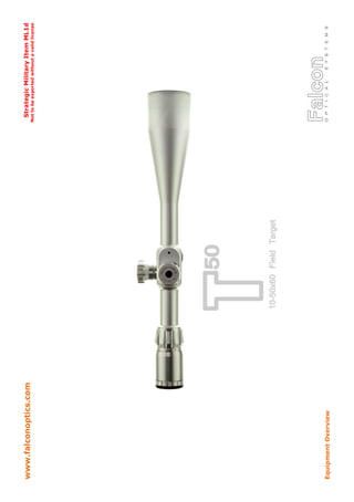
- 2. T50 Specification Ultra high power sporting scope, designed for precision target competition at <100yards range. Optical design engineered to give accurate range-finding capability to within 1.5yards at 50yards range. T50 10-50x60 MAGNIFICATION RANGE 10-50 FIELD OF VIEW @ 100y 9.6 - 2.2 ft EYE RELIEF @50x 78mm / 3.1in TOTAL ELEVATION ADJUSTMENT RANGE 30.0MOA ADJUSTMENT VALUE PER CLICK 1/8MOA ADJUSTMENT PER TURN 7.5MOA RETICLE CHOICES Mildot (Standard Mildot 10x) RETICLE INSTALL Second Focal TOTAL LENGTH 440mm / 17.32in WEIGHT 995g / 35.1oz TUBE DIAMETER 30mm / 1.18in CONSTRUCTION 1 Piece Tube/Saddle/Objective OBJECTIVE LENS DIAMETER 60mm / 2.36in OUTER OBJECTIVE DIAMETER 66mm / 2.60in OUTER OCULAR DIAMETER 44mm / 1.73in ADDITIONAL SUNSHADES 2 Supplied FLIP UP LENS COVERS Yes, Supplied CONFIGURATIONS AND ORDER CODES T50FT - Standard Mil Dot Reticle with 1/8MOA Adjustment MT50FT - Standard Mil Dot Reticle with 0.05MRAD Adjustment T50LM - Standard Mil Dot Reticle with 1/8MOA Adjustment T50LM(S) - Standard Mil Dot Reticle with 1/8MOA Adjustment (Silver) T50 - 10-50x60 Field Target Riflescope
- 3. 125mm side wheel x 1 Custom elevation turret x 1 Flip up lens covers x 1 set Lens cleaning cloth x 1 Hex key for windage/elevation turret caps x 1 Hex key for 125mm side wheel x 1 Side wheel and turret cap yardage labels x 1 set Threaded sunshade x 2 Objective thread protector (already installed) x 1 T50 Sticker x 1 What's Included? 1 - Objective end. Contains the 60mm objective lens assembly and objective lens hood. Both the sunshade and objective protector thread into the objective hood. 2 - Ocular end. Contains the ocular lens assembly. This is threaded for ad- justment, sometimes referred to diopter correction or ‘European style fast focus eyepiece’. 3 - Eyepiece section. This houses the second focal plane reticle. 4 - Magnification ring. This rotates to adjust the magnification setting be- tween 10 and 50. 5 - Side parallax adjustment turret. Sometimes referred to as ’side focus’ or ’SF’. This turret is used to dial out parallax, it adjusts back and forth. 6 - Elevation and Windage turrets. These are used to adjust the position of the reticle and ’zero in’. 7 - Saddle section. This houses the elevation, windage and side parallax turrets. To the front and rear of the saddle section is the 30mm main tube. 8 - Standard Mil Dot Reticle. A millradian based reticle (MRAD). Basics
- 4. Fast Focus Ocular Lens / Diopter Adjustment - It’s important that the reticle appears sharp and is correctly set to your eye. - Use the fast focus eyepiece to adjust the sharpness of the reticle to suit your eyesight, by pointing the scope at a fea- tureless bright area such as a wall or open sky. - Turn the fast focus eyepiece clockwise and anticlockwise until the reticle appears as sharp and defined as possible. - If the above is not carried out correctly then parallax error may become a problem. Do this first, before the scope is even mounted. - Once the eyepiece is set then don’t adjust it. Mounting the riflescope CAUTION : Ensure the firearm is not loaded when mounting the riflescope. - All Falcon models are built around a 30mm tube/saddle section of one-piece construction. - Always use good quality mounts/rings. Poor quality mounts/rings may damage your scope and will almost certainly hinder performance. - T50 has a low adjustment range of around 30MOA total due to the 5x magnification ratio and high top end magnification. As a result we recommend the use of adjustable mounts/rings and or a tapered rail/base in conjunction with this scope. - Be careful not to crush the scope tube by over tightening the mounts/rings. Refer to literature supplied with the mounts/rings to ensure the correct torque settings are used on both the top screws and base screws. Each set of mounts/rings and supplied screws should be built to a specific tolerance that will determine the correct torque setting. Windage / Elevation Turret Adjustment - T50 has an adjustment value of 1/8MOA per click. This equates to just over 1/16” @ 50 Yards and 1/8” @ 100 Yards. The total elevation range is around 30MOA, this translates to 4 full turns of the elevation turret. - T50 will be preset to mechanical centre (midway point of adjustment range) out of the box. Try and keep both the windage and elevation turrets as close to mechanical centre as possible when zeroing. Optical standard and adjustment consistency may suffer at the extremes of any scopes adjustment range. This is why we recommend the use of a tapered base or adjustable mounts/rings to aid zeroing and ensure T50 gives the best possible performance. - You will feel a positive resistance ‘stop’ once the scope reaches the extreme of its elevation or windage adjustment. Don't be tempted to force the turret any further as this will damage the mechanism. - T50 features elevation and windage turret caps that are secured using a single top mounted holding screw The turret caps can be repositioned as required, normally to display ‘0’. To do this then slacken the holding screw using the key provided in the box. Then disengage the turret cap by easing it off the internal shaft. A little upward force may be re- quired to break the O-ring seal. Reposition the turret cap as desired, applying downward force to re-engage the turret with the spline and make the O-ring seal. Finally, retighten the holding screw to secure. - Use exactly the same method to install the supplied custom elevation turret. This additional turret has a bigger surface area to install the supplied Rangesports sticker set. Guidance For Use
- 5. Side Parallax Adjustment - T50 has been designed to enable accurate range finding capability out to 55 yards via the use of the side parallax turret. Careful use of the side parallax turret will appear to bring targets in and out of focus. - Generally speaking, the higher the magnification setting that is used, then the easier it will be to determine if the target and image is in or out of focus. - To enable greater range finding precision a 125mm additional side wheel is included with the T50. The collar of the 125mm wheel should simply push-fit over the side parallax turret. Once in place then gently tighten the 3 grub screws with the hex key provided. At this point, be sure to align the 125mm wheel with a reference point on the side parallax turret. - Range finding as described above will be a trial and error process. The 125mm wheel allows you to indicate your own distance increments once the desired ranges have been marked and verified. - Once this process of marking the wheel is done then please use the yardage increment labels provided to indicate the desired distances and complete the set-up. - If you decide to remove the 125mm wheel after this point then you must ensure the placement is precise when re- installing. The 125mm wheel must align with the original reference point on the side parallax turret. - During development and testing T50 has shown impressive thermal stability and thus minimal change in its range find- ing performance through the seasons. A separate summer and winter wheel setup might be beneficial although there is no hard and fast rule to follow in terms of temperature and its effects on range finding. Magnification Adjustment - T50 has a 5x magnification optical system, adjustable from 10-50x power. - To adjust the magnification simply rotate the ring by hand to the desired setting. - CAUTION : Do not tamper with the hex screw on the magnification ring, this does not adjust the ring tension. - The zeroed point of impact (POI) should remain unchanged across the entire magnification range, but additional aim points that may be used for holdover/under and windage will change. This is because the reticle is installed in the second focal plane (SFP). Mil Dot Reticle - T50 uses a standard Mil Dot reticle installed in the second focal plane, calibrated for millradian accuracy at 10x magnifi- cation. - The distance from the centre of dot to dot = 1.0MRAD - 1.0MRAD = 10cm @ 100m. 1.0MRAD = 3.6” @ 100y. 1.0MRAD = 3.438MOA - A = 1.0MRAD - B = 5.0MRAD - C = 0.4MRAD - Reticle line thickness = 0.06MRAD - Dot size = 0.22MRAD Diagram not to scale Guidance For Use
- 6. Guidance For Use Sunshade - T50 is supplied with 2 additional sunshades. When shooting in low winter sun, or very sunny days then you may find this to be useful. To install then simply remove the thread protector from the objective lens hood and replace with the sun- shade. The thread protector can then be added to the end of the sunshade if you wish. 125mm side wheel - For installation instructions please consult the ‘Side Parallax Adjustment’ section on the previous page. Yardage labels for turret caps and side wheel - For installation instructions please consult the labels packaging. Care and Maintenance - With the exception of repositioning the turret caps along with adding/removing sunshades and the thread protector then do not attempt to disassemble the scope. - Do not tamper with the hex screw on the magnification ring. Nor the nitrogen port screw on the base of the saddle which should be covered by a sticker. - Do not attempt to ‘re-parallax’ the scope by adjusting the position of the front lens assembly. In doing so you run the risk nitrogen loss and moisture ingress over time. - When the scope is not in use then we recommend that the 125mm side wheel is removed. If the scope was to fall then the wheel provides extra leverage to damage the side parallax turret. - You will feel a positive stop at the end of the travel ranges for the windage and elevation turrets, focus eyepiece and side parallax adjustment turret. Don’t be tempted to apply more force once you reach the stop. - When mounting the scope always be sure to check the torque settings for the mounts/rings that you plan to use. - The external lens surfaces can we wiped clean with the lens cloth provided. Remove any noticeable particles of dirt or sand in advance using a lens blower or a very soft brush. Take care in doing this to ensure the outer lens coatings do not get scratched. - Store the scope in a moisture free environment. - Don’t leave the scope in direct sunlight whereby the suns rays can enter either the objective or ocular ends. - Avoid storing the scope in areas that will reach very high temperatures. - CAUTION : Never use the scope to look at the sun!
- 7. Troubleshooting Can’t zero the scope, running out of windage and/or elevation adjustment - Rule out common alignment issues such as: barrel alignment and shift, barrel threaded at an angle, rail/receiver install, rail alignment, mount/rings install and alignment. - It might be that a tapered (inclined) rail is necessary in order to gain the desired elevation adjustment. - Adjustable mount/rings are also available, often these are windage and elevation adjustable. I’m seeing a dark shadow around the image edges, it seems to disappear at higher magnification but return at lower magnification - Windage and/or elevation turrets are dialled to far from mechanical centre. Return them closer to mechanical centre and the shadow will ease. - If your having to dial in that much windage/elevation in order to zero then we would recommend the use of a ta- pered rail or adjustable mounts/rings. My group size has opened up after shooting well in the past / Shift in point of impact - Recent change of ammunition? - Pellet/round clipping silencer/moderator? - Inconsistent head position? - Barrel shift? - Warped stock fouling barrel? - Change to focus eyepiece setting? - Scope appear to be shifting in the mount/rings? - Play/movement between the rings/rail/receiver? - Parallax being dialled out correctly? - Windage and/or elevation turrets are dialled to far from mechanical centre? Loss of tension on erector spring. Return closer to mechanical centre. Side parallax turret difficult to turn after mounting the scope or suddenly develops stiffness / Difficulty in dialling out parallax / Inconsistent range finding - Torque setting on the mount/ring screws could be too high. Drop the level of torque applied with particular concern to the front mount/ring. - Mount/ring could just be out of tolerance, applying uneven force to the tube and putting strain on the side parallax mechanism. - Try shifting the front mount/ring further forward, closer to the objective end. - If after removing the mount/rings altogether and the side parallax turret still feels stiff to rotate then contact Falcon Optics Optical standard suddenly seems noticeably poorer - Recent changes to zero and elevation/windage setting? Optical standard may suffer at the extremes of any scopes adjustment range. - Check for changes to focus eyepiece setting and that parallax is being correctly dialled out. - Head alignment consistent? - Shooting in low sun? Use the sunshade. - Check for any obstructions on exterior lens surfaces such as dust, dirt and condensation.
- 8. - Mirage on a hot day? Only way to combat this is to drop the magnification setting. - Any debris visible within the scope? Any signs of moisture ingress? If so then contact Falcon Optics. Scope does not seem to track and shift the point of impact as it should - If you dialling for elevation then check the position of the windage turret. If the windage turret is to far from me- chanical centre then this will impact on the consistency of the elevation adjustment and vice versa. In this scenario it will even limit the total elevation adjustment range available to you. - If you are dialling adjustment and the scope is reaching the end of its adjustment range then you may notice a drop- off in the accuracy of each click. Windage and Elevation turrets feel mushy and don't give much of a ‘click’ - Remove the offending turret cap and you will notice an O-ring on the lower portion of the turret internal. Its this O- ring that is providing the friction and hindering the feel and ‘click’. You can try re-lubricating the O-ring with a silicone based grease or spray and you should notice an improvement. Warranty Your new Rifle Scope has a 10 year warranty that covers defects in materials and or workmanship. The warranty does not cover instances of abuse, user error, improper use or should the scope be dismantled by any- one other than Falcon Optics or its representatives. The warranty is limited to the original person that purchased the scope and is non transferable. The original proof of purchase is required in the event of a warranty claim. No guarantee can be given if a dated proof of purchase can not be provided. If you are concerned that the Rifle Scope has developed a fault or defect then either contact Falcon Optics directly or contact the Falcon Optics representative from which the scope was purchased. In cases where the Rifle Scope does need to be returned then details of where to return to will be given at the time of contact. Do not send the scope without contacting either Falcon Optics or its representative in advance and obtaining return authorisation. The original proof of purchase must be sent with the scope being returned, along with full name, address and contact details. A letter with as much information on the fault as possible should also be included. The scope should be well packaged, pre-paid and fully insured against damage or loss. After returning, the unit will be inspected then repaired or replaced at the option of the guarantor. For more details on the returns procedure please consult the resources section of the Falcon Optics website - www.falconoptics.com or contact Falcon Optics directly. The returns procedure will differ if you are outside of the United Kingdom. The terms and conditions above set out the minimum that we will provide and are in addition to your statutory rights. Export Notice This Rifle Scope is classified as a Strategic Military Item ML1d. It can’t leave the United Kingdom without a valid ex- port license. Do not attempt to export this scope from the UK without written permission from the Export Control Organisation of BIS (Department for Business, Innovation and Skills). If you are outside the UK then similar rules may apply, consult with your Export Control equivalent before taking/ sending the scope abroad. Troubleshooting continued... www.falconoptics.com