1. Paleoflood discharge analysis of late Wisconsinan jökulhlaups, Mentasta Pass valley, northeastern Alaska Range, using modern
engineering theory
1 Mining and Geological Engineering Department, University of Alaska Fairbanks, PO Box 755800, Fairbanks, AK 99775-5800;
2 Reger’s Geologic Consulting, PO Box 3326, Soldotna, AK 99669-3326;
3 Alaska Division of Geological & Geophysical Surveys, 3354 College Rd., Fairbanks, AK 99709
Southerland, L. E. 1, Reger, R. D. 2, Hubbard, T. D. 3, Darrow, M. M.1
ABSTRACT
Physiographic and stratigraphic evidence indicates that during flood-surge events,
meltwater from Glacial Lake Atna periodically poured through the lower Slana River
valley and entered the upper Tok River during the last major (Donnelly) glaciation.
Paleoflood levels were interpreted on aerial photographs and IfSAR (Interferometric
Synthetic Aperture Radar) imagery. Using a digital elevation model, ArcGIS and
Grapher-generated topographic profiles, engineering parameters were derived to
estimate paleoflood discharges and open-channel flow velocities for flood elevations
ranging from 673 to 761 m (relative to North American Vertical Datum of 1988), using
Manning’s equation. Manning’s equation calculations indicate paleoflood discharge
and open-channel velocity values were between ~4.3-7.5 x 10⁶ m3/s and ~32-37 m/s,
respectively. Froude numbers were calculated, and results indicate values ranging from
1.15 and 1.18, classifying the flow as supercritical.
Open-Channel Flow Velocity Flood Discharge Froude Numbers
1a. Manning’s equation (v)
Formula: v = R2/3S1/2
n
Parameters :
v = open-channel flow velocity
R = hydraulic radius
S = channel slope
n = Manning’s roughness coefficient
2a. Discharge equation (Q)
Formula: Q = Av
Parameters:
Q = discharge
A = cross-sectional area of channel
v = open-channel flow velocity
3a. Froude’s equation (Fr)
Formula: Fr = v___
(gD)1/2
Parameters:
Fr = Froude number
v = open-channel flow velocity
g = acceleration of gravity
D = depth of flow
Manning’s equation describes velocity of water through a channel at
a given cross-sectional location along that channel. Slope, cross-
sectional length, and area must be determined.
Volumetric flow, or discharge, characterizes the flow as steady or
unsteady. Discharge is the amount of water traveling past a certain
point in the channel.
Froude numbers serve as a classification system of flow magnitude.
Classification can be subcritical (<1), critical (~1), or supercritical (>1).
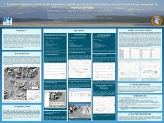
Topographic Cross
Sections
To determine open-channel flow velocity,
discharge, and Froude numbers, cross-sectional
profiles were interpolated from IfSAR digital
elevation models provided for the study area (See
Figure 8 as an example).
1b. Hydraulic Radius (R)
Hydraulic radius along the profile line describes the
radius of the channel in which flow occurs and is
calculated by the division of cross-sectional area (A)
and wetted perimeter (P) (See Figure 2 for an
example).
1c. Channel Slope (S)
Channel slope was derived from the Add Z
Information tool provided in ArcMap, inter-
polating and averaging slope values along lines in
the center of the flood channel (See Figure 3).
1d. Manning’s Roughness
Coefficient (n)
Manning’s n is determined from an engineering
table of values describing channel vegetation,
geology, and other possible obstructions
(Henderson, 1966).
2b. Cross-Sectional Area (A)
Flood height levels were determined using topo-
graphic indicators and Grapher’s Calculate Area
function was utilized to calculate the area below the
flood level and above the profile line (See Figure 4).
2c. Open-Channel Flow Velocity (v)
As determined in the previous calculation process,
open-channel flow velocity is essential for discharge
output (See Figure 5 for example calculations and
Figure 6 for 3 cross sections).
3b. Depth of flow (D)
The height of the flood channel is the difference
between the determined flood level and the
bottom-most elevation point along the channel
profile (See Figure 7).
Figure 8. Profile E-E’ east of Mentasta Pass, perpendicular to flood
channel.
INTRODUCTION
METHODS RESULTS & DISCUSSION
FUTURE RESEARCH
REFERENCES
BACKGROUND
The study area of the Glacial Lake Atna jokulhlaup floods is south of Tok, Alaska, east
of Mentasta Pass and Station Creek valley. Paleoflood discharge analysis was conducted
on one of the main flood pathways (Figure 1). Glacial Lake Atna was the source of
flooding that removed existing glacial ice and eventually poured into the Station Creek
valley and upper Tanana River drainage (Reger and others, in prep.). Flood scouring
distribution of deposits, and mineral lake moraines are apparent on high-resolution
IfSAR imagery, and deposits identified in the field are evidence that the jokulhlaups
were large-scale events.
Open-channel flow analysis includes the calculation and derivation of open-channel
flow, volumetric discharge, and classification of flow using Froude numbers
(Henderson, 1966). Our analysis shows the calculation parameters were derived using
ArcGIS and Grapher 10 to output theoretical values for the glacial outburst flood events
in the Mentasta Pass and Station Creek valley. IfSAR digital elevation models
(Geographic Information Network of Alaska, 2012) were used to determine parameters
such as hydraulic radius, slope, cross-sectional area, and depth of flow along cross
sectional profile lines.
When comparing the cross-sectional profile results, assumptions were made about conditions at the
time of jokulhlaup flooding through Station Creek valley. For preliminary calculations we assumed
the valley was ice-free and flood levels represent maximum values (see Table 1). Based on open-
channel flow theory, the calculations indicate a maximum cross-sectional velocity of 37.3 m/s, a
peak discharge of 6.6 x 10⁶ m3/s, and a maximum Froude value of 1.21 (supercritical or rapid flow).
Flood values are maximums and the valley likely contained ice during flooding, resulting in flood
volumes less than those calculated. Multiple flood levels can be identified using topographic
profiles. In profile E, flood levels changed from a maximum height of 756 m to a low of 680 m from
the bottom of the channel, decreasing the flood velocity from 37.3 m/s to 12.4 m/s (Figure 9). Profile
F changed from a maximum flood level of 761 m to a low of 673 m, decreasing flood velocities from
37.4 m/s to 11.7 m/s (Figure 10). Higher flood levels most likely overestimate the actual velocity at
which the flood waters were moving. Consideration must be given to the thickness of ice remaining
in the valley bottom during flooding and the impact this had on flood flow.
Table 1. Open channel flow analysis results of multiple interpolated profiles in Station Creek Valley.
IfSAR (Interferometric Synthetic Aperture Radar), with a vertical accuracy of 2 m, was used for
interpolation in this study area. With the availability of higher resolution imagery, such as LiDAR
with 1 m vertical accuracy, more precise calculations can be performed. In addition to better imagery,
determination of actual flood levels from field work in the study area corresponding to the
topographic profiles would help to confirm flood levels for more precise calculations.
Figure 6. 3D view of the Station Creek valley on IfSAR hillshade
image.
Figure 1. IfSAR hillshade showing study area location and jokulhlaup paleoflow direction.
Figure 9. Profile E showing the potential ice
depth that could have affected flow rate.
Figure 10. Profile F showing the potential ice
depth that could have affected flow rate.
Davis, C.V., and Sorensen, K.E., 1969, Handbook of Applied Hydraulics, 3rd ed. :New York,
McGraw-Hill Book Company, p. 5-1 – 5-9.
Geographic Information Network of Alaska, 2012, http://ifsar.gina.alaska.edu/
Henderson, F.M., 1966, Open Channel Flow. The Macmillan Company. New York. p. 12-103.
Kehew, A.E., 2006, Geology for Engineers & Environmental Scientists, 3rd ed.: Upper Saddle River,
New Jersey. Prentice Hall. p. 554-557.
Merritt, F.S., 1968, Standard Handbook for Civil Engineers: New York, McGraw-Hill Book Company,
p. 21-47 – 21-48.
Reger, R.D., Hubbard, T.D., and Koehler, R.D., Surficial geology and geohazards in the Alaska
Highway corridor, Alaska. Alaska Division of Geological and Geophysical Surveys. In
preparation.
Figure 2. Hydraulic radius for profile line E-E’ indicated in red.
Figure 4. Cross sectional area of profile F-F’.
Figure 7. Maximum and minimum points used to calculate depth.
ACKNOWLEDGEMENTS
I would like to thank my co-authors for their contribution and constructive suggestions during the
creation of this poster. I would also like to thank the staff of Alaska Division of Geological &
Geophysical Surveys, the University of Alaska Fairbanks, and the Geological Society of America for
giving me this opportunity and resources to complete this project.
Figure 3. ArcMap-derived slope profile along the center of Station
Creek valley.
Figure 5. Open-channel flow velocity calculations in Excel.
Profiles
cross sectional average velocity (V)
(m/s) Discharge (Q) = V*A (m^3/s) Froude number
Profile E (756 m) 37.3 6.6 x 10⁶ 1.21
Profile E (739 m) 32.2 4.3 x 10⁶ 1.15
Profile E (727 m) 28.3 2.3 x 10⁶ 1.10
Profile E (680 m) 12.4 2.4 x 10⁵ 0.86
Profile F (761 m) 37.4 7.5 x 10⁶ 1.18
Profile F (742 m) 31.0 4.5 x 10⁶ 1.08
Profile F (710 m) 23.7 1.7 x 10⁶ 1.05
Profile F (673 m) 11.7 1.6 x 10⁵ 0.97