1. 21 G 72 Overhaul and ‘trendable’ data gathering.
21 G 72 Overhaul and ‘trendable’ data gathering.
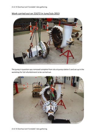
Work carried out on 21G72 in June/July 2013
The pump in question was removed complete from situ at pump station 5 and set up in the
workshop for full refurbishment to be carried out.
2. 21 G 72 Overhaul and ‘trendable’ data gathering.
21 G 72 Overhaul and ‘trendable’ data gathering.
To improve the knowledge of ‘ageing plant’ condition monitoring, the pump was completely
stripped to assess condition of all internals.
3. 21 G 72 Overhaul and ‘trendable’ data gathering.
21 G 72 Overhaul and ‘trendable’ data gathering.
4. 21 G 72 Overhaul and ‘trendable’ data gathering.
21 G 72 Overhaul and ‘trendable’ data gathering.
5. 21 G 72 Overhaul and ‘trendable’ data gathering.
21 G 72 Overhaul and ‘trendable’ data gathering.
6. 21 G 72 Overhaul and ‘trendable’ data gathering.
21 G 72 Overhaul and ‘trendable’ data gathering.
7. 21 G 72 Overhaul and ‘trendable’ data gathering.
21 G 72 Overhaul and ‘trendable’ data gathering.
Rotary and stationary faces of mechanical seal found to be in good condition:
8. 21 G 72 Overhaul and ‘trendable’ data gathering.
21 G 72 Overhaul and ‘trendable’ data gathering.
Once stripped the condition/dimensions of all pump internals were measured and assessed
as follows:
Shaft measured in all areas for any throw, less than 0.001” measured
Bearing internal diameters measured, (drive end and non – drive end) and compared to
external measurements of shaft, see tables below for measurements:
Shaft & Bearing Dimensions (Drive End)
Shaft
External
Bearing
internal
Difference in
size
Comments
2.754” 2.753” 0.001” 0.001” interference fit, no breakdown of
area where bearing sits.
Bearing
External
Housing
bearing sits
into
Difference in
size
Comments
5.906” 5.907” 0.001” 0.001” clearance, fitted with bush lock to
ensure no chance of race turning in
housing, no evidence of this happening
previously.
9. 21 G 72 Overhaul and ‘trendable’ data gathering.
21 G 72 Overhaul and ‘trendable’ data gathering.
Shaft & Bearing Dimensions (Non Drive End)
Shaft
External
Bearing
internal
Difference in
size
Comments
2.953” 2.951” 0.002” Note: Shaft metal sprayed/machined to
give correct interference fit with bearing
I.D. summary of this can be found at end of
report as Appendix 1.
Bearing
External
Housing
bearing sits
into
Difference in
size
Comments
5.119” 5.120” 0.001” 0.001” clearance, fitted with bush lock to
ensure no chance of race turning in
housing, no evidence of this happening
previously.
A third party inspection company, (Silverwing), were used to carry out U/T thickness checks
of any parts of the pump assembly that were identified as an area that could potentially
deteriorate over time, eventually leading to a loss of containment.
Referencing the report SEM 30 the following observations were noted for comparison at the
next inspection, their positioning means they are most likely to wear from the pumping
process or are low points that would lead to the greatest loss of containment should they
fail:
Points 1 – 15 of Volute casing:
Average thickness of this area is currently 27.22mm
The thinnest measured thickness of this area is 22.8mm - not a cause for concern, to be
compared at next inspection.
Points 1 – 12 of pump casing in area behind back end of impellor:
Average thickness of this area is currently 21.7mm
The thinnest measured thickness of this area is 20.3mm – Pitting in this area of depth up to
4mm was noted, although even if this were to be in the thinnest area it would still leave
16.3mm of thickness remaining, not a cause for concern, a comparison will be taken against
measurements taken at next strip down to monitor deterioration.
10. 21 G 72 Overhaul and ‘trendable’ data gathering.
21 G 72 Overhaul and ‘trendable’ data gathering.
Point 5 of identified as inlet valve in report, (is actually re-circulating valve)
Average thickness of valve of body and bonnet is currently 20.3mm
Thickness of point 5 is 24mm – not a cause for concern, to be compared at next inspection.
Points 31 – 34 of inlet MOV 155:
Average thickness of this area is currently 25.7mm
Thinnest area in this location is 24.9mm – not a cause for concern, to be compared at next
inspection.
Points 17-19 of outlet MOV 156:
Average thickness of this area is currently 25.9mm
Thinnest area in this location is 25.3mm – not a cause for concern, to be compared at next
inspection.
NRV thickness measurements are available in the Silverwing report.
All external measurements can be taken again without requiring the pump to be stripped or
taken out of service, and if any loss in thickness of the casing has occurred, used as a basis
to determine when the unit should be stripped for internal thickness measurements to be
taken again also. The first repetition will be a year from the time of first inspection, and the
inspection frequency adjusted thereafter based on the further thickness check results.
Although a manual is not present on site for this particular pump, the following paragraph is
stated under the ‘Complete Overhaul’ section of a similar size single ended centrifugal pump
such as the pump in question:
‘Frequency of a complete overhaul depends upon the hours of operation of the pump, the
severity of the conditions of service, the materials used in the pump construction, and the
care the pump receives in operation. It is not necessary to open your pump for inspection
unless there is definite evidence that the capacity has fallen off excessively or there is
indication of trouble inside the pump or in the bearings’ – (See note below).
Note: Recent vibration monitoring training has taken place on site, once the equipment to
carry this out has been purchased and monitoring systems are in place, it can be used as an
indicator to determine whether there is ‘trouble inside the pump’ or if there are any bearing
issues.
Having taken into consideration the manufacturers recommended overhaul guidelines for a
similar pump, it is not intended that this pump will come out of service for another overhaul
until there is any evidence of the symptoms highlighted in the above paragraph.
11. 21 G 72 Overhaul and ‘trendable’ data gathering.
21 G 72 Overhaul and ‘trendable’ data gathering.
In addition to the measurement of the differences in pump body casing thickness loss and
bearing versus shaft dimensions detailed above, all other pump internals were inspected for
wear including wear rings, see below table:
Wear ring dimensions
Inner impellor wear
ring (D.E)
Pump body wear ring Diametrical
clearance
Comments
12.850” 12.884” 0.034” Above process pump
minimum tolerance,
see below chart.
Outer impellor wear
ring (N.D.E)
Pump casing wear
ring
Diametrical
clearance
Comments
12.845” 12.881” 0.036” Above process pump
minimum tolerance,
see below chart.
12. 21 G 72 Overhaul and ‘trendable’ data gathering.
21 G 72 Overhaul and ‘trendable’ data gathering.
Wear Ring Diameter in Inches Minimum Diametrical Clearance
Recommended by API 610 Standards, (in
inches”)
1 - (Anything under 2” diameter has same
minimum clearance by API 610 standards)
0.010
2 - (Anything under 2” diameter has same
minimum clearance by API 610 standards)
0.010
2.000 – 2.499 0.011
2.500 – 2.999 0.012
3.000 – 3.499 0.014
3.500 - 3.999 0.014
4.000 - 4.999 0.016
5.000 - 5.999 0.016
6.000 - 6.999 0.017
7.000 - 7.999 0.018
8.000 - 8.999 0.019
9.000 - 9.999 0.020
10.000 - 10.999 0.021
11.000 - 11.999 0.022
12.000 -12.999 0.023
13.000 -13.999 0.024
14.000-14.999 0.025
D.E: Diametrical clearance = 0.034” (Min is 0.023” for this size ring)
N.D.E: Diametrical clearance = 0.036” (Min is 0.023” for this size ring)
Although there are no maximum wear ring tolerances documented, a ‘rule of thumb’ is to
change wear rings for new if diametrical clearance doubles the minimum, meaning that D.E.
& N.D.E. of this unit are currently within minimum and ‘maximum’ tolerances.
13. 21 G 72 Overhaul and ‘trendable’ data gathering.
21 G 72 Overhaul and ‘trendable’ data gathering.
The condition of the impellor was assessed to see if there were any cracks or distortion and
none were found:
14. 21 G 72 Overhaul and ‘trendable’ data gathering.
21 G 72 Overhaul and ‘trendable’ data gathering.
In addition to the measuring and documenting of thicknesses, bearing interferences and
wear ring dimensions, additional work was carried out on the seal plate to pump casing
joint:
As can be seen from the photograph the face in question had a poor surface finish and there
were signs of pitting also, this could lead to leaking when put back in commission.
15. 21 G 72 Overhaul and ‘trendable’ data gathering.
21 G 72 Overhaul and ‘trendable’ data gathering.
The decision was taken, as with all recent refurbishments, to have this face machined back
to a smooth finish:
In addition to dimension and condition gathering on pump casing and all internals, this
pump has in place a ‘Yarway’ recirculation valve that acts as a non-return for the main outlet
line, whilst allowing a flow back into the inlet manifold when pumping against a closed
valve. To ensure the Yarway valve was working correctly it was stripped also:
The bonnet was removed carefully using stud bar to slowly release spring tension.
16. 21 G 72 Overhaul and ‘trendable’ data gathering.
21 G 72 Overhaul and ‘trendable’ data gathering.
Condition of sealing faces found to be very good:
17. 21 G 72 Overhaul and ‘trendable’ data gathering.
21 G 72 Overhaul and ‘trendable’ data gathering.
As the setting of the valve is governed by the rating of the spring, it requires no calibration
when re-assembling.
Additionally, the 4” 300# NRV on the recirculation outlet port of the Yarway was showing
signs of wear in the moving parts so was changed for new, the wear on this can be
monitored periodically:
Sizes of internals of new NRV as follows:
(A) Hinge pin
O.D.
(B) Flap hinge
I.D.
Clearance Comments
0.470” Hole in arm: 0.496”
Hanger holes: 0.492”
Arm: 0.026”
Hanger: 0.022”
To be monitored
periodically for any
change in
dimensions
(C) Clack central
pin O.D.
(D) Central Clack
hole I.D.
Clearance Comments
0.990” 1.015” 0.025” To be monitored
periodically for any
change in
dimensions
In house NRV inspection card is attached as Appendix 2 at the end of this report.
18. 21 G 72 Overhaul and ‘trendable’ data gathering.
21 G 72 Overhaul and ‘trendable’ data gathering.
N.D.E. Bearing positioning
It was noted that when the N.D.E bearing cover was removed that there was an
unexpectedly large gap in between the outer race and the spigot on the bearing cover,
when measured this was 0.485” in size. After consultation with on-site engineering
consultant John McIntyre, it was determined that the N.D.E. is designed to have a gap
between outer race and spigot on the cover to allow for thermal expansion, but the
positioning of the bearing on the shaft meant that the outer race had barely entered the
machined area of the casing.
This could lead to increased risk of the outer race turning and causing damage, as well as
the possibility that it might not be supporting the N.D.E. end of the shaft properly.
The decision was taken to install a spacing collar behind the bearing in question in order to
correctly position it on the shaft, meaning the outer race was then fully inserted into the
machined are of the casing minimising the risk of it turning, whilst providing better support
for the N.D.E. of the assembly.
A management of change, number 1000014, was put in motion detailing the need for a
collar to be put in place on the shaft, dimensions of spacing collar necessary to position
N.D.E. bearing where it should sit in machined area as follows:
19. 21 G 72 Overhaul and ‘trendable’ data gathering.
21 G 72 Overhaul and ‘trendable’ data gathering.
Gap between outer race and end of machined area (including gasket): 0.673”
Spigot on cover: 0.188”
Gap between spigot and cover prior to installation of collar: 0.485”
To allow a 0.060” gap, (as agreed with John McIntyre), in between outer race and spigot on
cover the collar must be of length 0.425”.
Other dimensions of collar:
I.D. 2.951”
O.D. 3.220”
Pump was reassembled using custom made casing gasket:
Type R spiral wound gaskets (no inner or outer ring) of following dims:
I.D: 540mm
O.D: 563mm
Thickness: 4.58mm
Methods that will be used to monitor condition of this pump unit over time:
Condition monitoring to be carried out in line with annual PM:
UT thickness checks of inlet isolation valve body and bonnet
UT thickness checks of outlet isolation valve body and bonnet
UT thickness checks of non-return valve body and bonnet
UT thickness checks of pump casing
Strip down of internals of non-return valve and measurements taken to establish
whether there is a change in the tolerances since last measurements were taken,
also visual inspection of seats to identify any damage
Condition monitoring to be carried out upon strip down of unit:
Shaft dimensions
Condition of impellor
UT thickness checks of pump body behind impellor
Pressure test of non-return valve
Diametrical wear ring clearance measurements repeated
20. 21 G 72 Overhaul and ‘trendable’ data gathering.
21 G 72 Overhaul and ‘trendable’ data gathering.
Conclusions
The pump has been refurbished to a high standard, taking into consideration condition of all
internals and measuring all areas that will be able to provide ‘trendable’ data. Further UT
thickness assessments of all areas checked in this write up will be carried out in line with the
pumps next annual maintenance and/or strip down of the unit, from this a thickness loss
rate, (or progression towards failure), can be established and a resulting inspection
frequency.
Upon interpretation of the Silverwing reports, there are no areas where a significant loss in
thickness of isolation valves body/bonnet, NRV body/bonnet, pump casing and pump body
compared to the nominal thicknesses is a cause for concern. These measurements have
been taken in a repeatable manner to ensure meaningful ‘trendable’ data can be gathered
over time.
Hard copies of the Silverwing reports are available in the maintenance records office, also
electronic copies are available upon request.
Additional photos – (pump reassembly):
21. 21 G 72 Overhaul and ‘trendable’ data gathering.
21 G 72 Overhaul and ‘trendable’ data gathering.
22. 21 G 72 Overhaul and ‘trendable’ data gathering.
21 G 72 Overhaul and ‘trendable’ data gathering.
23. 21 G 72 Overhaul and ‘trendable’ data gathering.
21 G 72 Overhaul and ‘trendable’ data gathering.
24. 21 G 72 Overhaul and ‘trendable’ data gathering.
21 G 72 Overhaul and ‘trendable’ data gathering.
25. 21 G 72 Overhaul and ‘trendable’ data gathering.
21 G 72 Overhaul and ‘trendable’ data gathering.
26. 21 G 72 Overhaul and ‘trendable’ data gathering.
21 G 72 Overhaul and ‘trendable’ data gathering.
A Hydrostatic test was carried out on the pump following assembly:
27. 21 G 72 Overhaul and ‘trendable’ data gathering.
21 G 72 Overhaul and ‘trendable’ data gathering.
28. 21 G 72 Overhaul and ‘trendable’ data gathering.
21 G 72 Overhaul and ‘trendable’ data gathering.
No Leaks apparent from mechanical seal, casing gasket or any vent/drain pipework.
29. 21 G 72 Overhaul and ‘trendable’ data gathering.
21 G 72 Overhaul and ‘trendable’ data gathering.
Appendix 1
30. 21 G 72 Overhaul and ‘trendable’ data gathering.
21 G 72 Overhaul and ‘trendable’ data gathering.
Appendix 2