SlideShare a Scribd company logo
1 of 204
Download to read offline
EM-1
ENGINE MECHANICAL
B ENGINE
CONTENTS
C
D
E
F
G
H
I
J
K
L
M
SECTION
A
EM
ENGINE MECHANICAL
KA24DE
PRECAUTIONS .......................................................... 5
Precautions for Drain Coolant .................................. 5
Precautions for Disconnecting Fuel Piping .............. 5
Precautions for Removal and Disassembly ............. 5
Precautions for Inspection, Repair and Replace-
ment ......................................................................... 5
Precautions for Assembly and Installation ............... 5
Parts Requiring Angular Tightening ......................... 5
Precautions for Liquid Gasket .................................. 6
REMOVAL OF LIQUID GASKET SEALING .......... 6
LIQUID GASKET APPLICATION PROCEDURE..... 6
PREPARATION ........................................................... 7
Special Service Tools ............................................... 7
Commercial Service Tools ........................................ 8
NOISE, VIBRATION, AND HARSHNESS (NVH)
TROUBLESHOOTING .............................................. 10
NVH Troubleshooting —Engine Noise ................... 10
Use the Chart Below to Help You Find the Cause
of the Symptom. ......................................................11
ENGINE ROOM COVER .......................................... 12
Removal and Installation of Engine Room Right
Side ........................................................................ 12
REMOVAL ........................................................... 12
INSTALLTION ..................................................... 12
Removal and Installation of Engine Room Rear
Cover ...................................................................... 12
REMOVAL ........................................................... 12
INSTALLATION ................................................... 13
DRIVE BELTS ........................................................... 14
Checking Drive Belts .............................................. 14
Tension Adjustment ................................................ 14
POWER STEERING PUMP BELT ...................... 14
AIR CONDITIONER COMPRESSOR BELT ....... 14
ALTERNATOR AND WATER PUMP BELT ......... 15
Removal and Installation ........................................ 15
REMOVAL ........................................................... 15
INSTALLATION ................................................... 15
AIR CLEANER AND AIR DUCT ............................... 16
Removal and Installation ........................................ 16
REMOVAL ........................................................... 16
INSTALLATION ................................................... 17
Changing Air Cleaner Element ............................... 18
REMOVAL ........................................................... 18
INSTALLATION ................................................... 18
THROTTLE BODY .................................................... 19
Removal and Installation ........................................ 19
REMOVAL ........................................................... 19
INSPECTION AFTER REMOVAL ....................... 20
INSTALLATION ................................................... 20
Disassembly and Assembly .................................... 20
DISASSEMBLY ................................................... 20
ASSEMBLY ......................................................... 20
INTAKE MANIFOLD ................................................. 21
Removal and Installation ........................................ 21
REMOVAL ........................................................... 21
INSPECTION AFTER REMOVAL ....................... 22
INSTALLATION ................................................... 22
EXHAUST MANIFOLD ............................................. 23
Removal and Installation ........................................ 23
REMOVAL ........................................................... 23
INSPECTION AFTER REMOVAL ....................... 24
INSTALLATION ................................................... 24
INSPECTION AFTER INSTALLATION ................ 24
OIL PAN AND OIL STRAINER ................................. 25
Removal and Installation ........................................ 25
REMOVAL ........................................................... 25
INSPECTION AFTER REMOVAL ....................... 25
INSTALLATION ................................................... 25
INSPECTION AFTER INSTALLATION ................ 26
SPARK PLUG (CONVENTIONAL) ........................... 27
Removal and Installation ........................................ 27
REMOVAL ........................................................... 27
INSPECTION AFTER REMOVAL ....................... 27
INSTALLATION ................................................... 27
FUEL INJECTOR AND FUEL TUBE ........................ 28
Removal and Installation ........................................ 28
REMOVAL ........................................................... 28
INSTALLATION ................................................... 29
INSPECTION AFTER INSTALLATION ................ 29
EM-2
ROCKER COVER .....................................................30
Removal and Installation ........................................30
REMOVAL ...........................................................30
INSTALLATION ....................................................30
CAMSHAFT ...............................................................32
Removal and Installation ........................................32
REMOVAL ...........................................................32
INSTALLATION ....................................................34
INSPECTION AFTER REMOVAL ........................35
Valve Clearance ......................................................38
INSPECTION .......................................................38
ADJUSTMENT ....................................................38
SECONDARY TIMING CHAIN ..................................41
Removal and Installation ........................................41
REMOVAL ...........................................................41
INSPECTION AFTER REMOVAL ........................44
INSTALLATION ....................................................45
PRIMARY TIMING CHAIN ........................................49
Removal and Installation ........................................49
REMOVAL ...........................................................50
INSPECTION AFTER REMOVAL ........................51
INSTALLATION ....................................................51
CYLINDER HEAD .....................................................55
On-Vehicle Service .................................................55
CHECKING COMPRESSION PRESSURE .........55
Removal and Installation ........................................56
REMOVAL AND INSTALLATION .........................56
Disassembly and Assembly ....................................57
DISASSEMBLY ...................................................57
ASSEMBLY .........................................................58
INSPECTION AFTER DISASSEMBLY ................58
ENGINE ASSEMBLY ................................................63
Removal and Installation ........................................63
REMOVAL ...........................................................64
INSTALLATION ....................................................65
INSPECTION AFTER INSTALLATION ................66
CYLINDER BLOCK ...................................................67
Disassembly and Assembly ....................................67
DISASSEMBLY ...................................................68
ASSEMBLY .........................................................70
How to Select Piston and Bearing ..........................74
DESCRIPTION ....................................................74
HOW TO SELECT PISTON .................................75
HOW TO SELECT CONNECTING ROD BEAR-
ING ......................................................................75
HOW TO SELECT MAIN BEARING ....................76
Inspection After Disassembly .................................78
CRANKSHAFT SIDE CLEARANCE ....................78
CONNECTING ROD SIDE CLEARANCE ...........78
PISTON AND PISTON PIN CLEARANCE ..........78
PISTON RING SIDE CLEARANCE .....................79
PISTON RING END GAP ....................................79
CONNECTING ROD BEND AND TORSION .......80
CONNECTING ROD BEARING (BIG END) ........80
CONNECTING ROD BUSHING OIL CLEAR-
ANCE (SMALL END) ...........................................80
CYLINDER BLOCK DISTORTION ......................81
INNER DIAMETER OF MAIN BEARING HOUS-
ING .......................................................................81
PISTON TO CYLINDER BORE CLEARANCE ....82
OUTER DIAMETER OF CRANKSHAFT JOUR-
NAL ......................................................................83
OUTER DIAMETER OF CRANKSHAFT PIN ......83
OUT-OF-ROUND AND TAPER OF CRANK-
SHAFT .................................................................83
CRANKSHAFT RUNOUT ....................................83
OIL CLEARANCE OF CONNECTING ROD
BEARING .............................................................84
OIL CLEARANCE OF MAIN BEARING ...............84
CRUSH HEIGHT OF MAIN BEARING ................85
OIL JET ................................................................85
OIL JET RELIEF VALVE ......................................85
FLY WHEEL RUNOUT ........................................86
SERVICE DATA AND SPECIFICATIONS (SDS) ......87
Standard and Limit ..................................................87
GENERAL SPECIFICATIONS .............................87
DRIVE BELTS ......................................................87
INTAKE MANIFOLD AND EXHAUST MANI-
FOLD ...................................................................87
SPARK PLUG ......................................................88
SECONDARY TIMING CHAIN ............................88
CYLINDER HEAD ................................................88
VALVE ..................................................................88
CAMSHAFT AND CAMSHAFT BEARING ...........92
CYLINDER BLOCK ..............................................92
PISTON, PISTON RING AND PISTON PIN ........93
CONNECTING ROD ............................................94
CRANKSHAFT .....................................................94
MAIN BEARING ...................................................95
CONNECTING ROD BEARING ...........................95
FLYWHEEL ..........................................................96
Tightening Torque ...................................................96
ZD30DD
PRECAUTIONS .........................................................98
Precautions for Drain Coolant .................................98
Precautions for Disconnecting Fuel Piping .............98
Precautions for Removal and Disassembly ............98
Precautions for Inspection, Repair and Replace-
ment ........................................................................98
Precautions for Assembly and Installation ..............98
Parts Requiring Angular Tightening ........................98
Precautions for Liquid Gasket .................................99
REMOVAL OF LIQUID GASKET SEALING ........99
LIQUID GASKET APPLICATION PROCEDURE...99
PREPARATION .......................................................100
Special Service Tools ............................................100
Commercial Service Tools ....................................102
NOISE, VIBRATION, AND HARSHNESS (NVH)
TROUBLESHOOTING ............................................103
NVH Troubleshooting —Engine Noise ..................103
Use the Chart Below to Help You Find the Cause
of the Symptom. ....................................................104
ENGINE ROOM COVER .........................................105
Removal and Installation of Engine Room Right
EM-3
C
D
E
F
G
H
I
J
K
L
M
EM
A
Side ...................................................................... 105
REMOVAL ......................................................... 105
INSTALLATION ................................................. 105
Removal and Installation of Engine Room Rear
Cover .................................................................... 105
REMOVAL ......................................................... 105
INSTALLATION ................................................. 106
DRIVE BELTS ......................................................... 107
Checking Drive Belt .............................................. 107
Tension Adjustment .............................................. 107
Removal and Installation ...................................... 107
WATER PUMP, ALTERNATOR AND A/C COM-
PRESSOR BELT ............................................... 107
Drive Belt Auto Tensioner ..................................... 109
REMOVAL ......................................................... 109
INSPECTION AFTER REMOVAL ..................... 109
INSTALLATION ................................................. 109
Dummy Pulley ...................................................... 109
REMOVAL ......................................................... 109
INSPECTION AFTER REMOVAL ..................... 109
INSTALLATION ................................................. 109
AIR CLEANER AND AIR DUCT ..............................110
Removal and Installation .......................................110
REMOVAL ..........................................................110
INSTALLATION .................................................. 111
Changing Air Cleaner Element ..............................112
REMOVAL ..........................................................112
INSTALLATION ..................................................112
INTAKE MANIFOLD COLLECTOR AND INTAKE
MANIFOLD ..............................................................113
Removal and Installation .......................................113
REMOVAL ..........................................................113
INSPECTION AFTER REMOVAL ......................115
INSTALLATION ..................................................115
EXHAUST MANIFOLD ............................................117
Removal and Installation .......................................117
REMOVAL ..........................................................117
INSPECTION AFTER REMOVAL ......................118
INSTALLATION ..................................................118
INSPECTION AFTER INSTALLATION ..............118
OIL PAN AND OIL STRAINER ................................119
Removal and Installation .......................................119
REMOVAL ..........................................................119
INSTALLATION ................................................. 120
INSPECTION AFTER INSTALLATION ............. 120
GLOW PLUG .......................................................... 121
Removal and Installation ...................................... 121
REMOVAL ......................................................... 121
INSTALLATION ................................................. 122
VACUUM PUMP ..................................................... 123
Removal and Installation ...................................... 123
REMOVAL ......................................................... 123
INSTALLATION ................................................. 123
INSPECTION AFTER INSTALLATION ............. 123
INJECTION TUBE AND INJECTION NOZZLE ...... 125
Removal and Installation ...................................... 125
REMOVAL ......................................................... 125
INSPECTION AFTER REMOVAL ..................... 127
INSTALLATION ................................................. 127
INSPECTION AFTER INSTALLATION .............. 128
ELECTRONICCONTROLFUELINJECTIONPUMP. 129
Removal and Installation ...................................... 129
REMOVAL ......................................................... 129
INSTALLATION ................................................. 132
INSPECTION AFTER INSTALLATION .............. 134
ROCKER COVER ................................................... 135
Removal and Installation ...................................... 135
REMOVAL ......................................................... 135
INSTALLATION ................................................. 136
CAMSHAFT ............................................................ 138
Removal and Installation ...................................... 138
REMOVAL ......................................................... 139
INSPECTION AFTER REMOVAL ..................... 139
INSTALLATION ................................................. 141
Valve Clearance ................................................... 142
INSPECTION .................................................... 142
ADJUSTMENTS ................................................ 144
TIMING CHAIN ........................................................ 147
Removal and Installation ...................................... 147
REMOVAL ......................................................... 147
INSPECTION AFTER REMOVAL ..................... 149
INSTALLATION ................................................. 149
TIMING GEAR ......................................................... 151
Removal and Installation ...................................... 151
REMOVAL ......................................................... 152
INSPECTION AFTER REMOVAL ..................... 155
INSTALLATION ................................................. 157
CYLINDER HEAD ................................................... 160
On-Vehicle Service ............................................... 160
CHECKING COMPRESSION PRESSURE ....... 160
Removal and Installation ...................................... 161
REMOVAL ......................................................... 161
INSPECTION AFTER REMOVAL ..................... 162
INSTALLATION ................................................. 163
Disassembly and Assembly .................................. 166
DISASSEMBLY ................................................. 166
ASSEMBLY ....................................................... 167
INSPECTION AFTER DISASSEMBLY .............. 167
ENGINE ASSEMBLY .............................................. 172
Removal and Installation ...................................... 172
REMOVAL ......................................................... 172
INSTALLATION ................................................. 174
INSPECTION AFTER INSTALLATION .............. 175
CYLINDER BLOCK ................................................ 176
Disassembly and Assembly .................................. 176
DISASSEMBLY ................................................. 177
ASSEMBLY ....................................................... 181
How to Select Piston ............................................ 184
DESCRIPTION .................................................. 184
SELECTIVE PISTON COMBINATION .............. 184
INSPECTION AFTER DISASSEMBLY .............. 185
EM-4
SERVICE DATA AND SPECIFICATIONS (SDS) ....194
Standard and Limit ................................................194
GENERAL SPECIFICATIONS ...........................194
INTAKE MANIFOLD AND EXHAUST MANI-
FOLD .................................................................194
DRIVE BELTS ...................................................194
CYLINDER HEAD .............................................195
VALVE ................................................................195
CAMSHAFT AND CAMSHAFT BEARING ........199
CYLINDER BLOCK ............................................199
PISTON, PISTON RING AND PISTON PIN ......200
CONNECTING ROD ..........................................201
CRANKSHAFT ...................................................201
AVAILABLE MAIN BEARING .............................202
AVAILABLE CONNECTING ROD BEARING .....202
MISCELLANEOUS COMPONENTS ..................202
Tightening torque ..................................................203
PRECAUTIONS
EM-5
[KA24DE]
C
D
E
F
G
H
I
J
K
L
M
A
EM
[KA24DE]PRECAUTIONS PFP:00001
Precautions for Drain Coolant EBS007JS
q Drain coolant when engine is cooled.
Precautions for Disconnecting Fuel Piping EBS007JT
q Before starting work, make sure no fire or spark producing items are in the work area.
q Release fuel pressure before disassembly.
q After disconnecting pipes, plug openings to stop fuel leakage.
Precautions for Removal and Disassembly EBS007JU
q When instructed to use special service tools, use the specified tools. Always be careful to work safely,
avoid forceful or uninstructed operations.
q Exercise maximum care to avoid damage to mating or sliding surfaces.
q Cover openings of engine system with tape or the equivalent, if necessary, to seal out foreign materials.
q Mark and arrange disassembly parts in an organized way for easy troubleshooting and re-assembly.
q When loosening nuts and bolts, as a basic rule, start with the one furthest outside, then the one diagonally
opposite, and so on. If the order of loosening is specified, do exactly as specified.
Precautions for Inspection, Repair and Replacement EBS007JV
q Before repairing or replacing, thoroughly inspect parts. Inspect new replacement parts in the same way,
and replace if necessary.
Precautions for Assembly and Installation EBS007JW
q Use torque wrench to tighten bolts or nuts.
q When tightening nuts and bolts, as a basic rule, equally tighten in several different steps starting with the
ones in center, then ones on inside and outside diagonally in this order. If the order of tightening is speci-
fied, do exactly as specified.
q Replace with new gasket, packing, oil seal or O-ring.
q Thoroughly wash, clean, and air-blow each part. Carefully check oil or coolant passages for any restriction
and blockage.
q Avoid damaging sliding or mating surfaces. Completely remove foreign materials such as cloth lint or dust.
Before assembly, oil sliding surfaces well.
q Release air within route after draining coolant.
q After repairing, start engine and increase engine speed to check coolant, fuel, oil, and exhaust systems
for leakage.
Parts Requiring Angular Tightening EBS007JX
q Use an angle wrench for the final tightening of the following engine parts:
– Cylinder head bolts
– Connecting rod cap nuts
q Do not use a torque value for final tightening.
q The torque value for these parts are for a preliminary step.
q Ensure thread and seat surfaces are clean and coated with engine oil.
EM-6
[KA24DE]
PRECAUTIONS
Precautions for Liquid Gasket EBS007JY
REMOVAL OF LIQUID GASKET SEALING
q After removing the mounting bolts and nuts, disconnect and
remove the liquid gasket sealing using a seal cutter.
CAUTION:
Be careful not to damage the mating surfaces.
q In areas where the cutter is difficult to use, use a plastic hammer
to lightly tap the areas where the liquid gasket is applied.
CAUTION:
If for some unavoidable reason a tool such as a flat-bladed
screwdriver is used, be careful not to damage the mating sur-
faces.
LIQUID GASKET APPLICATION PROCEDURE
1. Using a scraper, remove the old liquid gasket adhering to the
gasket application surface and the mating surface.
q Remove the liquid gasket completely from the groove of the gas-
ket application surface, mounting bolts, and bolt holes.
2. Wipe the gasket application surface and the mating surface with
white gasoline (lighting and heating use) to remove adhering
moisture, grease and foreign materials.
3. Attach the liquid gasket to the tube presser.
Use Genuine Liquid Gasket or equivalent.
4. Apply the gasket without breaks to the specified location with the
specified dimensions.
q If there is a groove for the liquid gasket application, apply the
gasket to the groove.
q As for the bolt holes, normally apply the gasket inside the holes.
Occasionally, it should be applied outside the holes. Make sure
to read the text of service manual.
q Within five minutes of gasket application, install the mating com-
ponent.
q If the liquid gasket protrudes, wipe it off immediately.
q Do not retighten after the installation.
q After 30 minutes or more have passed from the installation, fill the engine oil and coolant.
CAUTION:
If there are specific instructions in the service manual, observe them.
PBIC0275E
PBIC0003E
EMA0622D
PREPARATION
EM-7
[KA24DE]
C
D
E
F
G
H
I
J
K
L
M
A
EM
PREPARATION PFP:00002
Special Service Tools EBS007JZ
Tool number
Tool name
Description
KV10111100
Seal cutter
Removing steel oil pan and rear timing chain
case
KV10117100
Heated oxygen sensor wrench
Loosening or tightening heated oxygen
sensors with 22 mm (0.87 in) hexagon nut
KV10105800
Timing chain stopper
Removing and installing idler sproket
KV101151S0
Lifter stopper set
1 KV10115120
Lifter stopper
2 KV10115110
Camshaft pliers
Changing valve lifter shims
KV10112100
Angle wrench
Tightening bolts for bearing cap, cylinder
head, etc.
KV10116200
Valve spring compressor
KV10111200
Adapter
Disassembling and assembling valve
components
KV10116100
Valve oil seal puller
Removing valve oil seal
ZZA0013D
ZZA1007D
ZZA1006D
ZZA0103D
ZZA0120D
ZZA0993D
ZZA0015D
EM-8
[KA24DE]
PREPARATION
Commercial Service Tools EBS007K0
KV10116300
Valve oil seal drift
Installing valve oil seal
a: 25 mm (0.98 in) dia.
b: 14.4 mm (0.567 in) dia.
c: 11.8 mm (0.465 in) dia.
d: 10 mm (0.39 in) dia.
e: 11 mm (0.43 in)
f: 9 mm (0.35 in)
ST0501S000
Engine stand assembly
Engine overhaul
KV10105001
Engine attachment
ST16610001
Pilot bushing puller
Removing crankshaft pilot bushing
(M/T model only)
KV10114700
Main bearing cap remover
EM03470000
Piston ring compressor
Installing piston assembly into cylinder bore
WS39930000
Tube presser
Pressing the tube of liquid gasket
Tool number
Tool name
Description
NT602
ZZA0022D
ZZA1061D
ZZA0046D
ZZA0023D
S-NT044
S-NT052
PREPARATION
EM-9
[KA24DE]
C
D
E
F
G
H
I
J
K
L
M
A
EM
Tool number
Tool name Description
Quick connector release Removing fuel tube quick connectors in
engine room
(Available in SEC. 164 of PARTS
CATALOG: Part No. 16441 6N210)
Spark plug wrench Removing and installing spark plug
Valve seat cutter set Finishing valve seat dimensions
Piston ring expander Removing and installing piston ring
Valve guide drift Removing and installing valve guide
Intake & Exhaust:
a: 109.5 mm (0.413 in) dia.
b: 6.6 mm (0.260 in) dia.
Valve guide reamer 1: Reaming valve guide inner hole
2: Reaming hole for oversize valve guide
Intake & Exhaust:
d1 : 7.0 mm (0.276 in) dia.
d2 : 11.175 mm (0.440 in) dia.
Rear oil seal drift Installing rear oil seal
PBIC0198E
S-NT047
S-NT048
S-NT030
S-NT015
S-NT016
ZZA0025D
EM-10
[KA24DE]
NOISE, VIBRATION, AND HARSHNESS (NVH) TROUBLESHOOTING
NOISE, VIBRATION, AND HARSHNESS (NVH) TROUBLESHOOTING PFP:00003
NVH Troubleshooting —Engine Noise EBS007K1
PBIC0192E
NOISE, VIBRATION, AND HARSHNESS (NVH) TROUBLESHOOTING
EM-11
[KA24DE]
C
D
E
F
G
H
I
J
K
L
M
A
EM
Use the Chart Below to Help You Find the Cause of the Symptom. EBS007K2
1. Locate the area where noise occurs.
2. Confirm the type of noise.
3. Specify the operating condition of engine.
4. Check specified noise source.
If necessary, repair or replace these parts.
A: Closely related B: Related C: Sometimes related —: Not related
Location
of noise
Type of
noise
Operating condition of engine
Source of
noise
Check item
Refer-
ence page
Before
warm-
up
After
warm-
up
When
start-
ing
When
idling
When
racing
While
driving
Top of
engine
Rocker
cover
Cylinder
head
Ticking or
clicking
C A — A B —
Tappet
noise
Valve clearance EM-38
Rattle C A — A B C
Camshaft
bearing
noise
Camshaft journal clear-
ance
Camshaft runout
EM-36
EM-35
Crank-
shaft pul-
ley
Cylinder
block
(Side of
engine)
Oil pan
Slap or
knock
— A — B B —
Piston pin
noise
Piston and piston pin
clearance
Connecting rod bush-
ing clearance
EM-80
EM-80
Slap or
rap
A — — B B A
Piston
slap noise
Piston-to-bore clear-
ance
Piston ring side clear-
ance
Piston ring end gap
Connecting rod bend
and torsion
EM-80
EM-79
EM-79
EM-80
Knock A B C B B B
Connect-
ing rod
bearing
noise
Connecting rod bush-
ing clearance (Small
end)
Connecting rod bear-
ing clearance (Big end)
EM-80
EM-80
Knock A B — A B C
Main
bearing
noise
Main bearing oil clear-
ance
Crankshaft runout
EM-84
EM-83
Front of
engine
Timing
chain
cover
Tapping or
ticking
A A — B B B
Timing
chain and
chain ten-
sioner
noise
Timing chain cracks
and wear
Timing chain tensioner
operation
EM-44
EM-51
Front of
engine
Squeak-
ing or fizz-
ing
A B — B — C
Other
drive belts
(Sticking
or slip-
ping)
Drive belts deflection
EM-14
Creaking A B A B A B
Other
drive belts
(Slipping)
Idler pulley bearing
operation
Squall
Creak
A B — B A B
Water
pump
noise
Water pump operation CO-21
EM-12
[KA24DE]
ENGINE ROOM COVER
ENGINE ROOM COVER PFP:14049
Removal and Installation of Engine Room Right Side EBS00ALX
REMOVAL
1. Open engine compartment LH cover and secure it.
2. Remove RH seat. Refer to SE-4, "FRONT SEAT" .
3. Partially remove floor carpet.
4. Disconnect harness protector secured together at front right. Disconnect harness connector to move har-
ness routed on top of engine compartment RH cover aside.
5. Move parking brake lever and cable from engine compartment RH cover. Refer to PB-3, "PARKING
BRAKE SYSTEM" .
6. Remove mounting bolts, and remove engine compartment RH cover.
CAUTION:
When taking it out of vehicle, do not allow it to interfere with vehicle.
INSTALLTION
q Install in reverse order of removal following instructions below.
1. Temporarily tighten bolt No. 1 shown in the figure.
2. Tighten bolt No. 2 shown in figure to specified torque.
3. Tighten other bolts except bolt “A” shown in the figure (bolt No. 1 is included) to specified torque in any
given order.
4. Close engine compartment LH cover.
5. Tighten bolt “A” shown in the figure to specified torque.
Removal and Installation of Engine Room Rear Cover EBS00ALY
REMOVAL
1. Move folded seat on engine compartment rear cover side rearward, if applicable.
2. Partially remove floor carpet.
3. Remove mounting bolts, and remove engine compartment rear cover.
KBIA0741E
1. Engine room right side cover 2. Parking brake lever 3. Engine room left side cover
4. Parking brake cable 5. Harness 6. Harness protector
ENGINE ROOM COVER
EM-13
[KA24DE]
C
D
E
F
G
H
I
J
K
L
M
A
EM
INSTALLATION
Following instructions below, install in reverse order of removal.
1. Tighten bolts No. 1 to No. 3 shown in the figure to specified
torque in this order.
2. Tighten other bolts to specified torque in any given order.
KBIA0742E
EM-14
[KA24DE]
DRIVE BELTS
DRIVE BELTS PFP:02117
Checking Drive Belts EBS007K4
WARNING:
Be sure to perform when the engine is stopped.
q Inspection should be done only when engine is cold, or over 30
minutes after engine is stopped.
q Measure belt tension with tension meter (special service tool) at
points marked shown in the figure.
q Measure belt deflection by applying load of 98.1 N {10 kg} to .
Unit: mm (in)
Tension Adjustment EBS00AM2
CAUTION:
q When belt is replaced with a new one, tighten it a little stronger than current one to accommodate
for insufficient adaptability with pulley grooves.
q When tension of belt being used exceeds ″Retightening limit″, adjust it to value for ″Used belt″.
q When installing belt, make sure that it is correctly engaged with pulley groove.
q Keep oil and water away from belt.
q Do not twist or bend belt excessively.
POWER STEERING PUMP BELT
1. Open and fix engine compartment LH cover.
2. Loosen idler pulley lock nut (A) and adjust tension by turning
adjusting bolt (B).
q For specified belt tension, refer to EM-14, "Checking Drive
Belts" .
3. Tighten nut (A).
AIR CONDITIONER COMPRESSOR BELT
1. Open and fix engine compartment LH cover (passenger side for RHD models or driver-side for LHD mod-
els).
2. Loosen idler pulley lock nut (C) and adjust tension by turning adjusting bolt (D).
q For specified belt tension, refer to EM-14, "Checking Drive Belts" .
3. Tighten nut (C).
PBIC0422E
Deflection adjustment
Used belt
New belt
Limit After adjustment
Alternator 11 (0.43) 7 - 8 (0.28 - 0.31) 6 - 7 (0.24 - 0.28)
Air conditioner compressor 13 (0.51) 8 - 10 (0.31 - 0.39) 7 - 8 (0.28 - 0.31)
Power steering oil pump 13 (0.51) 8 - 10 (0.31 - 0.39) 7 - 8 (0.28 - 0.31)
Applied pushing force 98 N (10 kg, 72 lb)
: 25.5 - 32.4 N·m (2.6 - 3.3 kg-m, 19 - 23 ft-lb)
EMK0571D
DRIVE BELTS
EM-15
[KA24DE]
C
D
E
F
G
H
I
J
K
L
M
A
EM
ALTERNATOR AND WATER PUMP BELT
1. Remove front-side under cover.
2. Remove RH seat. Refer to SE-4, "FRONT SEAT" .
3. Remove engine compartment RH cover. Refer to EM-12, "ENGINE ROOM COVER" .
4. Loosen alternator mounting bolt (E) and adjuster lock bolt (F), and adjust tension by turning adjusting nut
(G).
q For specified belt tension, refer to EM-14, "Checking Drive Belts" .
5. Tighten bolts (E), (F) and (G).
Removal and Installation EBS007K6
REMOVAL
q Loosen each belt while referring to "Adjustment", and remove them one by one starting from the one in
front.
INSTALLATION
1. Install belts to pulley in reverse order of removal.
2. Adjust belt tension.
CAUTION:
q When checking belt tension immediately after installation, first, adjust to specified value. Then,
after turning crankshaft more than two turns, re-adjust to specified value to avoid variation in
deflection between pulleys.
q Tighten idler pulley lock nut by hand and measure tension without looseness.
3. Tighten each adjusting bolt and nut to the specified torque.
4. Make sure that tension of each belt is within the standard.
: 25.5 - 32.4 N·m (2.6 - 3.3 kg-m, 19 - 23 ft-lb)
: 45.1 - 59.8 N·m (4.6 - 6.1 kg-m, 34 - 44 ft-lb) for E bolt
: 15.7 - 20.6 N·m (1.6 - 2.1 kg-m, 12 - 15 ft-lb) for F bolt
: 6.5 - 7.6 N·m (0.67 - 0.77 kg-m, 58 - 67 in-lb) for G bolt
EM-16
[KA24DE]
AIR CLEANER AND AIR DUCT
AIR CLEANER AND AIR DUCT PFP:16500
Removal and Installation EBS007K8
REMOVAL
1. Remove rear-side under cover.
2. Open and fix engine room LH cover.
3. Remove RH seat. Refer to SE-4, "FRONT SEAT" .
4. Remove engine room RH cover. Refer to EM-12, "ENGINE ROOM COVER" .
5. Remove floor cover behind RH seat.
6. Disconnect harness connector from airflow sensor.
KBIA0821E
1 PCV hose 2 Air duct 3 Collar
4 Grommet 5 Clamp 6 Collar
7 Grommet 8 Resonator 9 Clamp
10 Resonator 11 Clamp 12 Air hose
13 Resonator 14 Clamp 15 Mass air flow meter
16 Air cleaner case 17 Grommet 18 Air cleaner element
19 Washer 20 Wing nut 21 Seal ring
22 Dust pan 23 Washer 24 Wing nut
25 Dust exhaust valve 26 Grille 27 Screw
28 Air duct 29 Grommet 30 Air duct
31 Resonator 32 Grommet 33 Collar
34 Resonator 35 Clamp
AIR CLEANER AND AIR DUCT
EM-17
[KA24DE]
C
D
E
F
G
H
I
J
K
L
M
A
EM
7. For correct installation, make matching marks on each connec-
tion.
8. Remove from engine side after separating the system with the
following procedure.
a. Remove PCV hose (A).
b. Remove air duct (B).
c. Separate air hose (C) and resonator (D).
d. Remove resonator (E).
e. Remove air hose (C).
f. Remove resonator (D).
g. Remove mass air flow sensor (F).
CAUTION:
q Handle with care, avoiding any shocks.
q Do not disassemble it.
q Do not touch sensor part.
h. After removing mud flap of front RH wheel, remove resonator
(G).
i. When removing following parts, remove EVAP canister, and set
it aside.
j. Remove resonator (H).
k. Remove air cleaner case (I).
9. When removing components inside vehicle on right-hand,
remove them with the following procedure.
a. Remove components up to air cleaner case (I), referring to step
8.
b. Remove intake grille from outside of vehicle.
c. Remove kicking plate on RH side, and lift up panel under RH
side seat belt anchor.
d. Lift up air duct (J) from vehicle opening, and separate it from air
duct (K).
e. Pull and remove air duct (K).
f. Remove air duct (J) from mounting hole of air duct (K).
INSTALLATION
Install in reverse order of removal, paying attention to points below.
q After aligning matching marks marked when removing, install each connection, and firmly tighten clamps.
q Install dust drain valve so that its opening is along circumfer-
ence.
KBIA0822E
KBIA0902E
KBIA0819E
EM-18
[KA24DE]
AIR CLEANER AND AIR DUCT
Changing Air Cleaner Element EBS0096T
REMOVAL
NOTE:
q Mark ″*″ in the figure shows part of lift arm.
q For replacement of air cleaner element, it is not necessary to lift
up vehicle.
1. Remove brake pipe protector under vehicle, behind front RH
wheel.
2. Remove 3 clips, and the cover at the bottom of air cleaner case.
3. Remove wing nut, dust pan under air cleaner case, and then air
cleaner element.
INSTALLATION
Install in the reverse order of removal.
KBIA0749E
THROTTLE BODY
EM-19
[KA24DE]
C
D
E
F
G
H
I
J
K
L
M
A
EM
THROTTLE BODY PFP:16298
Removal and Installation EBS008X7
REMOVAL
1. Remove RH seat. Refer to SE-4, "FRONT SEAT" .
2. Remove engine compartment RH cover. Refer to EM-12, "ENGINE ROOM COVER" .
3. Remove air duct on throttle body. Refer to EM-16, "AIR CLEANER AND AIR DUCT" .
4. Disconnect accelerator cable, and set it aside.
5. Disconnect harness connector.
6. Disconnect water hose.
q After disconnection, plug the hose to prevent coolant leaks.
7. Loosen mounting bolts in reverse order shown in the figure, and
remove throttle body.
KBIA0823E
1 Bracket 2 Throttle position sensor harness 3 Water hose
4 Throttle body 5 Bracket 6 Water hose
7 Gasket 8 Intake manifold
PBIC0424E
EM-20
[KA24DE]
THROTTLE BODY
INSPECTION AFTER REMOVAL
q If idle is rough when engine is cold or warmed up, check and adjust the fast idle cam (FIC). Refer to EC-
28, "Fast Idle Cam (FIC) Inspection and Adjustment" .
INSTALLATION
Install in reverse order of removal, paying attention to points below.
q For throttle body, tighten mounting bolts in two steps in the
numerical order shown in the figure.
q For adjustment of accelerator cable, refer to ACC-3, "ACCEL-
ERATOR CONTROL SYSTEM (KA24DE)" .
Disassembly and Assembly EBS008X8
DISASSEMBLY
Disassemble referring to the component illustration.
ASSEMBLY
Assemble in reverse order of disassembly, paying attention to points below.
q Insert throttle position sensor into throttle body, with connectors
positioned as shown in the figure. Then rotate it in the direction
shown by arrow and temporarily tighten mounting screws.
q While they are turned in direction shown by arrow, circumfer-
ence of sensor hits projection. Avoid hitting projection by giving
slight space, and insert projection into inside of mounting screw
long hole. (It is temporarily held in place by counter-action of
spring.)
q After adjustment on vehicle, tighten mounting screws.
For adjusting procedure, refer to EC-45, "Basic Inspection" .
1st step : 8.8 - 10.8 N·m (0.9 - 1.1 kg-m, 78 - 95 in-lb)
2nd step : 17.7 - 21.6 N·m (1.8 - 2.2 kg-m, 13 - 15 ft-lb)
PBIC0424E
PBIC0425E
1 Throttle body 2 Throttle position sensor 3 IACV-FICD solenoid valve
4 Washer 5 Spring 6 plunger
7 Gasket 8 IACV-AAC valve
PBIC0426E
INTAKE MANIFOLD
EM-21
[KA24DE]
C
D
E
F
G
H
I
J
K
L
M
A
EM
INTAKE MANIFOLD PFP:14003
Removal and Installation EBS007K9
REMOVAL
1. Release fuel pressure. Refer to EC-27, "Fuel Pressure Release" .
2. Drain coolant. Refer to CO-9, "ENGINE COOLANT" .
3. Remove RH seat. Refer to SE-4, "FRONT SEAT" .
4. Remove engine compartment RH cover and rear cover. Refer to EM-12, "ENGINE ROOM COVER" .
5. Remove floor cover behind RH seat.
PBIC0427E
1 Bracket 2 Grounding wire 3 Bracket
4 Vacuum hose 5 Intake manifold 6 Heater pipe
7 Water hose 8 Water hose 9 Intake manifold support
10 Vacuum hose 11 Thermal transmitter 12 Water outlet
13 Gasket 14 Water hose 15 PCV hose
16 Gasket 17 Air relief plug 18 Gasket
19 Engine coolant temperature sensor 20 Gasket
EM-22
[KA24DE]
INTAKE MANIFOLD
6. Move aside main harness above intake manifold.
7. Disconnect PCV hose between rocker cover and air duct.
8. Remove air duct between throttle body and mass air flow sensor. Refer to EM-16, "AIR CLEANER AND
AIR DUCT" .
9. Remove throttle body. Refer to EM-19, "THROTTLE BODY" .
10. Remove fuel tube and injector assembly. Refer to EM-28, "FUEL INJECTOR AND FUEL TUBE" .
11. Disconnect radiator hose (upper).
12. Disconnect hoses connected to intake manifold.
NOTE:
Separate water hose and PCV hose behind intake manifold when removing intake manifold.
13. Remove intake manifold with the following procedure.
a. Loosen mounting bolts and nuts in reverse order shown in the
figure.
b. Pull out stud bolts on rear.
c. Disconnect water hose and PCV hose on back side, and remove
intake manifold.
INSPECTION AFTER REMOVAL
Surface Distortion
q Using straightedge and feeler gauge, inspect surface distortion
of intake manifold.
INSTALLATION
Assemble in reverse order of removal, paying attention to the following.
Intake Manifold Bolts
q Tighten in numerical order as shown in the figure.
Water Outlet
q Install gasket so that identification mark face as shown in component parts drawing.
PBIC0428E
Limit : 0.1 mm (0.004 in)
PBIC0429E
: 15.7 - 18.6 N·m (1.6 - 1.8 kg-m, 12 - 13 ft-
lb)
PBIC0428E
EXHAUST MANIFOLD
EM-23
[KA24DE]
C
D
E
F
G
H
I
J
K
L
M
A
EM
EXHAUST MANIFOLD PFP:14004
Removal and Installation EBS008RQ
REMOVAL
1. Remove under cover on rear side.
2. Remove exhaust front tube. Refer to EX-2, "EXHAUST SYSTEM" .
3. Open and fix engine compartment LH cover.
4. Remove heated oxygen sensor with the following procedure.
a. Remove engine compartment rear cover. Refer to EM-12, "ENGINE ROOM COVER" .
b. Disconnect heated oxygen sensor harness connector from bracket on intake manifold No. 4 port, and
remove all harness clamps.
c. Using socket for heated oxygen sensor removal and installation
(special service tool), remove heated oxygen sensor.
5. Remove exhaust manifold cover.
KBIA0825E
1 Exhaust manifold 2 Gasket 3 Heated oxygen sensor
4 Oil level gauge guide 5 Exhaust manifold cover 6 Bracket
KBIA0826E
EM-24
[KA24DE]
EXHAUST MANIFOLD
6. Loosen mounting nuts in reverse order shown in the figure, and
remove exhaust manifold.
INSPECTION AFTER REMOVAL
q Using straightedge and feeler gauge, inspect surface distortion
of intake manifold.
INSTALLATION
Install in the reverse order of removal, paying attention to the follow-
ing.
q Tighten in numerical order as shown in the figure.
INSPECTION AFTER INSTALLATION
Start engine, and check for exhaust gas leakage and unusual noise by increasing engine speed.
PBIC0430E
Limit : 0.3 mm (0.012 in)
PBIC0431E
: 37.3 - 48.1 N·m (3.8 - 4.9 kg-m, 28 - 35 ft-lb)
PBIC0430E
OIL PAN AND OIL STRAINER
EM-25
[KA24DE]
C
D
E
F
G
H
I
J
K
L
M
A
EM
OIL PAN AND OIL STRAINER PFP:11110
Removal and Installation EBS007KB
REMOVAL
WARNING:
To avoid the danger of being scalded, never drain the engine oil when the engine is hot.
1. Remove under covers on front-side, and rear-side.
2. Drain engine oil. Refer to LU-5, "ENGINE OIL" .
3. Loosen mounting bolts in reverse order shown in the figure, and
remove them.
NOTE:
There are no screw holes in the area marked with on cylinder
block. (No mounting bolts.)
4. Using a seal cutter (special service tool), separate liquid gasket,
and remove oil pan.
5. Remove oil strainer.
INSPECTION AFTER REMOVAL
Check oil strainer and clean it if any object attached.
INSTALLATION
Install in the reverse order of removal paying attention to the following.
PBIC0432E
1 Gasket 2 Oil strainer 3 Oil pan drain plug washer
4 Oil pan drain plug 5 Oil pan
SEM980F
EM-26
[KA24DE]
OIL PAN AND OIL STRAINER
Installing Oil Pan
1. Apply liquid gasket thoroughly as shown in illustration.
q Use Genuine Liquid Gasket or equivalent.
2. Tighten mounting bolts in numerical order as shown in the fig-
ure.
NOTE:
There are no screw holes in the area marked with on cylinder
block. (No mounting bolts.)
Installing Drain Plug Washer
Refer to illustration of component parts for installation direction.
INSPECTION AFTER INSTALLATION
Check for leakage of engine oil when engine is warmed.
PBIC0433E
SEM985F
SPARK PLUG (CONVENTIONAL)
EM-27
[KA24DE]
C
D
E
F
G
H
I
J
K
L
M
A
EM
SPARK PLUG (CONVENTIONAL) PFP:22401
Removal and Installation EBS008YM
REMOVAL
1. Open and fix engine compartment LH cover.
2. Disconnect high-tension cables from rocker cover.
3. Remove spark plugs with a spark plug wrench (commercial ser-
vice tool).
q Remove and install No. 4 cylinder by connecting extension
bar of 75 mm and universal socket to spark plug wrench.
INSPECTION AFTER REMOVAL
Check spark plug gap. Adjust or replace if necessary.
Spark plug:
q Use a wire brush for cleaning, if necessary.
INSTALLATION
Install in the reverse order of removal, paying attention to the following.
q Refer to EM-30, "ROCKER COVER" for installation of spark plug cap and high-tension cables.
SMA581C
Standard : 1.0 - 1.1 mm (0.039 - 0.043 in)
Make NGK
Standard type BKR5E-11
Cold type
BKR6E-11
BKR7E-11
SMA476
Spark plug:
: 20 - 29 N·m ( 2.0 - 3.0 Kg-m, 14 - 22 ft-lb)
EM-28
[KA24DE]
FUEL INJECTOR AND FUEL TUBE
FUEL INJECTOR AND FUEL TUBE PFP:16600
Removal and Installation EBS007KE
CAUTION:
q Apply new engine oil when installing the parts that specified to do so in the figure.
REMOVAL
1. Release fuel pressure. Refer to EC-27, "Fuel Pressure Release" .
2. Remove RH seat. Refer to SE-4, "FRONT SEAT" .
3. Remove engine compartment RH cover. Refer to EM-12, "ENGINE ROOM COVER" .
4. Disconnect PCV hose between rocker cover and air duct.
5. Remove air duct on throttle body. Refer to EM-16, "AIR CLEANER AND AIR DUCT" .
6. Disconnect fuel injector harness connector.
7. Move aside main harness above intake manifold.
8. Disconnect vacuum hose from fuel tube.
9. Disconnect fuel feed hose and fuel return hose.
CAUTION:
Plug hoses to prevent fuel from draining.
10. Remove fuel tube and injector assembly.
CAUTION:
Do not incline it, or remaining fuel in pipes may drain from pipes.
KBIA0827E
1 Fuel tube 2 Vacuum hose 3 Fuel feed hose
4 Clip 5 O-ring 6 Fuel injector
7 Fuel return hose 8 Vacuum hose 9 O-ring
10 Fuel pressure regulator
FUEL INJECTOR AND FUEL TUBE
EM-29
[KA24DE]
C
D
E
F
G
H
I
J
K
L
M
A
EM
11. Expand and remove clips securing fuel injectors.
12. Extract fuel injectors straight from fuel tubes.
q Be careful not to damage injector nozzles during
removal.
q Do not bump or drop fuel injectors.
q Do not disassemble.
INSTALLATION
1. Carefully install O-rings, including the one used with the pressure regulator.
q Lubricate O-rings by smearing new engine oil.
q Be careful not to damage O-rings and surfaces for O-ring sealing with service tools, finger nails or
clips. Do not expand or twist O-rings.
q Discard old clips; replace with new ones.
2. Position clips in grooves on fuel injectors.
q Make sure that protrusions of fuel injectors are aligned with
cutouts of clips after installation.
3. Align protrusions of fuel tubes with those of fuel injectors.
4. Do not incline it, or remaining fuel in pipes may drain from pipes.
q Insert hose until its end touches bulge on fuel tube. Install
clamp, avoiding bulge, and securely tighten it.
5. Tighten fuel tube assembly mounting bolts alternatively in two
steps.
6. Connect fuel feed nose and fuel return hose.
q Insert hose until its end touches bulge on fuel tube. Install clamp, avoiding bulge, and securely tighten
it.
7. Install all removed parts in the reverse order of removal.
INSPECTION AFTER INSTALLATION
Check on Fuel Leakage
1. Start the engine, and run it for a few minutes with engine at idle.
2. Stop the engine, and check for fuel leakage both visually and by odor of gasoline.
NOTE:
Use mirrors for checking on invisible points.
CAUTION:
Do not touch the engine immediately after stopped, as engine becomes extremely hot.
PBIC0227E
1st step : 7.8 - 10.8 N·m (0.8 - 1.1 kg-m, 69 - 95 ft-lb)
2nd step :15.7 - 18.6 N·m (1.6 - 1.8 kg-m, 12 - 13 ft-lb)
PBIC0227E
EM-30
[KA24DE]
ROCKER COVER
ROCKER COVER PFP:13264
Removal and Installation EBS007KF
REMOVAL
1. Open and fix engine compartment LH cover.
2. Remove engine compartment rear cover. Refer to EM-12, "ENGINE ROOM COVER" .
3. Disconnect PCV hose.
4. Disconnect spark plug cap and high-tension cables, and set them aside.
5. Loosen mounting bolts in reverse order shown in the figure, and
remove rocker cover.
INSTALLATION
Install in the reverse order of removal, paying attention to the following.
KBIA0828E
1 PCV hose 2 Oil filler cap 3 Rocker cover
4 Gasket 5 Gasket
PBIC0434E
ROCKER COVER
EM-31
[KA24DE]
C
D
E
F
G
H
I
J
K
L
M
A
EM
Installing Rocker Cover
1. Apply liquid gasket to positions shown in the figure (semicircular
plug seal on engine side: total 4).
q Use genuine liquid gasket or equivalents.
2. Install rocker cover so that semicircular plug part on rocker
cover gasket is securely inserted into mounting part on engine.
3. Tighten mounting bolts in numerical order shown in the figure.
NOTE:
No.1 and No.2 means dual step tightening.
Spark Plug Cap and High Tension Cable
q Install them to clips, and perform wiring of cables, referring to
the figure for correct placement.
PBIC0435E
PBIC0434E
EMK0592D
EM-32
[KA24DE]
CAMSHAFT
CAMSHAFT PFP:13001
Removal and Installation EBS007KG
CAUTION:
Apply new engine oil to parts marked in illustration before installation.
REMOVAL
1. Remove following parts.
q Power steering pump belt (Refer to EM-14, "DRIVE BELTS" .)
q Power steering pump support bracket
q Idler pulley bracket for power steering pump belt
q Rocker cover (Refer to EM-30, "ROCKER COVER" .)
2. Set No.1 cylinder to TDC in compression stroke.
a. Rotate crankshaft pulley clockwise and align notch of matching
marks (yellow paint) to timing indicator on front cover.
PBIC0436E
1 Camshaft bracket 2 Camshaft (Intake) 3 Camshaft sprocket (Intake)
4 Camshaft sprocket (Exhaust) 5 Camshaft (Exhaust)
PBIC0437E
CAMSHAFT
EM-33
[KA24DE]
C
D
E
F
G
H
I
J
K
L
M
A
EM
b. At same time, make sure that matching marks on camshaft
sprockets are located as shown in the figure. Make matching
marks on secondary timing chain links with paint.
q If dislocated, rotate crankshaft pulley one more turn to line up
matching marks to positions in the figure.
3. Push secondary timing chain tensioner with metal bar, then fix it
with stopper pin.
CAUTION:
Do not remove cylinder head front cover.
NOTE:
When cylinder head front cover is removed, cylinder head gas-
ket needs to be replaced.
q Using hard wire, make a stopper pin as shown in the figure.
4. Hold camshaft hexagonal head with 26 mm (1.02 in) spanner,
and loosen camshaft sprocket bolt.
NOTE:
Each camshaft has two camshaft hexagonal heads: one in front,
and the other in rear.
PBIC0438E
PBIC0439E
PBIC0440E
EMK0468D
EM-34
[KA24DE]
CAMSHAFT
5. Remove camshaft sprockets.
q Hold secondary timing chain in place, using chain stopper
(special service tool) to prevent it from slipping from idler
sprocket.
6. Loosen mounting bolts of camshaft brackets in several steps in
the numerical order shown in the figure, and remove them.
7. Remove camshaft.
8. Remove adjusting shim and valve lifter.
q Check mounting positions, and store them without mixing
them up.
INSTALLATION
1. Install valve lifters and adjusting shims.
q Install them in their original positions.
q Install adjusting shims with their stamp marks facing downward (valve lifter side).
2. Install camshaft.
q Intake and exhaust are identified by direction of No. 1 cylinder
cam nose when knock pin at front end faces straight upward.
q Install camshafts so that knock pins at front end face straight
upward (position of No.1 cylinder at compression TDC).
PBIC0441E
PBIC0442E
For intake:
Cam nose faces toward intake manifold side
For exhaust:
Cam nose faces toward exhaust manifold side
PBIC0443E
PBIC0444E
CAMSHAFT
EM-35
[KA24DE]
C
D
E
F
G
H
I
J
K
L
M
A
EM
3. Install camshaft bracket.
q Install them in their original positions and directions, referring
to mark on top surface of camshaft bracket.
4. Tighten camshaft bracket mounting bolts in two steps in numeri-
cal order shown in the figure.
CAUTION:
Tighten them from outside toward inside.
5. Install camshaft sprockets.
q Camshaft sprockets are common for intake and exhaust
sides. Sprockets have two matching marks. When aligning
matching marks, refer to the figure.
q Align matching mark of camshaft sprocket and that of second-
ary timing chain made on it when removed. Then install cam-
shaft.
q If they are not aligned, align them by turning hexagonal part of
camshaft with a spanner.
q Make sure that timing chain does not slip on idler pulley, and
remove chain stopper (special service tool).
q Hold hexagonal part of camshaft with spanner, and tighten camshaft sprocket mounting bolt.
NOTE:
Each camshaft has one hexagonal part at both front and rear, respectively.
6. Pull out stopper pins from secondary timing chain tensioner.
7. Check and adjust valve clearance. Refer to EM-38, "Valve Clearance" .
8. Install other parts in reverse order of removal.
INSPECTION AFTER REMOVAL
Camshaft Runout
q Put V block on, and support No.1 and No.5 journal of camshaft.
q Set dial gauge vertically to No.3 journal.
q Turn camshaft to one direction with hands, and measure cam-
shaft runout (Total indicator reading) on dial gauge.
PBIC0445E
1st step : 2.0 N·m (0.2 kg-m, 18 in-lb)
2nd step :9.0 - 11.8 N·m (0.92 - 1.2 kg-m, 80 - 104 ft-lb)
PBIC0442E
PBIC0438E
Standard : Less than 0.04 mm (0.0016 in)
Limit : 0.08 mm (0.0031 in)
SEM926C
EM-36
[KA24DE]
CAMSHAFT
Camshaft Cam Height
1. Measure camshaft cam height.
2. If wear is beyond the limit, replace camshaft.
Camshaft Journal Clearance
Outer Diameter of Camshaft Journal
q Measure outer diameter of camshaft journal.
Inner Diameter of Camshaft Bracket
q Tighten camshaft bracket bolt with specified torque.
q Using inside micrometer, measure inner diameter of camshaft
bracket.
Calculation of Camshaft Journal Clearance
(Journal clearance) = (inner diameter of camshaft bracket) – (outer
diameter of camshaft journal)
q When out of the specified range above, replace either or both camshaft and cylinder head.
NOTICE:
Inner diameter of camshaft bracket is manufactured together with cylinder head. Replace the whole cylinder
head assembly.
Camshaft End Play
q Install dial gauge in thrust direction on front end of camshaft.
Measure end play of dial gauge when camshaft is moved for-
ward/backward (in direction to axis).
q When out of the specified range, replace with new camshaft and
measure again.
q When out of the specified range again, replace with new cylinder
head.
Standard:
Intake: 41.755 - 41.945 mm (1.644 - 1.651 in)
Exhaust: 41.815 - 42.005 mm (1.646 - 1.654 in)
Limit:
Intake and exhaust: 0.2 mm (0.008 in)
PBIC0039E
Standard : 27.935 - 27.955 mm (1.0998 - 1.1006 in)
PBIC0040E
Standard : 28.000 - 28.025 mm (1.1024 - 1.1033 in)
Standard : 0.045 - 0.090 mm (0.0018 - 0.0035 in)
Limit : 0.15 mm (0.0059 in)
SEM295D
Standard : 0.070 - 0.148 mm (0.0028 - 0.0058 in)
Limit : 0.2 mm (0.008 in)
PBIC0446E
CAMSHAFT
EM-37
[KA24DE]
C
D
E
F
G
H
I
J
K
L
M
A
EM
Camshaft Sprocket Runout
1. Install camshaft in cylinder head.
2. Install camshaft sprocket to camshaft.
3. Measure camshaft sprocket runout.
4. If it exceeds the limit, replace camshaft sprocket.
Valve Lifter and Adjusting Shim
q Check if surface of valve lifter and adjusting shim has any wear
or cracks.
Valve Lifter Clearance
Outer Diameter of Valve Lifter
q Measure outer diameter of valve lifter.
Valve Lifter Hole Diameter
q Using inside micrometer, measure diameter of valve lifter hole of
cylinder head.
Calculation of Valve Lifter Clearance
(Valve lifter clearance) = (hole diameter of valve lifter) – (outer diam-
eter of valve lifter)
q When out of specified range, referring to each specification of
outer and inner diameter, replace either or both valve lifter and
cylinder head.
Limit : Less than 0.15 mm (0.0059 in)
KBIA0181J
SEM160D
Standard : 33.960 - 33.975 mm (1.3370 - 1.3376 in)
SEM961E
Standard : 34.000 - 34.021 mm (1.3386 - 1.3394 in
Standard : 0.025 - 0.061 mm (0.0010 - 0.0024 in
PBIC0447E
EM-38
[KA24DE]
CAMSHAFT
Valve Clearance EBS007KH
INSPECTION
Check valve clearance while engine is warm but not running.
1. Remove rocker cover and all spark plugs.
2. Set No. 1 cylinder at TDC on its compression stroke.
q Align pointer with TDC mark on crankshaft pulley.
q Check that valve lifters on No. 1 cylinder are loose and valve lift-
ers on No. 4 are tight.
If not, turn crankshaft one revolution (360°) and align as above.
3. Check only those valves shown in the figure.
4. Using a feeler gauge, measure clearance between valve lifter
and camshaft.
q Record any valve clearance measurements which are out of
specification. They will be used later to determine the required
replacement adjusting shim.
5. Turn crankshaft one revolution (360°) and align mark on crank-
shaft pulley with pointer.
6. Check those valves shown in the figure.
q Use the same procedure as mentioned in step 4.
7. If all valve clearances are within specification, install the follow-
ing parts.
q Rocker cover
q All spark plugs
ADJUSTMENT
Adjust valve clearance while engine is cold.
PBIC0437E
AEM382
Valve clearance (HOT) :
Intake 0.31 - 0.39 mm (0.012 - 0.015 in)
Exhaust 0.39 - 0.47 mm (0.015 - 0.019 in)
SEM304D
AEM383
CAMSHAFT
EM-39
[KA24DE]
C
D
E
F
G
H
I
J
K
L
M
A
EM
1. Turn crankshaft to position cam lobe on camshaft of valve that
must be adjusted upward.
2. Place Tool (A) around camshaft as shown in figure.
3. Rotate Tool (A) so that lifter is pushed down.
Before placing Tool (A), rotate notch toward center of cylinder
head (See figure.), to simplify shim removal later.
CAUTION:
Be careful not to damage cam surface with Tool (A).
4. Place Tool (B) between camshaft and the edge of the valve lifter
to retain valve lifter.
CAUTION:
q Tool (B) must be placed as close to camshaft bracket as
possible.
q Be careful not to damage cam surface with Tool (B).
5. Remove Tool (A).
6. Rotate adjusting shim until hole is visible. Blow air into the hole
to separate adjusting shim from valve lifter.
7. Remove adjusting shim using a small screwdriver and a mag-
netic finger.
SEM515EB
SEM516EB
SEM999F
SEM517EB
EM-40
[KA24DE]
CAMSHAFT
8. Determine replacement adjusting shim size as follows.
a. Using a micrometer determine thickness of removed shim.
b. Calculate thickness of new adjusting shim so valve clearance
comes within specified values.
R = Thickness of removed shim
N = Thickness of new shim
M = Measured valve clearance (Hot)
Shims are available in thicknesses from 1.96 mm (0.0772 in) to
2.68 mm (0.1055 in), in steps of 0.02 mm (0.0008 in).
c. Select new shim with thickness as close as possible to calcu-
lated value.
Refer to EM-88, "VALVE" .
9. Install new shim using a suitable tool.
q Install with the surface on which the thickness is stamped facing
down.
10. Place Tool (A) as mentioned in steps 2 and 3.
11. Remove Tool (B).
12. Remove Tool (A).
13. Recheck valve clearance.
Refer to EM-38, "INSPECTION" .
Valve clearance:
Unit: mm (in)
*: Approximately 20°C (68°F)
Intake N = R + [ M – 0.35 mm (0.0138 in)]
Exhaust N = R + [ M – 0.43 mm (0.0169 in)]
SEM145D
SEM308D
Hot Cold* (reference data)
Intake 0.31 - 0.39 (0.012 - 0.015) 0.28 - 0.36 (0.011 - 0.014)
Exhaust 0.39 - 0.47 (0.015 - 0.019) 0.34 - 0.42 (0.013 - 0.017)
SECONDARY TIMING CHAIN
EM-41
[KA24DE]
C
D
E
F
G
H
I
J
K
L
M
A
EM
SECONDARY TIMING CHAIN PFP:13028
Removal and Installation EBS008Z5
CAUTION:
Apply new engine oil to parts marked in illustration before installation.
NOTE:
q This section describes removal and installation procedure of secondary timing chain along with removal
and installation of cylinder head.
q Procedure for removal and installation of camshaft is described in EM-32, "CAMSHAFT" , as it is different
from description in this section.
REMOVAL
1. Release fuel pressure. Refer to EC-27, "Fuel Pressure Release" .
2. Drain engine coolant from radiator and cylinder block. Refer to CO-9, "ENGINE COOLANT" .
PBIC0448E
1 Camshaft (Intake) 2 Camshaft sprocket (Intake) 3 Camshaft sprocket (Exhaust)
4 Camshaft (Exhaust) 5 Power steering pump bracket 6 Idler pulley and bracket ASSY
7 Cylinder head front cover 8 Secondary timing chain 9 Washer
10 Idler sprocket 11 Idler shaft 12 Chain tensioner
EM-42
[KA24DE]
SECONDARY TIMING CHAIN
3. Remove driver seat. Refer to SE-4, "FRONT SEAT" .
4. Remove engine compartment RH cover and rear cover. Refer to EM-12, "ENGINE ROOM COVER" .
5. Remove floor cover behind RH seat.
6. Adjust No. 1 cylinder to TDC position in compression stroke. Refer to EM-32, "CAMSHAFT" .
7. Remove following parts.
q Intake manifold: Refer to EM-21, "INTAKE MANIFOLD" .
q Exhaust manifold: Refer to EM-23, "EXHAUST MANIFOLD" .
q Drive belts: Refer to EM-14, "DRIVE BELTS" .
q Radiator shroud (Upper and lower)
q Cooling fan: Refer to CO-20, "COOLING FAN" .
8. Remove power steering oil pump. Fix it along with reservoir tank on vehicle with rope or similar means.
CAUTION:
Fix reservoir tank to prevent power steering fluid from leaking.
9. Remove power steering pump bracket, and idler pulley bracket for power steering pump belt.
10. Remove rocker cover. Refer to EM-30, "ROCKER COVER" .
11. Remove camshaft sprocket, and camshaft. Refer to EM-32, "CAMSHAFT" .
NOTE:
The following steps in removal procedure are not necessary at this point.
q Step 2: Application of matching marks to secondary timing chain
q Step 5: Fixing of secondary timing chain
12. Remove cylinder head front cover with the following procedure.
a. Remove all mounting bolts (A - G) of cylinder head front cover.
b. Completely loosen cylinder head bolts in reverse order shown in
the figure.
q Do not remove cylinder head at this point. (Remove it in step
16.)
c. Slightly tap cylinder head front cover from back side with an
appropriate wooden bar to remove it.
PBIC0449E
SEM274D
EMK0486D
SECONDARY TIMING CHAIN
EM-43
[KA24DE]
C
D
E
F
G
H
I
J
K
L
M
A
EM
13. Remove secondary timing chain from idler sprocket small-diam-
eter side.
14. Remove chain tensioner.
15. Remove idler sprocket and idler shaft with the following procedure.
1. Make a matching mark on primary timing chain with paint at a
location that corresponds to the matching mark on idler
sprocket large-diameter side.
2. Compress sleeve of primary timing chain tensioner, and hold
it with stopper pin (self-made tool).
– Make stopper pin the size shown in the figure.
– Use hard wire for material.
PBIC0450E
PBIC0451E
PBIC0452E
PBIC0440E
EM-44
[KA24DE]
SECONDARY TIMING CHAIN
3. Fix primary timing chain by inserting chain stopper (special
service tool) to prevent it from slipping from crankshaft
sprocket.
– Chain stopper is difficult to pull out because of interference
with idler sprocket large-diameter side when being removed.
Use it after circumference of upper surface is chamfered.
4. Remove idler sprocket, and idler shaft.
CAUTION:
Do not carry idler shaft with idler sprocket large-diameter
side facing downward to prevent it from falling off.
16. Remove cylinder head and cylinder head gasket.
INSPECTION AFTER REMOVAL
Timing Chain
Check timing chain for cracks and excessive wear at roller links.
Replace chain if necessary.
Idler Sprocket End Play
q Install idler sprocket to cylinder head, and tighten mounting bolts
to specified torque.
q Set dial gauge to idler sprocket front end.
q Move idler sprocket in thrust direction (back-and-forth), and read
indication on gauge.
EMK0490D
PBIC0453E
SEM984C
Standard : 0.2 - 0.3 mm (0.008 - 0012 in)
EMK0538D
SECONDARY TIMING CHAIN
EM-45
[KA24DE]
C
D
E
F
G
H
I
J
K
L
M
A
EM
Idler Sprocket Oil Clearance
Idler Sprocket Inner Diameter
q Using inside micrometer measure the inner diameter.
Idler Shaft Outer Diameter
q Using micrometer measure the outer diameter.
Calculation of Idler Sprocket Oil Clearance
q (Idler sprocket oil clearance) = (Idler sprocket inner diameter) – (Idler shaft outer diameter)
q If outside the standard, replace either idler sprocket, idler shaft, or both, referring to standard value of
each single unit.
INSTALLATION
NOTE:
q The figure shows the relationship between the mating mark on
each timing chain and that on the corresponding sprocket, with
the components installed.
1. Make sure that stopper pin of primary timing chain tensioner is
in place. If not, reinstall it.
2. Install cylinder head gasket.
3. Temporarily install cylinder head assembly.
q Install cylinder head assembly to cylinder block by aligning it
with dowel pins.
Standard : 29.025 - 29.050 mm (1.1427 - 1.1437 in)
EMK0539D
Standard : 28.987 - 29.000 mm (1.1412 - 1.1420 in)
EMK0129D
Standard : 0.025 - 0.063 mm (0.0010 - 0.0025 in)
KBIA0892E
EM-46
[KA24DE]
SECONDARY TIMING CHAIN
q Temporarily install rear-most two cylinder head bolts shown in
the figure.
q Install washers to mounting bolt seats on cylinder head.
NOTE:
Washers are not directional.
q Apply engine oil to bolt threads and seats.
q Support bolt approximately 10 mm (0.39 in) above seating
position. (Make room under lower end, when lifting up front
end of cylinder head.)
4. Install idler sprocket.
a. Install idler shaft to idler sprocket.
b. Install washer so that flat side faces idler sprocket. Refer to com-
ponent illustrationEM-41 .
c. Align matching mark painted on primary timing chain during
removal with the one on idler sprocket large-diameter side. Then
install it to cylinder head.
d. Remove chain stopper from primary timing chain.
e. Remove stopper pin from primary timing chain tensioner, and
release tensioner.
5. Install secondary timing chain tensioner.
6. Align matching mark of idler sprocket small-diameter with yellow
link of secondary timing chain, and install it.
q Tension it with a piece of wood to prevent idler sprocket from
slipping from secondary timing chain.
NOTE:
Any one of three aligning yellow links is acceptable (evenly
spaced).
7. Fix secondary timing chain tensioner.
q Compress chain tensioner sleeve, and fix it with stopper pin.
PBIC0454E
PBIC0451E
PBIC0455E
PBIC0456E
SECONDARY TIMING CHAIN
EM-47
[KA24DE]
C
D
E
F
G
H
I
J
K
L
M
A
EM
8. Install cylinder head front cover.
CAUTION:
Because cylinder head front cover and cylinder head are
machined together, replace them together as a cylinder
head assembly.
a. Confirm again that stopper pin of secondary timing chain ten-
sioner functions. If it does not function, reinstall it.
b. Apply liquid gasket to cylinder head front cover.
q Use genuine liquid gasket or equivalent.
c. Install cylinder head front cover.
q Lift up cylinder head assembly to keep cylinder head front
cover lower end from interfering with cylinder head gasket.
Install cylinder head front cover when room is made between
cylinder block and cylinder head front cover.
q Align it with knock pin on cylinder head, and install it.
CAUTION:
Before installing front cover, make sure that matching
mark of secondary timing chain aligns with that of idler
sprocket.
d. Tighten mounting bolts together with front-side parts.
q For length under bolt head, refer to the following.
A: 20 mm (0.79 in) of M6 (0.24 in)
B: 25 mm (0.98 in)
C: 50 mm (1.97 in)
D: 77 mm (3.03 in)
E: 85 mm (3.35 in)
F: 100 mm (3.94 in)
G: 40 mm (1.57 in) of M10 (0.39 in)
q Bolts above without indication of diameter are all M8 (0.31 in)
bolts.
q Install bolt F to front cover upper right.
q Install bolt G to cylinder head right side.
q Install bracket to hole H when installing power steering pump.
CAUTION:
At this point, temporarily install bolt A. Do not tighten it. (In step 12, tighten it together with cyl-
inder head additional bolt.)
9. Make sure that secondary timing chain does not slip on idler pul-
ley. After fixing timing chain with chain stopper (special service
tool), remove a piece of wood.
10. Temporarily install all cylinder head bolts.
q Install washers to mounting bolt seat on cylinder head.
NOTE:
Washers are not directional.
q Apply engine oil to bolt threads and seats.
PBIC0457E
PBIC0458E
PBIC0459E
PBIC0441E
EM-48
[KA24DE]
SECONDARY TIMING CHAIN
11. Tighten cylinder head bolts.
q Follow the steps below to tighten fixing bolts in the order
shown in figure.
CAUTION:
q In step “d”, loosen bolts in the reverse order of that indi-
cated in figure.
a. Apply engine oil to threads and seating surface of bolts.
b. Tighten all bolts to 29.4 N·m (3.0 kg-m, 22 ft-lb).
c. Tighten all bolts to 79.4 N·m (8.1 kg-m, 59 ft-lb).
d. Completely loosen all bolts.
e. Tighten all bolts to 24.5 to 34.3 N·m (2.5 to 3.5 kg-m, 18 to 25 ft-
lb).
f. Turn all bolts 86 to 91 (target: 86) degrees clockwise.
CAUTION:
Check and confirm the tightening angle by using angle
wrench or protractor. Avoid judgment by visual inspection
without the tool.
12. Install cylinder head front cover and tighten bolts as shown in
the figure.
13. Install camshafts. Refer to EM-32, "CAMSHAFT" .
14. Install camshaft sprockets.
q Camshaft sprocket has two matching marks because intake
and exhaust sides are common parts. For marks to be used,
refer to the figure.
q Install it by aligning matching mark of camshaft sprocket with
that of secondary timing chain (yellow link).
q If it is not aligned with camshaft dowel, align it by turning hex-
agonal part of camshaft with wrench.
q Remove chain stopper (special service tool). Be careful to
prevent timing chain from slipping on idler pulley during work.
15. Tighten camshaft sprocket bolts. Refer to EM-32, "CAMSHAFT"
.
16. Remove stopper pin from secondary timing chain tensioner.
17. Install in the reverse order of removal after the step.
SEM275D
EMK0551D
PBIC0460E
PBIC0438E
PRIMARY TIMING CHAIN
EM-49
[KA24DE]
C
D
E
F
G
H
I
J
K
L
M
A
EM
PRIMARY TIMING CHAIN PFP:13028
Removal and Installation EBS008ZT
PBIC0461E
EM-50
[KA24DE]
PRIMARY TIMING CHAIN
CAUTION:
Apply new engine oil to parts marked in illustration before installation.
REMOVAL
1. Perform steps 1 - 9, removal of “Secondary timing chain”. Refer to EM-41, "SECONDARY TIMING
CHAIN" .
2. Remove air conditioner compressor mounting bolts. Remove and fix compressor to vehicle body with wire
or rope. At this point, avoid applying an excessive load to air conditioning pipe.
3. Remove air conditioner compressor bracket.
4. Remove alternator. Refer to SC-11, "CHARGING SYSTEM" .
5. Remove oil pan. Refer to EM-25, "OIL PAN AND OIL STRAINER" .
6. Remove rocker cover. Refer to EM-30, "ROCKER COVER" .
7. Remove camshaft, secondary timing chain, and cylinder head referring to EM-41, "SECONDARY TIMING
CHAIN" . .
8. Remove crankshaft pulley with the following procedure.
a. Fix crankshaft with a piece of wood. Loosen crankshaft pulley
mounting bolt, and pull it out by approximately 10 mm (0.31 in).
b. Engage tab of crankshaft pulley (commercial service tool) to
back side of crankshaft pulley, and remove crankshaft pulley.
9. Remove distributor.
10. Remove oil pump. Refer to LU-8, "OIL PUMP" .
11. Remove front cover.
CAUTION:
When loosening bolt marked “*”, it is necessary to reinstall
front cover to prevent oil leakage. Do not carelessly remove
alternator adjusting bar.
12. Remove front oil seal from front cover.
q Lift it up with flat head screwdriver (or similar tool) and remove it.
13. Remove oil thrower and oil pump drive gear from crankshaft.
1 Camshaft sprocket 2 Chain tensioner 3 Idler sprocket
4 Idler shaft 5 Washer 6 secondary timing chain
7 Power steering pump bracket 8 Cylinder head front cover 9 Idler pulley and bracket ASSY
10 PCV separator 11 Gasket 12 Oil pump ASSY
13 Gasket 14 Alternator adjusting bar 15 Washer
16 Crankshaft pulley 17 Front oil seal 18 O-ring
19 Distributor 20 Distributor cap 21 Chain tension guide
22 OIl thrower 23 Oil pump drive gear 24 Crankshaft sprocket
25 Primary timing chain 26 Chain slack guide 27 Chain tensioner
28 Collared O-ring 29 Water connector
AEM354
PBIC0462E
PRIMARY TIMING CHAIN
EM-51
[KA24DE]
C
D
E
F
G
H
I
J
K
L
M
A
EM
14. Remove chain tensioner, chain tension guide, and chain slack guide.
15. Remove primary timing chain, and crankshaft sprocket.
INSPECTION AFTER REMOVAL
Timing Chain
Check timing chain for cracks and excessive wear at roller links.
Replace chain if necessary.
INSTALLATION
NOTE:
q The figure shows the relationship between the mating mark on
each timing chain and that on the corresponding sprocket, with
the components installed.
1. Make sure that No. 1 cylinder is at its TDC.
q Check that crankshaft key faces upward.
2. Install collared O-rings (2 pieces) to cylinder block.
SEM984C
KBIA0892E
EM-52
[KA24DE]
PRIMARY TIMING CHAIN
3. Install chain tension guide, and slack guide.
q Mounting bolts of tension guide and slack guide, when tight-
ened to specified torque, should make room between flange
and guide. Be careful not to tighten excessively.
4. Install primary timing chain, crankshaft sprocket, oil pump drive
gear, and oil thrower.
q For installation direction, refer to the figure.
NOTE:
At this point, it is not necessary to align matching marks of chain
and sprocket. (Align in step 7.)
5. Temporarily install cylinder head gasket, and cylinder head.
q Temporarily install them with two bolts at end.
q Support bolt approximately 10 mm (0.31 in) above seating
position. (Make room at front end when lifting up front end of
cylinder head.)
6. Align matching mark (yellow) of primary timing chain, and that of
crankshaft sprocket.
7. Align matching mark (yellow) of primary timing chain, and that of
idler sprocket large-diameter side.
8. After aligning each matching mark, install idler sprocket to cylin-
der head.
9. Install chain tensioner.
q Compress chain tensioner sleeve, fix it with pin, and then
install it.
q After installation, pull out fixing pin, and release sleeve.
10. Install front oil seal to front cover.
q Using oil seal drift (special service tool) or 56 mm (2.20 in)
diameter drift (commercial service tool), press-in oil seal until
it becomes flush with front cover mounting surface.
q Be careful not to cause any scratches or burrs on circumfer-
ence of oil seal when pressing it in.
11. Install PCV separator to front cover.
PBIC0463E
PBIC0454E
PBIC0464E
SEM292D
PRIMARY TIMING CHAIN
EM-53
[KA24DE]
C
D
E
F
G
H
I
J
K
L
M
A
EM
12. Install water connector to front cover.
q Apply liquid gasket to position in the figure without interrup-
tion.
Use genuine liquid gasket or equivalents.
13. Install front cover with the following procedure.
a. Apply liquid gasket to position in the figure without interruption.
Use genuine liquid gasket or equivalents.
b. Install front cover.
CAUTION:
q Install it so as to prevent collared O-ring from dropping
off, and front oil seal lip from being damaged.
q Install it so as not to damage cylinder head gasket lower
surface on front cover upper end.
q After installation, wipe off liquid gasket that protrudes from
mounting surface of oil pan.
c. Tighten mounting bolts.
q For bolt length, refer to the following.
A: 20 mm (0.79 in) of M6 (0.24 in) dia.
B: 40 mm (1.57 in) of M6 (0.24 in) dia.
C: 65 mm (2.56 in)
D: 75 mm (2.95 in)
q Bolts above without indication of diameter are all M8 (0.31 in)
diameter.
q Tighten mounting bolts marked “*” (tightened together with
alternator adjusting bar) after installing and aligning alternator,
14. Install crankshaft pulley.
q Fix crankshaft with a piece of wood, and tighten crankshaft pulley mounting bolt.
15. Install oil pump.
q Align matching marks of spindle gear and oil pump body.
Install it when No. 1 cylinder is set to its compression TDC.
PBIC0465E
PBIC0466E
PBIC0462E
PBIC0467E
EM-54
[KA24DE]
PRIMARY TIMING CHAIN
16. Install distributor.
q Insert distributor into front cover by aligning projection (con-
vex) of oil pump spindle gear and notch (concave) of rotor
shaft.
q If alignment is difficult, remove distributor cap, and align them
while moving rotor head.
NOTE:
Spindle gear projection and rotor shaft are off-set. Installation is
possible in only one direction.
17. For the following procedure, refer to EM-41, "SECONDARY TIMING CHAIN" .
PBIC0468E
CYLINDER HEAD
EM-55
[KA24DE]
C
D
E
F
G
H
I
J
K
L
M
A
EM
CYLINDER HEAD PFP:11041
On-Vehicle Service EBS007KJ
CHECKING COMPRESSION PRESSURE
1. Warm up engine thoroughly. Then, stop it.
2. Open engine room LH cover and fix it. Refer to EM-12, "ENGINE ROOM COVER" .
3. Release fuel pressure. Refer to EC-27, "Fuel Pressure Release" .
4. Remove spark plug from each cylinder. Refer to EM-27, "SPARK PLUG (CONVENTIONAL)" .
5. Disconnect fuel injector harness connector so that no fuel is injected.
6. Connect engine tachometer (not required in use of CONSULT-ll).
7. Install compression tester with adapter onto spark plug hole.
8. With accelerator pedal fully depressed, turn ignition switch to
“START” for cranking. When the gauge pointer stabilizes, read
the compression pressure and engine rpm. Perform these steps
to check each cylinder.
Unit: kPa (bar, kg/cm2 , psi) /rpm
CAUTION:
Always use a fully changed battery to obtain specified engine speed.
q If the engine speed is out of specified range, check battery liquid for proper gravity. Check engine speed
again with normal battery gravity.
q If compression pressure is below minimum value, check valve clearances and parts associated with com-
bustion chamber (Valve, valve seat, piston, piston ring, cylinder bore, cylinder head, cylinder head gas-
ket). After the checking, measure compression pressure again.
q If some cylinders have low compression pressure, pour small amount of engine oil into the spark plug hole
of the cylinder to re-check it for compression.
– If the added engine oil improves the compression, the piston rings may be worn out or damaged. Check
the piston rings and replace if necessary.
– If the compression pressure remains at low level despite the addition of engine oil, the valves may be mal-
functioning. Check the valves for damage. Replace the valve or valve seat accordingly.
q If two adjacent cylinders have respectively low compression pressure and their compression remains low
even after the addition of engine oil, the gaskets are leaking. In such a case, replace the cylinder head
gaskets.
9. Install spark plug, harness connectors and engine cover.
Standard Minimum
Deference limit
between cylinders
1,226 (12.26, 12.5, 178)
/ 300
1,030 (10.30, 10.5, 149)
/ 300
98 (0.98, 1.0, 14) / 300
SEM977F
EM-56
[KA24DE]
CYLINDER HEAD
Removal and Installation EBS007KK
CAUTION:
Apply new engine oil to parts marked in illustration before installation.
REMOVAL AND INSTALLATION
Refer to EM-41, "SECONDARY TIMING CHAIN" for detailed procedure.
PBIC0469E
1 Cylinder head 2 Cylinder head bolt 3 Washer
4 Cylinder head sub bolt 5 Dowel 6 Cylinder head gasket
7 Dowel 8 Engine slinger
CYLINDER HEAD
EM-57
[KA24DE]
C
D
E
F
G
H
I
J
K
L
M
A
EM
Disassembly and Assembly EBS007KL
CAUTION:
Apply new engine oil to parts marked in illustration before installation.
DISASSEMBLY
1. Remove spark plugs.
2. Remove adjusting shim and valve lifter.
q Check the installation position of removed parts, and keep them to avoid being confused.
3. Remove valve collet.
q Compress valve spring with valve spring compressor.
Remove valve collet with magnet driver or like that.
4. Remove valve spring retainer and valve spring.
5. Push valve stem to combustion chamber side, and remove
valve.
q Inspect valve guide clearance before removal. Refer to EM-
59, "Valve Guide Clearance" .
q Check the installation position of removed parts, and keep
them to avoid being confused.
PBIC0470E
1 Adjusting shim 2 Valve lifter 3 Valve collet
4 Valve spring retainer 5 Valve spring 6 Valve oil seal
7 Valve spring seat 8 Valve guide 9 Spark plug
10 Adjusting shim 11 Valve lifter 12 Valve collet
13 Valve spring retainer 14 Valve spring 15 Valve oil seal
16 Valve spring seat 17 Valve guide 18 Valve seat
19 Intake valve 20 Exhaust valve seat 21 Valve seat
22 Cylinder head
EMK0045D
EM-58
[KA24DE]
CYLINDER HEAD
6. Remove valve oil seal with valve oil seal puller.
7. Remove valve spring seat.
8. When valve seat must be replaced, refer to EM-60, "Valve Seat
Replacement" .
9. When valve guide must be replaced, refer to EM-59, "Valve
Guide Replacement" .
ASSEMBLY
1. Install valve guide. Refer to EM-59, "Valve Guide Replacement" .
2. Install valve seat. Refer to EM-60, "Valve Seat Replacement" .
3. Install valve spring seat.
4. Install valve oil seal.
q Apply new engine oil to the inside of oil seal.
q Install with valve oil seal drift to match dimension in illustra-
tion.
5. Install valve.
q Install larger diameter one to intake side.
6. Install valve spring.
q Install narrow pitch side to cylinder head side.
7. Install valve spring retainer.
8. Install valve collet.
q Compress valve spring with valve spring compressor. Install
valve collet with magnet hand.
q Tap stem edge lightly with plastic hammer after installation to
check its installed condition.
9. Install valve lifter and adjusting shim.
10. Install spark plug with spark plug wrench.
INSPECTION AFTER DISASSEMBLY
Cylinder Head Distortion
1. Wipe off oil and remove water scale (like deposit), gasket,
sealer, carbon, etc with scraper.
CAUTION:
Use utmost care not to allow gasket debris to enter pas-
sages for oil or water.
2. At each of several locations on bottom surface of cylinder head,
measure distortion in six directions.
PBIC0471E
SEM290D
SEM638B
Limit : 0.1mm (0.004 in)
SEM294D
CYLINDER HEAD
EM-59
[KA24DE]
C
D
E
F
G
H
I
J
K
L
M
A
EM
Valve Guide Clearance
Perform this inspection before removing valve guide.
1. Make sure that the valve stem diameter is within the specification. Refer to EM-88, "Valve Dimensions" .
2. Push the valve out by approx. 10 mm (0.39 in) toward the com-
bustion chamber side to measure the valve deflection (in the
direction of dial gauge) with dial gauge.
3. The half of the deflection accounts for the valve guide clearance.
Valve Guide Replacement
When valve guide is removed, replace with oversized (0.2 mm, 0.008 in) valve seat.
1. To remove valve guide, heat cylinder head to 110 to 130°C (230
to 266°F) by soaking in heated oil.
2. Drive out valve guide with a press [under a 20 kN (2 ton, 2.2 US
ton, 2.0 lmp ton) pressure] or hammer and suitable tool.
3. Ream cylinder head valve guide hole.
4. Heat cylinder head to 110 to 130°C (230 to 266°F) by soaking in heated oil.
Standard
Intake : 0.020 - 0.053 mm (0.0008 - 0.0021 in)
Exhaust : 0.040 - 0.056 mm (0.0016 - 0.0029 in)
Limit
Intake : 0.08 mm (0.0031 in)
Exhaust : 0.1 mm (0.004 in)
SEM297D
SEM008A
SEM299D
Valve guide hole diameter (for service parts)
Intake and exhaust
: 11.175 - 11.196 mm (0.4400 - 0.4408 in)
SEM300D
EM-60
[KA24DE]
CYLINDER HEAD
5. Press valve guide from camshaft side to dimensions as in illus-
tration.
6. Using valve guide reamer, apply reamer finish to valve guide.
Valve Seat Contact
q After confirming that the dimensions of valve guides and valves
are within specifications, perform this procedure.
q Apply prussian blue (or white lead) onto contacting surface of
valve seat to check the condition of the valve contact on the sur-
face.
q Check if the contact area band is continuous all around the cir-
cumference.
q If not, grind to adjust valve fitting and check again. If the contact-
ing surface still has N.G conditions even after the re-check,
replace valve seat.
Valve Seat Replacement
When valve seat is removed, replace with oversized (0.5 mm, 0.020 in) valve seat.
1. Bore out old seat until it collapses. Boring should not continue
beyond the bottom face of the seat recess in cylinder head. Set
the machine depth stop to ensure this.
2. Ream cylinder head recess diameter for service valve seat.
q Be sure to ream in circles concentric to the valve guide center.
q This will enable valve seat to fit correctly.
L : 13.3 - 13.9 mm (0.524 - 0.547 in)
SEM301D
Standard
Intake and exhaust : 7.000 - 7.018 mm (0.2756 - 0.2763
in)
SEM300D
EMA0487D
SEM795A
CYLINDER HEAD
EM-61
[KA24DE]
C
D
E
F
G
H
I
J
K
L
M
A
EM
3. Heat cylinder head to 110 to 130°C (230 to 266°F) by soaking in
heated oil.
4. Provide valve seats cooled well with dry ice. Force fit valve seat
into cylinder head.
CAUTION:
Avoid directly to touching cold valve seats.
5. Using valve seat cutter set or valve seat grinder, finish the seat
to the specified dimensions.
CAUTION:
When using valve seat cutter, firmly grip the cutter handle
with both hands. Then, press on the contacting surface all
around the circumference to cut in a single drive. Improper
pressure on with the cutter or cutting many different times
may result in stage valve seat.
q Grind to obtain the dimensions indicated in figure.
6. Using compound, grind to adjust valve fitting.
7. Check again for normal contact.
SEM008A
SEM302D
PBIC0472E
PBIC0473E
EM-62
[KA24DE]
CYLINDER HEAD
Valve Spring Squareness
Set try square along the side of valve spring and rotate the spring.
Measure the maximum clearance between the top face of spring and
try square.
Valve Spring Dimension and Valve Spring Pressure Load
Check valve spring load at specified spring height.
Limit : Less than 1.9 mm (0.075 in)
PBIC0080E
Standard:
Free height : 50.37 mm (1.9831 in)
Installation height : 37.8 mm (1.488 in)
Installation load : 193.3- 224.7 N (20 - 22 kg,
143- 165 lb)
Height with valve
opened
: 29.17 mm (1.1484 in)
Load with valve opened : 291- 329 N (41- 45 kg, 290
- 326 lb)
SEM113
ENGINE ASSEMBLY
EM-63
[KA24DE]
C
D
E
F
G
H
I
J
K
L
M
A
EM
ENGINE ASSEMBLY PFP:10001
Removal and Installation EBS007KN
WARNING:
q Situate vehicle on a flat and solid surface.
q Place chocks at front and back of rear wheels.
q For engines not equipped with engine slingers, attach proper slingers and bolts described in
PARTS CATALOG.
CAUTION:
q Always be careful to work safely, avoid forceful or uninstructed operations.
q Do not start working until exhaust system and coolant are cool enough.
q For work items that are not covered by the engine main body section, refer to the applicable sec-
tions.
q Always use the support point specified for lifting.
q Use either 2-pole lift type or separate type lift as best you can. If board-on type is used for
unavoidable reasons, support at the rear axle jacking point with transmission jack or similar tool
before starting work, in preparation for the backward shift of center of gravity.
q For supporting points for lifting and jacking points, refer to GI-36, "Garage Jack and Safety Stand"
.
PBIC0474E
1 Rear engine mounting insulator 2 Rear engine mounting bracket 3 RH engine mounting bracket
4 RH engine mounting insulator 5 LH engine mounting bracket 6 LH engine mounting insulator
7 Rear engine mounting bolt
EM-64
[KA24DE]
ENGINE ASSEMBLY
REMOVAL
Outline
Remove engine and transmission assembly with suspension member downwards. Then separate engine from
transmission.
Preparation
1. Remove floor cover behind RH and LH seats.
2. Open and fix engine compartment LH cover and secure it.
3. Remove RH seat. Refer to SE-4, "FRONT SEAT" .
4. Remove engine compartment RH cover and rear cover. Refer to EM-12, "ENGINE ROOM COVER" .
5. Release fuel pressure. Refer to EC-27, "Fuel Pressure Release" .
6. Open fuel filler cap, and release internal pressure of fuel tank.
7. Disconnect battery ground cable.
8. Remove following parts.
q Plate (under radiator)
q Under covers at front and rear sides
q LH/RH front wheels
q Drive belts. Refer to EM-14, "DRIVE BELTS" .
q Reservoir tank, radiator shroud, and radiator. Refer to CO-13, "RADIATOR" .
9. Drain engine coolant. Refer to CO-9, "ENGINE COOLANT" .
10. Disconnect engine harness at vehicle side. Temporarily fix it on engine upper side.
Engine room LH
11. Disconnect harness between vehicle and engine.
12. Remove distributor.
CAUTION:
Close opening with tape to avoid entry of any foreign materials into engine.
Engine room RH
13. Disconnect PCV hose and air hose (between engine compartment RH side and vehicle). Refer to EM-16,
"AIR CLEANER AND AIR DUCT" .
14. Disconnect fuel feed hose and fuel return hose on engine side, and move them aside.
CAUTION:
Plug disconnected hoses to prevent fuel leakage.
15. Disconnect heater hose from heater pipe, and plug hose to prevent engine coolant leakage.
16. Disconnect all hoses (vacuum hose and others) connected to vehicle at engine side.
17. Remove power steering oil pump from engine. Temporarily fix it on vehicle with rope in a manner in which
excessive load is applied to piping. Refer to PS-32, "POWER STEERING OIL PUMP" .
Engine room RR
18. Disconnect terminals S and B from starter motor, and move harness to vehicle.
19. Disconnect vacuum hose and harness connector from canister purge control valve.
20. Disconnect engine ground attached to upper front end of transmission, at vehicle side.
Vehicle underbody
21. Remove air conditioner compressor from bracket, and temporarily fix it aside. Refer to MTC-94, "A/C
CYCLE" .
22. Remove exhaust front tube, and bracket on transmission side.
23. Remove rear propeller shaft. Refer to PR-3, "REAR PROPELLER SHAFT" .
24. Remove all harness connectors from transmission, and temporarily fix them on vehicle.
25. Remove clutch operating cylinder from transmission, and temporarily fix it aside. Refer to CL-10, "OPER-
ATING CYLINDER" .
26. Remove shift control wires from transmission, and temporarily fix them aside. Refer to MT-10, "CONTROL
LINKAGE" .
ENGINE ASSEMBLY
EM-65
[KA24DE]
C
D
E
F
G
H
I
J
K
L
M
A
EM
27. Disconnect engine coolant piping for rear heater between vehicle and engine and transmission assembly
(vehicle with rear heater).
28. Remove brake caliper from steering knuckle. Temporarily secure brake hose on body with rope to avoid
putting a load on it. Refer to BR-21, "FRONT DISC BRAKE" .
29. Remove cross member under oil pan. Refer to FSU-15, "FRONT SUSPENSION MEMBER" .
30. Remove stabilizer from steering knuckle. Refer to FSU-15, "FRONT SUSPENSION MEMBER" .
31. Remove suspension lower arm on suspension member side and damper lower end side, to free it
together with steering knuckle. Refer to FSU-15, "FRONT SUSPENSION MEMBER" .
Removal
32. Securely support bottom surface of engine and transmission with two transmission jacks.
CAUTION:
q Make lifting height minimal where work under vehicle can be performed. Reserve room for lift-
ing up (height where engine upper part protrudes above vehicle bottom).
q Take fixing measures as necessary so that jack does not slip from supporting surface. (The fig-
ure shows fixing with a rope as an example.)
33. Pull out rear engine mounting through-bolt from upper surface of
transmission.
34. Remove suspension member mounting bolts. Refer to FSU-15,
"FRONT SUSPENSION MEMBER" .
35. Carefully lift up vehicle, and remove engine and transmission
assembly from vehicle.
NOTE:
The figure shows an example with the vehicle front and rear
supported by a 2-pole lift and using two transmission jacks.
(Vehicle rear is not shown in the figure.)
CAUTION:
q Make sure that no part interferes with vehicle.
q Make sure that every part is connected.
q Make sure that vehicle does not fall off by shifting of center of gravity of vehicle, or counter-
action. (Refer to “CAUTION” in the beginning.)
[Disassemble work]
q On level ground, separate engine and transmission in the following procedure.
CAUTION:
During operation, securely support engine by placing pieces of wood under engine oil pan, transmis-
sion oil pan, and suspension member, and suspend engine slings from a hoist.
36. Install hooks of lifting chain into front and rear engine slings (attached to engine). Lift it up with hoist, and
lower it to floor from jack.
CAUTION:
Securely support engine by placing pieces of wood under bottom surface.
37. Remove engine and transmission assembly from suspension member.
CAUTION:
Securely support engine by placing pieces of wood under bottom surface.
38. Remove starter motor. Refer to SC-21, "STARTING SYSTEM" .
39. Separate engine and transmission. Refer to MT-13, "TRANSMISSION ASSEMBLY" .
INSTALLATION
Install in the reverse order of removal.
q Where positioning pin is used, be sure to securely insert it into the hole of mating part.
q Do not allow oil to adhere to mount insulators. Be careful not to damage mount insulators.
q Be sure that each mount insulator is not twisted, and has uneven thickness at right and left when it is
installed.
KBIA0893E
EM-66
[KA24DE]
ENGINE ASSEMBLY
INSPECTION AFTER INSTALLATION
q Before starting engine, check the levels of coolant, lubrications, working oils, and of air conditioner refrig-
erant. If less than required quantity, fill to the specified level.
q Run engine to check for unusual noise and vibration.
q Warm up engine thoroughly to make sure there is no leakage of coolant, lubricants, working oil, fuel, and
exhaust gas.
CYLINDER BLOCK
EM-67
[KA24DE]
C
D
E
F
G
H
I
J
K
L
M
A
EM
CYLINDER BLOCK PFP:11010
Disassembly and Assembly EBS007KO
CAUTION:
Apply new engine oil to parts marked in illustration before installation.
PBIC0475E
1 Top ring 2 Second ring 3 Oil ring
4 Piston pin 5 Piston 6 Snap ring
7 Connecting rod 8 Connecting rod bearing 9 Connecting rod cap
10 Connecting rod nut 11 Knock sensor 12 Cylinder block
13 Key 14 Crankshaft 15 Main bearing
16 Main bearing cap bolt 17 Main bearing cap 18 Bolt
19 Oil jet 20 Rear oil seal retainer 21 Rear oil seal
22 Rear plate 23 Pilot bush 24 Flywheel
EM-68
[KA24DE]
CYLINDER BLOCK
DISASSEMBLY
1. Remove engine assembly. Refer to EM-63, "ENGINE ASSEMBLY" .
2. Remove starter motor. Refer to SC-21, "STARTING SYSTEM" .
3. Separate engine from transmission. Refer to MT-13, "TRANSMISSION ASSEMBLY" .
4. Remove the parts that may restrict installation of engine to general-purpose engine stand.
a. Remove the following parts.
q Alternator. Refer to SC-11, "CHARGING SYSTEM" .
q Alternator bracket.
q Air compressor bracket
q LH and RH engine mounting bracket
q Oil filter and bracket. Refer to LU-12, "OIL COOLER BRACKET" .
b. Install engine attachment to the right side of cylinder block.
c. Lift the engine with hoist to install it onto the general-purpose
engine stand.
NOTE:
Use an engine stand that has a load capacity large enough for
supporting the engine weight.
NOTE:
The figure shows an example of general-purpose engine stand
that can hold mating surface of transmission with drive plate and
rear plate removed.
5. Drain engine oil and coolant from inside of engine.
6. Remove the following components.
q Throttle body. Refer to EM-19, "THROTTLE BODY" .
q Intake manifold. Refer to EM-21, "INTAKE MANIFOLD" .
q Exhaust manifold. Refer to EM-23, "EXHAUST MANIFOLD" .
q Oil pump. Refer to LU-8, "OIL PUMP" .
q Oil pan, oil strainer. Refer to EM-25, "OIL PAN AND OIL
STRAINER" .
q Rocker cover. Refer to EM-30, "ROCKER COVER" .
q Camshaft. Refer to EM-32, "CAMSHAFT" .
q Secondary timing chain, cylinder head. Refer to EM-41, "SECONDARY TIMING CHAIN" .
q Crankshaft pulley, front cover and primary timing chain. Refer to EM-49, "PRIMARY TIMING CHAIN" .
q Clutch disc, clutch cover. Refer to CL-14, "CLUTCH DISC, CLUTCH COVER AND FLYWHEEL" .
7. Remove pilot bush.
q Using pilot bushing puller, remove the bushing from rear edge
of crankshaft.
8. Remove flywheel.
q Secure ring gear with ring gear stopper, then loosen and
remove installation bolt.
q Loosen mounting bolts diagonally.
9. Remove rear plate
10. Remove rear oil seal retainer
q Insert slotted screwdriver between main bearing cap and rear
oil seal retainer to remove them.
SEM744-C
PBIC0085E
EMI0543D
CYLINDER BLOCK
EM-69
[KA24DE]
C
D
E
F
G
H
I
J
K
L
M
A
EM
11. Remove rear oil seal.
q Using slotted screwdriver push out rear oil seal.
CAUTION:
Be careful not to damage rear oil seal retainer.
12. Remove the piston and connecting rod assembly.
a. Position the crankshaft pin corresponding to the connecting rod
to be removed onto the bottom dead center.
b. Remove the connecting rod cap.
c. Using a hammer handle or similar tool, push the piston and con-
necting rod assembly out to the cylinder head side.
q Before removing the piston and connecting rod assembly,
check the connecting rod side clearance. Refer to EM-78,
"CONNECTING ROD SIDE CLEARANCE" .
13. Remove the piston rings form the piston.
q Use a piston ring expander.
CAUTION:
q When removing the piston rings, be careful not to dam-
age the piston.
q Be careful not to damage piston rings by expanding them
excessively.
q Before removing the piston rings, check the piston ring side
clearance. Refer to EM-79, "PISTON RING SIDE CLEARANCE"
.
14. Remove the piston from the connecting rod as follows.
a. Using a snap ring pliers, remove the snap ring.
b. Heat piston to 60 to 70°C (140 to 158°F) with drier or equivalent.
EMI0546D
PBIC0087E
PBIC0088E
PBIC0089E
EM-70
[KA24DE]
CYLINDER BLOCK
c. Push out piston pin with stick of outer diameter approximately 18
mm (0.71 in).
15. Remove main bearing cap.
a. Loosen main bearing cap bolts in several steps in reverse order
shown in the figure, and remove them.
q Before removal, paint the mark of journal number on each
journal for correct identification during installation.
q Measure crankshaft side clearance before loosening main
bearing cap bolts. Refer to EM-78, "CRANKSHAFT SIDE
CLEARANCE" .
b. Using main bearing cap bolts, remove main bearing cap while
shaking it right and left.
q Remove No. 3 and No. 5 main bearing caps with cap puller (special service tool).
q A sliding hammer type main bearing cap remover (special service tool: KV101 14700) can be used.
16. Remove crankshaft.
17. .Pull out main bearings from cylinder block and main bearing cap.
CAUTION:
Identify installation positions, and store them without mixing them up.
18. Remove oil jets.
ASSEMBLY
1. Fully air-blow coolant passage and oil passage in cylinder block,
inside of crankshaft case, and cylinder bores to remove any for-
eign material.
2. Install oil jets.
q Oil jets for No. 1 and 3 cylinders are different from those for
No. 2 and 4 in shape.
EMM0072D
PBIC0476E
EMI0552D
PBIC0477E
Nissan zd30 dd_and_ka24de_engines_service_manual

More Related Content

What's hot

HITACHI 6HK1 ENGINE Service Repair Manual
HITACHI 6HK1 ENGINE Service Repair ManualHITACHI 6HK1 ENGINE Service Repair Manual
HITACHI 6HK1 ENGINE Service Repair Manualjksedmmdk
 
Manual de serviço supl xr250
Manual de serviço supl xr250Manual de serviço supl xr250
Manual de serviço supl xr250Thiago Huari
 
2008 mazda 3 service repair manual
2008 mazda 3 service repair manual2008 mazda 3 service repair manual
2008 mazda 3 service repair manualfjjskejdmdn
 
Catalogo de-pecas-tasi-12000-transbordo-agricola-santa-izabel
Catalogo de-pecas-tasi-12000-transbordo-agricola-santa-izabelCatalogo de-pecas-tasi-12000-transbordo-agricola-santa-izabel
Catalogo de-pecas-tasi-12000-transbordo-agricola-santa-izabelRONALDO CHRISTINO CAMPOS
 
Nissan qd32 engine_service_manual
Nissan qd32 engine_service_manualNissan qd32 engine_service_manual
Nissan qd32 engine_service_manualJuan Paleo Rivera
 
Manual de serviço cargotod cabecote
Manual de serviço cargotod cabecoteManual de serviço cargotod cabecote
Manual de serviço cargotod cabecoteThiago Huari
 
ATSG-KIA-HYUNDAI -A4CF2-Tech-Guide.pdf
ATSG-KIA-HYUNDAI -A4CF2-Tech-Guide.pdfATSG-KIA-HYUNDAI -A4CF2-Tech-Guide.pdf
ATSG-KIA-HYUNDAI -A4CF2-Tech-Guide.pdfcccpizcalliponiente2
 
International Navistar Manual de Taller DT466.pdf
International Navistar Manual de Taller DT466.pdfInternational Navistar Manual de Taller DT466.pdf
International Navistar Manual de Taller DT466.pdfAdrianMartinez319
 
Hyster g007 (h12.00 xm) forklift parts catalogue manual
Hyster g007 (h12.00 xm) forklift parts catalogue manualHyster g007 (h12.00 xm) forklift parts catalogue manual
Hyster g007 (h12.00 xm) forklift parts catalogue manualjjdjfkkskemme
 
Yamaha Yzf R1 2004 Service Manual Lit 11616 17 55 5 Vy 28197 10
Yamaha Yzf R1 2004 Service Manual Lit 11616 17 55 5 Vy 28197 10Yamaha Yzf R1 2004 Service Manual Lit 11616 17 55 5 Vy 28197 10
Yamaha Yzf R1 2004 Service Manual Lit 11616 17 55 5 Vy 28197 10racingmoto
 
3116 3126 manual de desarmado y armado motor cat
3116 3126 manual de desarmado y armado motor  cat3116 3126 manual de desarmado y armado motor  cat
3116 3126 manual de desarmado y armado motor catNéstor Adrián Hernandez
 
Catálogo Peças Honda Biz KS, ES, EX - ano 2011 e 2012
Catálogo Peças Honda Biz KS, ES, EX - ano 2011 e 2012Catálogo Peças Honda Biz KS, ES, EX - ano 2011 e 2012
Catálogo Peças Honda Biz KS, ES, EX - ano 2011 e 2012w4rh4ck3r
 
Manual de serviço cg125 today cg125 titan cg125 cargo (1994) mskch941 p inf...
Manual de serviço cg125 today cg125 titan cg125 cargo (1994)   mskch941 p inf...Manual de serviço cg125 today cg125 titan cg125 cargo (1994)   mskch941 p inf...
Manual de serviço cg125 today cg125 titan cg125 cargo (1994) mskch941 p inf...Thiago Huari
 
Jcb isuzu 4 hk1 engine service repair manual
Jcb isuzu 4 hk1 engine service repair manualJcb isuzu 4 hk1 engine service repair manual
Jcb isuzu 4 hk1 engine service repair manualdujjsjekkekmme
 
Manual motor-d7e-volvo-componentes-sistemas-lubricacion-combustible-refrigera...
Manual motor-d7e-volvo-componentes-sistemas-lubricacion-combustible-refrigera...Manual motor-d7e-volvo-componentes-sistemas-lubricacion-combustible-refrigera...
Manual motor-d7e-volvo-componentes-sistemas-lubricacion-combustible-refrigera...jairrios10
 

What's hot (20)

HITACHI 6HK1 ENGINE Service Repair Manual
HITACHI 6HK1 ENGINE Service Repair ManualHITACHI 6HK1 ENGINE Service Repair Manual
HITACHI 6HK1 ENGINE Service Repair Manual
 
Manual de serviço supl xr250
Manual de serviço supl xr250Manual de serviço supl xr250
Manual de serviço supl xr250
 
2008 mazda 3 service repair manual
2008 mazda 3 service repair manual2008 mazda 3 service repair manual
2008 mazda 3 service repair manual
 
Catalogo de-pecas-tasi-12000-transbordo-agricola-santa-izabel
Catalogo de-pecas-tasi-12000-transbordo-agricola-santa-izabelCatalogo de-pecas-tasi-12000-transbordo-agricola-santa-izabel
Catalogo de-pecas-tasi-12000-transbordo-agricola-santa-izabel
 
Eaton fuller 6
Eaton fuller 6Eaton fuller 6
Eaton fuller 6
 
Nissan qd32 engine_service_manual
Nissan qd32 engine_service_manualNissan qd32 engine_service_manual
Nissan qd32 engine_service_manual
 
Sistema electrico 950 h
Sistema electrico 950 hSistema electrico 950 h
Sistema electrico 950 h
 
Manual de serviço cargotod cabecote
Manual de serviço cargotod cabecoteManual de serviço cargotod cabecote
Manual de serviço cargotod cabecote
 
ATSG-KIA-HYUNDAI -A4CF2-Tech-Guide.pdf
ATSG-KIA-HYUNDAI -A4CF2-Tech-Guide.pdfATSG-KIA-HYUNDAI -A4CF2-Tech-Guide.pdf
ATSG-KIA-HYUNDAI -A4CF2-Tech-Guide.pdf
 
International Navistar Manual de Taller DT466.pdf
International Navistar Manual de Taller DT466.pdfInternational Navistar Manual de Taller DT466.pdf
International Navistar Manual de Taller DT466.pdf
 
Hyster g007 (h12.00 xm) forklift parts catalogue manual
Hyster g007 (h12.00 xm) forklift parts catalogue manualHyster g007 (h12.00 xm) forklift parts catalogue manual
Hyster g007 (h12.00 xm) forklift parts catalogue manual
 
Yamaha Yzf R1 2004 Service Manual Lit 11616 17 55 5 Vy 28197 10
Yamaha Yzf R1 2004 Service Manual Lit 11616 17 55 5 Vy 28197 10Yamaha Yzf R1 2004 Service Manual Lit 11616 17 55 5 Vy 28197 10
Yamaha Yzf R1 2004 Service Manual Lit 11616 17 55 5 Vy 28197 10
 
Cat codigo de fallas
Cat codigo de fallasCat codigo de fallas
Cat codigo de fallas
 
3116 3126 manual de desarmado y armado motor cat
3116 3126 manual de desarmado y armado motor  cat3116 3126 manual de desarmado y armado motor  cat
3116 3126 manual de desarmado y armado motor cat
 
Catálogo Peças Honda Biz KS, ES, EX - ano 2011 e 2012
Catálogo Peças Honda Biz KS, ES, EX - ano 2011 e 2012Catálogo Peças Honda Biz KS, ES, EX - ano 2011 e 2012
Catálogo Peças Honda Biz KS, ES, EX - ano 2011 e 2012
 
Manual de serviço cg125 today cg125 titan cg125 cargo (1994) mskch941 p inf...
Manual de serviço cg125 today cg125 titan cg125 cargo (1994)   mskch941 p inf...Manual de serviço cg125 today cg125 titan cg125 cargo (1994)   mskch941 p inf...
Manual de serviço cg125 today cg125 titan cg125 cargo (1994) mskch941 p inf...
 
Jcb isuzu 4 hk1 engine service repair manual
Jcb isuzu 4 hk1 engine service repair manualJcb isuzu 4 hk1 engine service repair manual
Jcb isuzu 4 hk1 engine service repair manual
 
Reparación de motores spe mayo 2016
Reparación de motores spe mayo 2016Reparación de motores spe mayo 2016
Reparación de motores spe mayo 2016
 
Manual motor-d7e-volvo-componentes-sistemas-lubricacion-combustible-refrigera...
Manual motor-d7e-volvo-componentes-sistemas-lubricacion-combustible-refrigera...Manual motor-d7e-volvo-componentes-sistemas-lubricacion-combustible-refrigera...
Manual motor-d7e-volvo-componentes-sistemas-lubricacion-combustible-refrigera...
 
Volvo manual
Volvo manualVolvo manual
Volvo manual
 

Similar to Nissan zd30 dd_and_ka24de_engines_service_manual

MAN MARINE DIESEL ENGINES R6-800 SERIES Service Repair Manual
MAN MARINE DIESEL ENGINES R6-800 SERIES Service Repair ManualMAN MARINE DIESEL ENGINES R6-800 SERIES Service Repair Manual
MAN MARINE DIESEL ENGINES R6-800 SERIES Service Repair Manualjkksejkdm
 
Komatsu d39 p 1 dozer bulldozer service repair manual sn p095872 and up
Komatsu d39 p 1 dozer bulldozer service repair manual sn p095872 and upKomatsu d39 p 1 dozer bulldozer service repair manual sn p095872 and up
Komatsu d39 p 1 dozer bulldozer service repair manual sn p095872 and upjfskemsemm
 
MAN INDUSTRIAL GAS ENGINE E 2876 E 302 Service Repair Manual
MAN INDUSTRIAL GAS ENGINE E 2876 E 302 Service Repair ManualMAN INDUSTRIAL GAS ENGINE E 2876 E 302 Service Repair Manual
MAN INDUSTRIAL GAS ENGINE E 2876 E 302 Service Repair Manualjhennd iesofku
 
Komatsu td 8 h dozer bulldozer service repair manual sn p036255 and up
Komatsu td 8 h dozer bulldozer service repair manual sn p036255 and upKomatsu td 8 h dozer bulldozer service repair manual sn p036255 and up
Komatsu td 8 h dozer bulldozer service repair manual sn p036255 and upfjskekazswdmme
 
Komatsu td 9 h dozer bulldozer service repair manual sn p046275 and up
Komatsu td 9 h dozer bulldozer service repair manual sn p046275 and upKomatsu td 9 h dozer bulldozer service repair manual sn p046275 and up
Komatsu td 9 h dozer bulldozer service repair manual sn p046275 and upfhhsjdkmem
 
Man industrial gas engine e2876 le302 service repair manual
Man industrial gas engine e2876 le302 service repair manualMan industrial gas engine e2876 le302 service repair manual
Man industrial gas engine e2876 le302 service repair manualhjsemmmd
 
MAN Industrial Gas Engine E2876 LE302 Service Repair Manual
MAN Industrial Gas Engine E2876 LE302 Service Repair ManualMAN Industrial Gas Engine E2876 LE302 Service Repair Manual
MAN Industrial Gas Engine E2876 LE302 Service Repair Manualjknsmmsm
 
Manual bomba centrífuga griswold
Manual bomba centrífuga griswoldManual bomba centrífuga griswold
Manual bomba centrífuga griswoldOmar Soto Basilio
 
Crown gpc3020 lift truck service repair manual
Crown gpc3020 lift truck service repair manualCrown gpc3020 lift truck service repair manual
Crown gpc3020 lift truck service repair manualfjskekazswdmme
 
Crown gpc3055 lift truck service repair manual
Crown gpc3055 lift truck service repair manualCrown gpc3055 lift truck service repair manual
Crown gpc3055 lift truck service repair manualfjskekazswdmme
 
Crown gpc3045 lift truck service repair manual
Crown gpc3045 lift truck service repair manualCrown gpc3045 lift truck service repair manual
Crown gpc3045 lift truck service repair manualfjskekazswdmme
 
Crown gpc3020 lift truck service repair manual
Crown gpc3020 lift truck service repair manualCrown gpc3020 lift truck service repair manual
Crown gpc3020 lift truck service repair manualujdkdkdmdm
 
Crown gpc3055 lift truck service repair manual
Crown gpc3055 lift truck service repair manualCrown gpc3055 lift truck service repair manual
Crown gpc3055 lift truck service repair manualujdkdkdmdm
 
Crown gpc3060 lift truck service repair manual
Crown gpc3060 lift truck service repair manualCrown gpc3060 lift truck service repair manual
Crown gpc3060 lift truck service repair manualfjskekazswdmme
 
Crown gpc3020 lift truck service repair manual
Crown gpc3020 lift truck service repair manualCrown gpc3020 lift truck service repair manual
Crown gpc3020 lift truck service repair manualfjskekdmmem
 
Crown gpc3040 lift truck service repair manual
Crown gpc3040 lift truck service repair manualCrown gpc3040 lift truck service repair manual
Crown gpc3040 lift truck service repair manualujdkdkdmdm
 
Crown gpc3055 lift truck service repair manual
Crown gpc3055 lift truck service repair manualCrown gpc3055 lift truck service repair manual
Crown gpc3055 lift truck service repair manualfjskekdmmem
 
Crown gpc3040 lift truck service repair manual
Crown gpc3040 lift truck service repair manualCrown gpc3040 lift truck service repair manual
Crown gpc3040 lift truck service repair manualfjskekdmmem
 
Crown gpc3060 lift truck service repair manual
Crown gpc3060 lift truck service repair manualCrown gpc3060 lift truck service repair manual
Crown gpc3060 lift truck service repair manualujdkdkdmdm
 
Crown gpc3040 lift truck service repair manual
Crown gpc3040 lift truck service repair manualCrown gpc3040 lift truck service repair manual
Crown gpc3040 lift truck service repair manualfjskekazswdmme
 

Similar to Nissan zd30 dd_and_ka24de_engines_service_manual (20)

MAN MARINE DIESEL ENGINES R6-800 SERIES Service Repair Manual
MAN MARINE DIESEL ENGINES R6-800 SERIES Service Repair ManualMAN MARINE DIESEL ENGINES R6-800 SERIES Service Repair Manual
MAN MARINE DIESEL ENGINES R6-800 SERIES Service Repair Manual
 
Komatsu d39 p 1 dozer bulldozer service repair manual sn p095872 and up
Komatsu d39 p 1 dozer bulldozer service repair manual sn p095872 and upKomatsu d39 p 1 dozer bulldozer service repair manual sn p095872 and up
Komatsu d39 p 1 dozer bulldozer service repair manual sn p095872 and up
 
MAN INDUSTRIAL GAS ENGINE E 2876 E 302 Service Repair Manual
MAN INDUSTRIAL GAS ENGINE E 2876 E 302 Service Repair ManualMAN INDUSTRIAL GAS ENGINE E 2876 E 302 Service Repair Manual
MAN INDUSTRIAL GAS ENGINE E 2876 E 302 Service Repair Manual
 
Komatsu td 8 h dozer bulldozer service repair manual sn p036255 and up
Komatsu td 8 h dozer bulldozer service repair manual sn p036255 and upKomatsu td 8 h dozer bulldozer service repair manual sn p036255 and up
Komatsu td 8 h dozer bulldozer service repair manual sn p036255 and up
 
Komatsu td 9 h dozer bulldozer service repair manual sn p046275 and up
Komatsu td 9 h dozer bulldozer service repair manual sn p046275 and upKomatsu td 9 h dozer bulldozer service repair manual sn p046275 and up
Komatsu td 9 h dozer bulldozer service repair manual sn p046275 and up
 
Man industrial gas engine e2876 le302 service repair manual
Man industrial gas engine e2876 le302 service repair manualMan industrial gas engine e2876 le302 service repair manual
Man industrial gas engine e2876 le302 service repair manual
 
MAN Industrial Gas Engine E2876 LE302 Service Repair Manual
MAN Industrial Gas Engine E2876 LE302 Service Repair ManualMAN Industrial Gas Engine E2876 LE302 Service Repair Manual
MAN Industrial Gas Engine E2876 LE302 Service Repair Manual
 
Manual bomba centrífuga griswold
Manual bomba centrífuga griswoldManual bomba centrífuga griswold
Manual bomba centrífuga griswold
 
Crown gpc3020 lift truck service repair manual
Crown gpc3020 lift truck service repair manualCrown gpc3020 lift truck service repair manual
Crown gpc3020 lift truck service repair manual
 
Crown gpc3055 lift truck service repair manual
Crown gpc3055 lift truck service repair manualCrown gpc3055 lift truck service repair manual
Crown gpc3055 lift truck service repair manual
 
Crown gpc3045 lift truck service repair manual
Crown gpc3045 lift truck service repair manualCrown gpc3045 lift truck service repair manual
Crown gpc3045 lift truck service repair manual
 
Crown gpc3020 lift truck service repair manual
Crown gpc3020 lift truck service repair manualCrown gpc3020 lift truck service repair manual
Crown gpc3020 lift truck service repair manual
 
Crown gpc3055 lift truck service repair manual
Crown gpc3055 lift truck service repair manualCrown gpc3055 lift truck service repair manual
Crown gpc3055 lift truck service repair manual
 
Crown gpc3060 lift truck service repair manual
Crown gpc3060 lift truck service repair manualCrown gpc3060 lift truck service repair manual
Crown gpc3060 lift truck service repair manual
 
Crown gpc3020 lift truck service repair manual
Crown gpc3020 lift truck service repair manualCrown gpc3020 lift truck service repair manual
Crown gpc3020 lift truck service repair manual
 
Crown gpc3040 lift truck service repair manual
Crown gpc3040 lift truck service repair manualCrown gpc3040 lift truck service repair manual
Crown gpc3040 lift truck service repair manual
 
Crown gpc3055 lift truck service repair manual
Crown gpc3055 lift truck service repair manualCrown gpc3055 lift truck service repair manual
Crown gpc3055 lift truck service repair manual
 
Crown gpc3040 lift truck service repair manual
Crown gpc3040 lift truck service repair manualCrown gpc3040 lift truck service repair manual
Crown gpc3040 lift truck service repair manual
 
Crown gpc3060 lift truck service repair manual
Crown gpc3060 lift truck service repair manualCrown gpc3060 lift truck service repair manual
Crown gpc3060 lift truck service repair manual
 
Crown gpc3040 lift truck service repair manual
Crown gpc3040 lift truck service repair manualCrown gpc3040 lift truck service repair manual
Crown gpc3040 lift truck service repair manual
 

Recently uploaded

Not Sure About VW EGR Valve Health Look For These Symptoms
Not Sure About VW EGR Valve Health Look For These SymptomsNot Sure About VW EGR Valve Health Look For These Symptoms
Not Sure About VW EGR Valve Health Look For These SymptomsFifth Gear Automotive
 
Beautiful Vip Call Girls Punjabi Bagh 9711199012 Call /Whatsapps
Beautiful Vip  Call Girls Punjabi Bagh 9711199012 Call /WhatsappsBeautiful Vip  Call Girls Punjabi Bagh 9711199012 Call /Whatsapps
Beautiful Vip Call Girls Punjabi Bagh 9711199012 Call /Whatsappssapnasaifi408
 
Transformative journey for Automotive Components Manufacturers- D&V Business ...
Transformative journey for Automotive Components Manufacturers- D&V Business ...Transformative journey for Automotive Components Manufacturers- D&V Business ...
Transformative journey for Automotive Components Manufacturers- D&V Business ...D&V Business Consulting
 
VIP Kolkata Call Girl Kasba 👉 8250192130 Available With Room
VIP Kolkata Call Girl Kasba 👉 8250192130  Available With RoomVIP Kolkata Call Girl Kasba 👉 8250192130  Available With Room
VIP Kolkata Call Girl Kasba 👉 8250192130 Available With Roomdivyansh0kumar0
 
Digamma / CertiCon Company Presentation
Digamma / CertiCon Company  PresentationDigamma / CertiCon Company  Presentation
Digamma / CertiCon Company PresentationMihajloManjak
 
UNIT-III-TRANSMISSION SYSTEMS REAR AXLES
UNIT-III-TRANSMISSION SYSTEMS REAR AXLESUNIT-III-TRANSMISSION SYSTEMS REAR AXLES
UNIT-III-TRANSMISSION SYSTEMS REAR AXLESDineshKumar4165
 
꧁༒☬ 7042364481 (Call Girl) In Dwarka Delhi Escort Service In Delhi Ncr☬༒꧂
꧁༒☬ 7042364481 (Call Girl) In Dwarka Delhi Escort Service In Delhi Ncr☬༒꧂꧁༒☬ 7042364481 (Call Girl) In Dwarka Delhi Escort Service In Delhi Ncr☬༒꧂
꧁༒☬ 7042364481 (Call Girl) In Dwarka Delhi Escort Service In Delhi Ncr☬༒꧂Hot Call Girls In Sector 58 (Noida)
 
定制(UW毕业证书)华盛顿大学毕业证成绩单原版一比一
定制(UW毕业证书)华盛顿大学毕业证成绩单原版一比一定制(UW毕业证书)华盛顿大学毕业证成绩单原版一比一
定制(UW毕业证书)华盛顿大学毕业证成绩单原版一比一ffhuih11ff
 
UNIT-V-ELECTRIC AND HYBRID VEHICLES.pptx
UNIT-V-ELECTRIC AND HYBRID VEHICLES.pptxUNIT-V-ELECTRIC AND HYBRID VEHICLES.pptx
UNIT-V-ELECTRIC AND HYBRID VEHICLES.pptxDineshKumar4165
 
GREEN VEHICLES the kids picture show 2024
GREEN VEHICLES the kids picture show 2024GREEN VEHICLES the kids picture show 2024
GREEN VEHICLES the kids picture show 2024AHOhOops1
 
(COD) ̄Young Call Girls In Dwarka , New Delhi꧁❤ 7042364481❤꧂ Escorts Service i...
(COD) ̄Young Call Girls In Dwarka , New Delhi꧁❤ 7042364481❤꧂ Escorts Service i...(COD) ̄Young Call Girls In Dwarka , New Delhi꧁❤ 7042364481❤꧂ Escorts Service i...
(COD) ̄Young Call Girls In Dwarka , New Delhi꧁❤ 7042364481❤꧂ Escorts Service i...Hot Call Girls In Sector 58 (Noida)
 
John Deere 300 3029 4039 4045 6059 6068 Engine Operation and Service Manual
John Deere 300 3029 4039 4045 6059 6068 Engine Operation and Service ManualJohn Deere 300 3029 4039 4045 6059 6068 Engine Operation and Service Manual
John Deere 300 3029 4039 4045 6059 6068 Engine Operation and Service ManualExcavator
 
The 10th anniversary, Hyundai World Rally Team's amazing journey
The 10th anniversary, Hyundai World Rally Team's amazing journeyThe 10th anniversary, Hyundai World Rally Team's amazing journey
The 10th anniversary, Hyundai World Rally Team's amazing journeyHyundai Motor Group
 
如何办理(UQ毕业证书)昆士兰大学毕业证毕业证成绩单原版一比一
如何办理(UQ毕业证书)昆士兰大学毕业证毕业证成绩单原版一比一如何办理(UQ毕业证书)昆士兰大学毕业证毕业证成绩单原版一比一
如何办理(UQ毕业证书)昆士兰大学毕业证毕业证成绩单原版一比一hnfusn
 
Alia +91-9537192988-Experience the Unmatchable Pleasure with Model Ahmedabad ...
Alia +91-9537192988-Experience the Unmatchable Pleasure with Model Ahmedabad ...Alia +91-9537192988-Experience the Unmatchable Pleasure with Model Ahmedabad ...
Alia +91-9537192988-Experience the Unmatchable Pleasure with Model Ahmedabad ...Niya Khan
 
John Deere Tractors 5515 Diagnostic Repair Manual
John Deere Tractors 5515 Diagnostic Repair ManualJohn Deere Tractors 5515 Diagnostic Repair Manual
John Deere Tractors 5515 Diagnostic Repair ManualExcavator
 
(8264348440) 🔝 Call Girls In Shaheen Bagh 🔝 Delhi NCR
(8264348440) 🔝 Call Girls In Shaheen Bagh 🔝 Delhi NCR(8264348440) 🔝 Call Girls In Shaheen Bagh 🔝 Delhi NCR
(8264348440) 🔝 Call Girls In Shaheen Bagh 🔝 Delhi NCRsoniya singh
 
Call me @ 9892124323 Call Girl in Andheri East With Free Home Delivery
Call me @ 9892124323 Call Girl in Andheri East With Free Home DeliveryCall me @ 9892124323 Call Girl in Andheri East With Free Home Delivery
Call me @ 9892124323 Call Girl in Andheri East With Free Home DeliveryPooja Nehwal
 

Recently uploaded (20)

Not Sure About VW EGR Valve Health Look For These Symptoms
Not Sure About VW EGR Valve Health Look For These SymptomsNot Sure About VW EGR Valve Health Look For These Symptoms
Not Sure About VW EGR Valve Health Look For These Symptoms
 
Beautiful Vip Call Girls Punjabi Bagh 9711199012 Call /Whatsapps
Beautiful Vip  Call Girls Punjabi Bagh 9711199012 Call /WhatsappsBeautiful Vip  Call Girls Punjabi Bagh 9711199012 Call /Whatsapps
Beautiful Vip Call Girls Punjabi Bagh 9711199012 Call /Whatsapps
 
Transformative journey for Automotive Components Manufacturers- D&V Business ...
Transformative journey for Automotive Components Manufacturers- D&V Business ...Transformative journey for Automotive Components Manufacturers- D&V Business ...
Transformative journey for Automotive Components Manufacturers- D&V Business ...
 
VIP Kolkata Call Girl Kasba 👉 8250192130 Available With Room
VIP Kolkata Call Girl Kasba 👉 8250192130  Available With RoomVIP Kolkata Call Girl Kasba 👉 8250192130  Available With Room
VIP Kolkata Call Girl Kasba 👉 8250192130 Available With Room
 
Digamma / CertiCon Company Presentation
Digamma / CertiCon Company  PresentationDigamma / CertiCon Company  Presentation
Digamma / CertiCon Company Presentation
 
UNIT-III-TRANSMISSION SYSTEMS REAR AXLES
UNIT-III-TRANSMISSION SYSTEMS REAR AXLESUNIT-III-TRANSMISSION SYSTEMS REAR AXLES
UNIT-III-TRANSMISSION SYSTEMS REAR AXLES
 
꧁༒☬ 7042364481 (Call Girl) In Dwarka Delhi Escort Service In Delhi Ncr☬༒꧂
꧁༒☬ 7042364481 (Call Girl) In Dwarka Delhi Escort Service In Delhi Ncr☬༒꧂꧁༒☬ 7042364481 (Call Girl) In Dwarka Delhi Escort Service In Delhi Ncr☬༒꧂
꧁༒☬ 7042364481 (Call Girl) In Dwarka Delhi Escort Service In Delhi Ncr☬༒꧂
 
sauth delhi call girls in Connaught Place🔝 9953056974 🔝 escort Service
sauth delhi call girls in  Connaught Place🔝 9953056974 🔝 escort Servicesauth delhi call girls in  Connaught Place🔝 9953056974 🔝 escort Service
sauth delhi call girls in Connaught Place🔝 9953056974 🔝 escort Service
 
定制(UW毕业证书)华盛顿大学毕业证成绩单原版一比一
定制(UW毕业证书)华盛顿大学毕业证成绩单原版一比一定制(UW毕业证书)华盛顿大学毕业证成绩单原版一比一
定制(UW毕业证书)华盛顿大学毕业证成绩单原版一比一
 
UNIT-V-ELECTRIC AND HYBRID VEHICLES.pptx
UNIT-V-ELECTRIC AND HYBRID VEHICLES.pptxUNIT-V-ELECTRIC AND HYBRID VEHICLES.pptx
UNIT-V-ELECTRIC AND HYBRID VEHICLES.pptx
 
GREEN VEHICLES the kids picture show 2024
GREEN VEHICLES the kids picture show 2024GREEN VEHICLES the kids picture show 2024
GREEN VEHICLES the kids picture show 2024
 
(COD) ̄Young Call Girls In Dwarka , New Delhi꧁❤ 7042364481❤꧂ Escorts Service i...
(COD) ̄Young Call Girls In Dwarka , New Delhi꧁❤ 7042364481❤꧂ Escorts Service i...(COD) ̄Young Call Girls In Dwarka , New Delhi꧁❤ 7042364481❤꧂ Escorts Service i...
(COD) ̄Young Call Girls In Dwarka , New Delhi꧁❤ 7042364481❤꧂ Escorts Service i...
 
John Deere 300 3029 4039 4045 6059 6068 Engine Operation and Service Manual
John Deere 300 3029 4039 4045 6059 6068 Engine Operation and Service ManualJohn Deere 300 3029 4039 4045 6059 6068 Engine Operation and Service Manual
John Deere 300 3029 4039 4045 6059 6068 Engine Operation and Service Manual
 
The 10th anniversary, Hyundai World Rally Team's amazing journey
The 10th anniversary, Hyundai World Rally Team's amazing journeyThe 10th anniversary, Hyundai World Rally Team's amazing journey
The 10th anniversary, Hyundai World Rally Team's amazing journey
 
如何办理(UQ毕业证书)昆士兰大学毕业证毕业证成绩单原版一比一
如何办理(UQ毕业证书)昆士兰大学毕业证毕业证成绩单原版一比一如何办理(UQ毕业证书)昆士兰大学毕业证毕业证成绩单原版一比一
如何办理(UQ毕业证书)昆士兰大学毕业证毕业证成绩单原版一比一
 
Alia +91-9537192988-Experience the Unmatchable Pleasure with Model Ahmedabad ...
Alia +91-9537192988-Experience the Unmatchable Pleasure with Model Ahmedabad ...Alia +91-9537192988-Experience the Unmatchable Pleasure with Model Ahmedabad ...
Alia +91-9537192988-Experience the Unmatchable Pleasure with Model Ahmedabad ...
 
John Deere Tractors 5515 Diagnostic Repair Manual
John Deere Tractors 5515 Diagnostic Repair ManualJohn Deere Tractors 5515 Diagnostic Repair Manual
John Deere Tractors 5515 Diagnostic Repair Manual
 
Call Girls in Shri Niwas Puri Delhi 💯Call Us 🔝9953056974🔝
Call Girls in  Shri Niwas Puri  Delhi 💯Call Us 🔝9953056974🔝Call Girls in  Shri Niwas Puri  Delhi 💯Call Us 🔝9953056974🔝
Call Girls in Shri Niwas Puri Delhi 💯Call Us 🔝9953056974🔝
 
(8264348440) 🔝 Call Girls In Shaheen Bagh 🔝 Delhi NCR
(8264348440) 🔝 Call Girls In Shaheen Bagh 🔝 Delhi NCR(8264348440) 🔝 Call Girls In Shaheen Bagh 🔝 Delhi NCR
(8264348440) 🔝 Call Girls In Shaheen Bagh 🔝 Delhi NCR
 
Call me @ 9892124323 Call Girl in Andheri East With Free Home Delivery
Call me @ 9892124323 Call Girl in Andheri East With Free Home DeliveryCall me @ 9892124323 Call Girl in Andheri East With Free Home Delivery
Call me @ 9892124323 Call Girl in Andheri East With Free Home Delivery
 

Nissan zd30 dd_and_ka24de_engines_service_manual

  • 1. EM-1 ENGINE MECHANICAL B ENGINE CONTENTS C D E F G H I J K L M SECTION A EM ENGINE MECHANICAL KA24DE PRECAUTIONS .......................................................... 5 Precautions for Drain Coolant .................................. 5 Precautions for Disconnecting Fuel Piping .............. 5 Precautions for Removal and Disassembly ............. 5 Precautions for Inspection, Repair and Replace- ment ......................................................................... 5 Precautions for Assembly and Installation ............... 5 Parts Requiring Angular Tightening ......................... 5 Precautions for Liquid Gasket .................................. 6 REMOVAL OF LIQUID GASKET SEALING .......... 6 LIQUID GASKET APPLICATION PROCEDURE..... 6 PREPARATION ........................................................... 7 Special Service Tools ............................................... 7 Commercial Service Tools ........................................ 8 NOISE, VIBRATION, AND HARSHNESS (NVH) TROUBLESHOOTING .............................................. 10 NVH Troubleshooting —Engine Noise ................... 10 Use the Chart Below to Help You Find the Cause of the Symptom. ......................................................11 ENGINE ROOM COVER .......................................... 12 Removal and Installation of Engine Room Right Side ........................................................................ 12 REMOVAL ........................................................... 12 INSTALLTION ..................................................... 12 Removal and Installation of Engine Room Rear Cover ...................................................................... 12 REMOVAL ........................................................... 12 INSTALLATION ................................................... 13 DRIVE BELTS ........................................................... 14 Checking Drive Belts .............................................. 14 Tension Adjustment ................................................ 14 POWER STEERING PUMP BELT ...................... 14 AIR CONDITIONER COMPRESSOR BELT ....... 14 ALTERNATOR AND WATER PUMP BELT ......... 15 Removal and Installation ........................................ 15 REMOVAL ........................................................... 15 INSTALLATION ................................................... 15 AIR CLEANER AND AIR DUCT ............................... 16 Removal and Installation ........................................ 16 REMOVAL ........................................................... 16 INSTALLATION ................................................... 17 Changing Air Cleaner Element ............................... 18 REMOVAL ........................................................... 18 INSTALLATION ................................................... 18 THROTTLE BODY .................................................... 19 Removal and Installation ........................................ 19 REMOVAL ........................................................... 19 INSPECTION AFTER REMOVAL ....................... 20 INSTALLATION ................................................... 20 Disassembly and Assembly .................................... 20 DISASSEMBLY ................................................... 20 ASSEMBLY ......................................................... 20 INTAKE MANIFOLD ................................................. 21 Removal and Installation ........................................ 21 REMOVAL ........................................................... 21 INSPECTION AFTER REMOVAL ....................... 22 INSTALLATION ................................................... 22 EXHAUST MANIFOLD ............................................. 23 Removal and Installation ........................................ 23 REMOVAL ........................................................... 23 INSPECTION AFTER REMOVAL ....................... 24 INSTALLATION ................................................... 24 INSPECTION AFTER INSTALLATION ................ 24 OIL PAN AND OIL STRAINER ................................. 25 Removal and Installation ........................................ 25 REMOVAL ........................................................... 25 INSPECTION AFTER REMOVAL ....................... 25 INSTALLATION ................................................... 25 INSPECTION AFTER INSTALLATION ................ 26 SPARK PLUG (CONVENTIONAL) ........................... 27 Removal and Installation ........................................ 27 REMOVAL ........................................................... 27 INSPECTION AFTER REMOVAL ....................... 27 INSTALLATION ................................................... 27 FUEL INJECTOR AND FUEL TUBE ........................ 28 Removal and Installation ........................................ 28 REMOVAL ........................................................... 28 INSTALLATION ................................................... 29 INSPECTION AFTER INSTALLATION ................ 29
  • 2. EM-2 ROCKER COVER .....................................................30 Removal and Installation ........................................30 REMOVAL ...........................................................30 INSTALLATION ....................................................30 CAMSHAFT ...............................................................32 Removal and Installation ........................................32 REMOVAL ...........................................................32 INSTALLATION ....................................................34 INSPECTION AFTER REMOVAL ........................35 Valve Clearance ......................................................38 INSPECTION .......................................................38 ADJUSTMENT ....................................................38 SECONDARY TIMING CHAIN ..................................41 Removal and Installation ........................................41 REMOVAL ...........................................................41 INSPECTION AFTER REMOVAL ........................44 INSTALLATION ....................................................45 PRIMARY TIMING CHAIN ........................................49 Removal and Installation ........................................49 REMOVAL ...........................................................50 INSPECTION AFTER REMOVAL ........................51 INSTALLATION ....................................................51 CYLINDER HEAD .....................................................55 On-Vehicle Service .................................................55 CHECKING COMPRESSION PRESSURE .........55 Removal and Installation ........................................56 REMOVAL AND INSTALLATION .........................56 Disassembly and Assembly ....................................57 DISASSEMBLY ...................................................57 ASSEMBLY .........................................................58 INSPECTION AFTER DISASSEMBLY ................58 ENGINE ASSEMBLY ................................................63 Removal and Installation ........................................63 REMOVAL ...........................................................64 INSTALLATION ....................................................65 INSPECTION AFTER INSTALLATION ................66 CYLINDER BLOCK ...................................................67 Disassembly and Assembly ....................................67 DISASSEMBLY ...................................................68 ASSEMBLY .........................................................70 How to Select Piston and Bearing ..........................74 DESCRIPTION ....................................................74 HOW TO SELECT PISTON .................................75 HOW TO SELECT CONNECTING ROD BEAR- ING ......................................................................75 HOW TO SELECT MAIN BEARING ....................76 Inspection After Disassembly .................................78 CRANKSHAFT SIDE CLEARANCE ....................78 CONNECTING ROD SIDE CLEARANCE ...........78 PISTON AND PISTON PIN CLEARANCE ..........78 PISTON RING SIDE CLEARANCE .....................79 PISTON RING END GAP ....................................79 CONNECTING ROD BEND AND TORSION .......80 CONNECTING ROD BEARING (BIG END) ........80 CONNECTING ROD BUSHING OIL CLEAR- ANCE (SMALL END) ...........................................80 CYLINDER BLOCK DISTORTION ......................81 INNER DIAMETER OF MAIN BEARING HOUS- ING .......................................................................81 PISTON TO CYLINDER BORE CLEARANCE ....82 OUTER DIAMETER OF CRANKSHAFT JOUR- NAL ......................................................................83 OUTER DIAMETER OF CRANKSHAFT PIN ......83 OUT-OF-ROUND AND TAPER OF CRANK- SHAFT .................................................................83 CRANKSHAFT RUNOUT ....................................83 OIL CLEARANCE OF CONNECTING ROD BEARING .............................................................84 OIL CLEARANCE OF MAIN BEARING ...............84 CRUSH HEIGHT OF MAIN BEARING ................85 OIL JET ................................................................85 OIL JET RELIEF VALVE ......................................85 FLY WHEEL RUNOUT ........................................86 SERVICE DATA AND SPECIFICATIONS (SDS) ......87 Standard and Limit ..................................................87 GENERAL SPECIFICATIONS .............................87 DRIVE BELTS ......................................................87 INTAKE MANIFOLD AND EXHAUST MANI- FOLD ...................................................................87 SPARK PLUG ......................................................88 SECONDARY TIMING CHAIN ............................88 CYLINDER HEAD ................................................88 VALVE ..................................................................88 CAMSHAFT AND CAMSHAFT BEARING ...........92 CYLINDER BLOCK ..............................................92 PISTON, PISTON RING AND PISTON PIN ........93 CONNECTING ROD ............................................94 CRANKSHAFT .....................................................94 MAIN BEARING ...................................................95 CONNECTING ROD BEARING ...........................95 FLYWHEEL ..........................................................96 Tightening Torque ...................................................96 ZD30DD PRECAUTIONS .........................................................98 Precautions for Drain Coolant .................................98 Precautions for Disconnecting Fuel Piping .............98 Precautions for Removal and Disassembly ............98 Precautions for Inspection, Repair and Replace- ment ........................................................................98 Precautions for Assembly and Installation ..............98 Parts Requiring Angular Tightening ........................98 Precautions for Liquid Gasket .................................99 REMOVAL OF LIQUID GASKET SEALING ........99 LIQUID GASKET APPLICATION PROCEDURE...99 PREPARATION .......................................................100 Special Service Tools ............................................100 Commercial Service Tools ....................................102 NOISE, VIBRATION, AND HARSHNESS (NVH) TROUBLESHOOTING ............................................103 NVH Troubleshooting —Engine Noise ..................103 Use the Chart Below to Help You Find the Cause of the Symptom. ....................................................104 ENGINE ROOM COVER .........................................105 Removal and Installation of Engine Room Right
  • 3. EM-3 C D E F G H I J K L M EM A Side ...................................................................... 105 REMOVAL ......................................................... 105 INSTALLATION ................................................. 105 Removal and Installation of Engine Room Rear Cover .................................................................... 105 REMOVAL ......................................................... 105 INSTALLATION ................................................. 106 DRIVE BELTS ......................................................... 107 Checking Drive Belt .............................................. 107 Tension Adjustment .............................................. 107 Removal and Installation ...................................... 107 WATER PUMP, ALTERNATOR AND A/C COM- PRESSOR BELT ............................................... 107 Drive Belt Auto Tensioner ..................................... 109 REMOVAL ......................................................... 109 INSPECTION AFTER REMOVAL ..................... 109 INSTALLATION ................................................. 109 Dummy Pulley ...................................................... 109 REMOVAL ......................................................... 109 INSPECTION AFTER REMOVAL ..................... 109 INSTALLATION ................................................. 109 AIR CLEANER AND AIR DUCT ..............................110 Removal and Installation .......................................110 REMOVAL ..........................................................110 INSTALLATION .................................................. 111 Changing Air Cleaner Element ..............................112 REMOVAL ..........................................................112 INSTALLATION ..................................................112 INTAKE MANIFOLD COLLECTOR AND INTAKE MANIFOLD ..............................................................113 Removal and Installation .......................................113 REMOVAL ..........................................................113 INSPECTION AFTER REMOVAL ......................115 INSTALLATION ..................................................115 EXHAUST MANIFOLD ............................................117 Removal and Installation .......................................117 REMOVAL ..........................................................117 INSPECTION AFTER REMOVAL ......................118 INSTALLATION ..................................................118 INSPECTION AFTER INSTALLATION ..............118 OIL PAN AND OIL STRAINER ................................119 Removal and Installation .......................................119 REMOVAL ..........................................................119 INSTALLATION ................................................. 120 INSPECTION AFTER INSTALLATION ............. 120 GLOW PLUG .......................................................... 121 Removal and Installation ...................................... 121 REMOVAL ......................................................... 121 INSTALLATION ................................................. 122 VACUUM PUMP ..................................................... 123 Removal and Installation ...................................... 123 REMOVAL ......................................................... 123 INSTALLATION ................................................. 123 INSPECTION AFTER INSTALLATION ............. 123 INJECTION TUBE AND INJECTION NOZZLE ...... 125 Removal and Installation ...................................... 125 REMOVAL ......................................................... 125 INSPECTION AFTER REMOVAL ..................... 127 INSTALLATION ................................................. 127 INSPECTION AFTER INSTALLATION .............. 128 ELECTRONICCONTROLFUELINJECTIONPUMP. 129 Removal and Installation ...................................... 129 REMOVAL ......................................................... 129 INSTALLATION ................................................. 132 INSPECTION AFTER INSTALLATION .............. 134 ROCKER COVER ................................................... 135 Removal and Installation ...................................... 135 REMOVAL ......................................................... 135 INSTALLATION ................................................. 136 CAMSHAFT ............................................................ 138 Removal and Installation ...................................... 138 REMOVAL ......................................................... 139 INSPECTION AFTER REMOVAL ..................... 139 INSTALLATION ................................................. 141 Valve Clearance ................................................... 142 INSPECTION .................................................... 142 ADJUSTMENTS ................................................ 144 TIMING CHAIN ........................................................ 147 Removal and Installation ...................................... 147 REMOVAL ......................................................... 147 INSPECTION AFTER REMOVAL ..................... 149 INSTALLATION ................................................. 149 TIMING GEAR ......................................................... 151 Removal and Installation ...................................... 151 REMOVAL ......................................................... 152 INSPECTION AFTER REMOVAL ..................... 155 INSTALLATION ................................................. 157 CYLINDER HEAD ................................................... 160 On-Vehicle Service ............................................... 160 CHECKING COMPRESSION PRESSURE ....... 160 Removal and Installation ...................................... 161 REMOVAL ......................................................... 161 INSPECTION AFTER REMOVAL ..................... 162 INSTALLATION ................................................. 163 Disassembly and Assembly .................................. 166 DISASSEMBLY ................................................. 166 ASSEMBLY ....................................................... 167 INSPECTION AFTER DISASSEMBLY .............. 167 ENGINE ASSEMBLY .............................................. 172 Removal and Installation ...................................... 172 REMOVAL ......................................................... 172 INSTALLATION ................................................. 174 INSPECTION AFTER INSTALLATION .............. 175 CYLINDER BLOCK ................................................ 176 Disassembly and Assembly .................................. 176 DISASSEMBLY ................................................. 177 ASSEMBLY ....................................................... 181 How to Select Piston ............................................ 184 DESCRIPTION .................................................. 184 SELECTIVE PISTON COMBINATION .............. 184 INSPECTION AFTER DISASSEMBLY .............. 185
  • 4. EM-4 SERVICE DATA AND SPECIFICATIONS (SDS) ....194 Standard and Limit ................................................194 GENERAL SPECIFICATIONS ...........................194 INTAKE MANIFOLD AND EXHAUST MANI- FOLD .................................................................194 DRIVE BELTS ...................................................194 CYLINDER HEAD .............................................195 VALVE ................................................................195 CAMSHAFT AND CAMSHAFT BEARING ........199 CYLINDER BLOCK ............................................199 PISTON, PISTON RING AND PISTON PIN ......200 CONNECTING ROD ..........................................201 CRANKSHAFT ...................................................201 AVAILABLE MAIN BEARING .............................202 AVAILABLE CONNECTING ROD BEARING .....202 MISCELLANEOUS COMPONENTS ..................202 Tightening torque ..................................................203
  • 5. PRECAUTIONS EM-5 [KA24DE] C D E F G H I J K L M A EM [KA24DE]PRECAUTIONS PFP:00001 Precautions for Drain Coolant EBS007JS q Drain coolant when engine is cooled. Precautions for Disconnecting Fuel Piping EBS007JT q Before starting work, make sure no fire or spark producing items are in the work area. q Release fuel pressure before disassembly. q After disconnecting pipes, plug openings to stop fuel leakage. Precautions for Removal and Disassembly EBS007JU q When instructed to use special service tools, use the specified tools. Always be careful to work safely, avoid forceful or uninstructed operations. q Exercise maximum care to avoid damage to mating or sliding surfaces. q Cover openings of engine system with tape or the equivalent, if necessary, to seal out foreign materials. q Mark and arrange disassembly parts in an organized way for easy troubleshooting and re-assembly. q When loosening nuts and bolts, as a basic rule, start with the one furthest outside, then the one diagonally opposite, and so on. If the order of loosening is specified, do exactly as specified. Precautions for Inspection, Repair and Replacement EBS007JV q Before repairing or replacing, thoroughly inspect parts. Inspect new replacement parts in the same way, and replace if necessary. Precautions for Assembly and Installation EBS007JW q Use torque wrench to tighten bolts or nuts. q When tightening nuts and bolts, as a basic rule, equally tighten in several different steps starting with the ones in center, then ones on inside and outside diagonally in this order. If the order of tightening is speci- fied, do exactly as specified. q Replace with new gasket, packing, oil seal or O-ring. q Thoroughly wash, clean, and air-blow each part. Carefully check oil or coolant passages for any restriction and blockage. q Avoid damaging sliding or mating surfaces. Completely remove foreign materials such as cloth lint or dust. Before assembly, oil sliding surfaces well. q Release air within route after draining coolant. q After repairing, start engine and increase engine speed to check coolant, fuel, oil, and exhaust systems for leakage. Parts Requiring Angular Tightening EBS007JX q Use an angle wrench for the final tightening of the following engine parts: – Cylinder head bolts – Connecting rod cap nuts q Do not use a torque value for final tightening. q The torque value for these parts are for a preliminary step. q Ensure thread and seat surfaces are clean and coated with engine oil.
  • 6. EM-6 [KA24DE] PRECAUTIONS Precautions for Liquid Gasket EBS007JY REMOVAL OF LIQUID GASKET SEALING q After removing the mounting bolts and nuts, disconnect and remove the liquid gasket sealing using a seal cutter. CAUTION: Be careful not to damage the mating surfaces. q In areas where the cutter is difficult to use, use a plastic hammer to lightly tap the areas where the liquid gasket is applied. CAUTION: If for some unavoidable reason a tool such as a flat-bladed screwdriver is used, be careful not to damage the mating sur- faces. LIQUID GASKET APPLICATION PROCEDURE 1. Using a scraper, remove the old liquid gasket adhering to the gasket application surface and the mating surface. q Remove the liquid gasket completely from the groove of the gas- ket application surface, mounting bolts, and bolt holes. 2. Wipe the gasket application surface and the mating surface with white gasoline (lighting and heating use) to remove adhering moisture, grease and foreign materials. 3. Attach the liquid gasket to the tube presser. Use Genuine Liquid Gasket or equivalent. 4. Apply the gasket without breaks to the specified location with the specified dimensions. q If there is a groove for the liquid gasket application, apply the gasket to the groove. q As for the bolt holes, normally apply the gasket inside the holes. Occasionally, it should be applied outside the holes. Make sure to read the text of service manual. q Within five minutes of gasket application, install the mating com- ponent. q If the liquid gasket protrudes, wipe it off immediately. q Do not retighten after the installation. q After 30 minutes or more have passed from the installation, fill the engine oil and coolant. CAUTION: If there are specific instructions in the service manual, observe them. PBIC0275E PBIC0003E EMA0622D
  • 7. PREPARATION EM-7 [KA24DE] C D E F G H I J K L M A EM PREPARATION PFP:00002 Special Service Tools EBS007JZ Tool number Tool name Description KV10111100 Seal cutter Removing steel oil pan and rear timing chain case KV10117100 Heated oxygen sensor wrench Loosening or tightening heated oxygen sensors with 22 mm (0.87 in) hexagon nut KV10105800 Timing chain stopper Removing and installing idler sproket KV101151S0 Lifter stopper set 1 KV10115120 Lifter stopper 2 KV10115110 Camshaft pliers Changing valve lifter shims KV10112100 Angle wrench Tightening bolts for bearing cap, cylinder head, etc. KV10116200 Valve spring compressor KV10111200 Adapter Disassembling and assembling valve components KV10116100 Valve oil seal puller Removing valve oil seal ZZA0013D ZZA1007D ZZA1006D ZZA0103D ZZA0120D ZZA0993D ZZA0015D
  • 8. EM-8 [KA24DE] PREPARATION Commercial Service Tools EBS007K0 KV10116300 Valve oil seal drift Installing valve oil seal a: 25 mm (0.98 in) dia. b: 14.4 mm (0.567 in) dia. c: 11.8 mm (0.465 in) dia. d: 10 mm (0.39 in) dia. e: 11 mm (0.43 in) f: 9 mm (0.35 in) ST0501S000 Engine stand assembly Engine overhaul KV10105001 Engine attachment ST16610001 Pilot bushing puller Removing crankshaft pilot bushing (M/T model only) KV10114700 Main bearing cap remover EM03470000 Piston ring compressor Installing piston assembly into cylinder bore WS39930000 Tube presser Pressing the tube of liquid gasket Tool number Tool name Description NT602 ZZA0022D ZZA1061D ZZA0046D ZZA0023D S-NT044 S-NT052
  • 9. PREPARATION EM-9 [KA24DE] C D E F G H I J K L M A EM Tool number Tool name Description Quick connector release Removing fuel tube quick connectors in engine room (Available in SEC. 164 of PARTS CATALOG: Part No. 16441 6N210) Spark plug wrench Removing and installing spark plug Valve seat cutter set Finishing valve seat dimensions Piston ring expander Removing and installing piston ring Valve guide drift Removing and installing valve guide Intake & Exhaust: a: 109.5 mm (0.413 in) dia. b: 6.6 mm (0.260 in) dia. Valve guide reamer 1: Reaming valve guide inner hole 2: Reaming hole for oversize valve guide Intake & Exhaust: d1 : 7.0 mm (0.276 in) dia. d2 : 11.175 mm (0.440 in) dia. Rear oil seal drift Installing rear oil seal PBIC0198E S-NT047 S-NT048 S-NT030 S-NT015 S-NT016 ZZA0025D
  • 10. EM-10 [KA24DE] NOISE, VIBRATION, AND HARSHNESS (NVH) TROUBLESHOOTING NOISE, VIBRATION, AND HARSHNESS (NVH) TROUBLESHOOTING PFP:00003 NVH Troubleshooting —Engine Noise EBS007K1 PBIC0192E
  • 11. NOISE, VIBRATION, AND HARSHNESS (NVH) TROUBLESHOOTING EM-11 [KA24DE] C D E F G H I J K L M A EM Use the Chart Below to Help You Find the Cause of the Symptom. EBS007K2 1. Locate the area where noise occurs. 2. Confirm the type of noise. 3. Specify the operating condition of engine. 4. Check specified noise source. If necessary, repair or replace these parts. A: Closely related B: Related C: Sometimes related —: Not related Location of noise Type of noise Operating condition of engine Source of noise Check item Refer- ence page Before warm- up After warm- up When start- ing When idling When racing While driving Top of engine Rocker cover Cylinder head Ticking or clicking C A — A B — Tappet noise Valve clearance EM-38 Rattle C A — A B C Camshaft bearing noise Camshaft journal clear- ance Camshaft runout EM-36 EM-35 Crank- shaft pul- ley Cylinder block (Side of engine) Oil pan Slap or knock — A — B B — Piston pin noise Piston and piston pin clearance Connecting rod bush- ing clearance EM-80 EM-80 Slap or rap A — — B B A Piston slap noise Piston-to-bore clear- ance Piston ring side clear- ance Piston ring end gap Connecting rod bend and torsion EM-80 EM-79 EM-79 EM-80 Knock A B C B B B Connect- ing rod bearing noise Connecting rod bush- ing clearance (Small end) Connecting rod bear- ing clearance (Big end) EM-80 EM-80 Knock A B — A B C Main bearing noise Main bearing oil clear- ance Crankshaft runout EM-84 EM-83 Front of engine Timing chain cover Tapping or ticking A A — B B B Timing chain and chain ten- sioner noise Timing chain cracks and wear Timing chain tensioner operation EM-44 EM-51 Front of engine Squeak- ing or fizz- ing A B — B — C Other drive belts (Sticking or slip- ping) Drive belts deflection EM-14 Creaking A B A B A B Other drive belts (Slipping) Idler pulley bearing operation Squall Creak A B — B A B Water pump noise Water pump operation CO-21
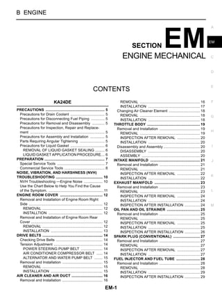
  • 12. EM-12 [KA24DE] ENGINE ROOM COVER ENGINE ROOM COVER PFP:14049 Removal and Installation of Engine Room Right Side EBS00ALX REMOVAL 1. Open engine compartment LH cover and secure it. 2. Remove RH seat. Refer to SE-4, "FRONT SEAT" . 3. Partially remove floor carpet. 4. Disconnect harness protector secured together at front right. Disconnect harness connector to move har- ness routed on top of engine compartment RH cover aside. 5. Move parking brake lever and cable from engine compartment RH cover. Refer to PB-3, "PARKING BRAKE SYSTEM" . 6. Remove mounting bolts, and remove engine compartment RH cover. CAUTION: When taking it out of vehicle, do not allow it to interfere with vehicle. INSTALLTION q Install in reverse order of removal following instructions below. 1. Temporarily tighten bolt No. 1 shown in the figure. 2. Tighten bolt No. 2 shown in figure to specified torque. 3. Tighten other bolts except bolt “A” shown in the figure (bolt No. 1 is included) to specified torque in any given order. 4. Close engine compartment LH cover. 5. Tighten bolt “A” shown in the figure to specified torque. Removal and Installation of Engine Room Rear Cover EBS00ALY REMOVAL 1. Move folded seat on engine compartment rear cover side rearward, if applicable. 2. Partially remove floor carpet. 3. Remove mounting bolts, and remove engine compartment rear cover. KBIA0741E 1. Engine room right side cover 2. Parking brake lever 3. Engine room left side cover 4. Parking brake cable 5. Harness 6. Harness protector
  • 13. ENGINE ROOM COVER EM-13 [KA24DE] C D E F G H I J K L M A EM INSTALLATION Following instructions below, install in reverse order of removal. 1. Tighten bolts No. 1 to No. 3 shown in the figure to specified torque in this order. 2. Tighten other bolts to specified torque in any given order. KBIA0742E
  • 14. EM-14 [KA24DE] DRIVE BELTS DRIVE BELTS PFP:02117 Checking Drive Belts EBS007K4 WARNING: Be sure to perform when the engine is stopped. q Inspection should be done only when engine is cold, or over 30 minutes after engine is stopped. q Measure belt tension with tension meter (special service tool) at points marked shown in the figure. q Measure belt deflection by applying load of 98.1 N {10 kg} to . Unit: mm (in) Tension Adjustment EBS00AM2 CAUTION: q When belt is replaced with a new one, tighten it a little stronger than current one to accommodate for insufficient adaptability with pulley grooves. q When tension of belt being used exceeds ″Retightening limit″, adjust it to value for ″Used belt″. q When installing belt, make sure that it is correctly engaged with pulley groove. q Keep oil and water away from belt. q Do not twist or bend belt excessively. POWER STEERING PUMP BELT 1. Open and fix engine compartment LH cover. 2. Loosen idler pulley lock nut (A) and adjust tension by turning adjusting bolt (B). q For specified belt tension, refer to EM-14, "Checking Drive Belts" . 3. Tighten nut (A). AIR CONDITIONER COMPRESSOR BELT 1. Open and fix engine compartment LH cover (passenger side for RHD models or driver-side for LHD mod- els). 2. Loosen idler pulley lock nut (C) and adjust tension by turning adjusting bolt (D). q For specified belt tension, refer to EM-14, "Checking Drive Belts" . 3. Tighten nut (C). PBIC0422E Deflection adjustment Used belt New belt Limit After adjustment Alternator 11 (0.43) 7 - 8 (0.28 - 0.31) 6 - 7 (0.24 - 0.28) Air conditioner compressor 13 (0.51) 8 - 10 (0.31 - 0.39) 7 - 8 (0.28 - 0.31) Power steering oil pump 13 (0.51) 8 - 10 (0.31 - 0.39) 7 - 8 (0.28 - 0.31) Applied pushing force 98 N (10 kg, 72 lb) : 25.5 - 32.4 N·m (2.6 - 3.3 kg-m, 19 - 23 ft-lb) EMK0571D
  • 15. DRIVE BELTS EM-15 [KA24DE] C D E F G H I J K L M A EM ALTERNATOR AND WATER PUMP BELT 1. Remove front-side under cover. 2. Remove RH seat. Refer to SE-4, "FRONT SEAT" . 3. Remove engine compartment RH cover. Refer to EM-12, "ENGINE ROOM COVER" . 4. Loosen alternator mounting bolt (E) and adjuster lock bolt (F), and adjust tension by turning adjusting nut (G). q For specified belt tension, refer to EM-14, "Checking Drive Belts" . 5. Tighten bolts (E), (F) and (G). Removal and Installation EBS007K6 REMOVAL q Loosen each belt while referring to "Adjustment", and remove them one by one starting from the one in front. INSTALLATION 1. Install belts to pulley in reverse order of removal. 2. Adjust belt tension. CAUTION: q When checking belt tension immediately after installation, first, adjust to specified value. Then, after turning crankshaft more than two turns, re-adjust to specified value to avoid variation in deflection between pulleys. q Tighten idler pulley lock nut by hand and measure tension without looseness. 3. Tighten each adjusting bolt and nut to the specified torque. 4. Make sure that tension of each belt is within the standard. : 25.5 - 32.4 N·m (2.6 - 3.3 kg-m, 19 - 23 ft-lb) : 45.1 - 59.8 N·m (4.6 - 6.1 kg-m, 34 - 44 ft-lb) for E bolt : 15.7 - 20.6 N·m (1.6 - 2.1 kg-m, 12 - 15 ft-lb) for F bolt : 6.5 - 7.6 N·m (0.67 - 0.77 kg-m, 58 - 67 in-lb) for G bolt
  • 16. EM-16 [KA24DE] AIR CLEANER AND AIR DUCT AIR CLEANER AND AIR DUCT PFP:16500 Removal and Installation EBS007K8 REMOVAL 1. Remove rear-side under cover. 2. Open and fix engine room LH cover. 3. Remove RH seat. Refer to SE-4, "FRONT SEAT" . 4. Remove engine room RH cover. Refer to EM-12, "ENGINE ROOM COVER" . 5. Remove floor cover behind RH seat. 6. Disconnect harness connector from airflow sensor. KBIA0821E 1 PCV hose 2 Air duct 3 Collar 4 Grommet 5 Clamp 6 Collar 7 Grommet 8 Resonator 9 Clamp 10 Resonator 11 Clamp 12 Air hose 13 Resonator 14 Clamp 15 Mass air flow meter 16 Air cleaner case 17 Grommet 18 Air cleaner element 19 Washer 20 Wing nut 21 Seal ring 22 Dust pan 23 Washer 24 Wing nut 25 Dust exhaust valve 26 Grille 27 Screw 28 Air duct 29 Grommet 30 Air duct 31 Resonator 32 Grommet 33 Collar 34 Resonator 35 Clamp
  • 17. AIR CLEANER AND AIR DUCT EM-17 [KA24DE] C D E F G H I J K L M A EM 7. For correct installation, make matching marks on each connec- tion. 8. Remove from engine side after separating the system with the following procedure. a. Remove PCV hose (A). b. Remove air duct (B). c. Separate air hose (C) and resonator (D). d. Remove resonator (E). e. Remove air hose (C). f. Remove resonator (D). g. Remove mass air flow sensor (F). CAUTION: q Handle with care, avoiding any shocks. q Do not disassemble it. q Do not touch sensor part. h. After removing mud flap of front RH wheel, remove resonator (G). i. When removing following parts, remove EVAP canister, and set it aside. j. Remove resonator (H). k. Remove air cleaner case (I). 9. When removing components inside vehicle on right-hand, remove them with the following procedure. a. Remove components up to air cleaner case (I), referring to step 8. b. Remove intake grille from outside of vehicle. c. Remove kicking plate on RH side, and lift up panel under RH side seat belt anchor. d. Lift up air duct (J) from vehicle opening, and separate it from air duct (K). e. Pull and remove air duct (K). f. Remove air duct (J) from mounting hole of air duct (K). INSTALLATION Install in reverse order of removal, paying attention to points below. q After aligning matching marks marked when removing, install each connection, and firmly tighten clamps. q Install dust drain valve so that its opening is along circumfer- ence. KBIA0822E KBIA0902E KBIA0819E
  • 18. EM-18 [KA24DE] AIR CLEANER AND AIR DUCT Changing Air Cleaner Element EBS0096T REMOVAL NOTE: q Mark ″*″ in the figure shows part of lift arm. q For replacement of air cleaner element, it is not necessary to lift up vehicle. 1. Remove brake pipe protector under vehicle, behind front RH wheel. 2. Remove 3 clips, and the cover at the bottom of air cleaner case. 3. Remove wing nut, dust pan under air cleaner case, and then air cleaner element. INSTALLATION Install in the reverse order of removal. KBIA0749E
  • 19. THROTTLE BODY EM-19 [KA24DE] C D E F G H I J K L M A EM THROTTLE BODY PFP:16298 Removal and Installation EBS008X7 REMOVAL 1. Remove RH seat. Refer to SE-4, "FRONT SEAT" . 2. Remove engine compartment RH cover. Refer to EM-12, "ENGINE ROOM COVER" . 3. Remove air duct on throttle body. Refer to EM-16, "AIR CLEANER AND AIR DUCT" . 4. Disconnect accelerator cable, and set it aside. 5. Disconnect harness connector. 6. Disconnect water hose. q After disconnection, plug the hose to prevent coolant leaks. 7. Loosen mounting bolts in reverse order shown in the figure, and remove throttle body. KBIA0823E 1 Bracket 2 Throttle position sensor harness 3 Water hose 4 Throttle body 5 Bracket 6 Water hose 7 Gasket 8 Intake manifold PBIC0424E
  • 20. EM-20 [KA24DE] THROTTLE BODY INSPECTION AFTER REMOVAL q If idle is rough when engine is cold or warmed up, check and adjust the fast idle cam (FIC). Refer to EC- 28, "Fast Idle Cam (FIC) Inspection and Adjustment" . INSTALLATION Install in reverse order of removal, paying attention to points below. q For throttle body, tighten mounting bolts in two steps in the numerical order shown in the figure. q For adjustment of accelerator cable, refer to ACC-3, "ACCEL- ERATOR CONTROL SYSTEM (KA24DE)" . Disassembly and Assembly EBS008X8 DISASSEMBLY Disassemble referring to the component illustration. ASSEMBLY Assemble in reverse order of disassembly, paying attention to points below. q Insert throttle position sensor into throttle body, with connectors positioned as shown in the figure. Then rotate it in the direction shown by arrow and temporarily tighten mounting screws. q While they are turned in direction shown by arrow, circumfer- ence of sensor hits projection. Avoid hitting projection by giving slight space, and insert projection into inside of mounting screw long hole. (It is temporarily held in place by counter-action of spring.) q After adjustment on vehicle, tighten mounting screws. For adjusting procedure, refer to EC-45, "Basic Inspection" . 1st step : 8.8 - 10.8 N·m (0.9 - 1.1 kg-m, 78 - 95 in-lb) 2nd step : 17.7 - 21.6 N·m (1.8 - 2.2 kg-m, 13 - 15 ft-lb) PBIC0424E PBIC0425E 1 Throttle body 2 Throttle position sensor 3 IACV-FICD solenoid valve 4 Washer 5 Spring 6 plunger 7 Gasket 8 IACV-AAC valve PBIC0426E
  • 21. INTAKE MANIFOLD EM-21 [KA24DE] C D E F G H I J K L M A EM INTAKE MANIFOLD PFP:14003 Removal and Installation EBS007K9 REMOVAL 1. Release fuel pressure. Refer to EC-27, "Fuel Pressure Release" . 2. Drain coolant. Refer to CO-9, "ENGINE COOLANT" . 3. Remove RH seat. Refer to SE-4, "FRONT SEAT" . 4. Remove engine compartment RH cover and rear cover. Refer to EM-12, "ENGINE ROOM COVER" . 5. Remove floor cover behind RH seat. PBIC0427E 1 Bracket 2 Grounding wire 3 Bracket 4 Vacuum hose 5 Intake manifold 6 Heater pipe 7 Water hose 8 Water hose 9 Intake manifold support 10 Vacuum hose 11 Thermal transmitter 12 Water outlet 13 Gasket 14 Water hose 15 PCV hose 16 Gasket 17 Air relief plug 18 Gasket 19 Engine coolant temperature sensor 20 Gasket
  • 22. EM-22 [KA24DE] INTAKE MANIFOLD 6. Move aside main harness above intake manifold. 7. Disconnect PCV hose between rocker cover and air duct. 8. Remove air duct between throttle body and mass air flow sensor. Refer to EM-16, "AIR CLEANER AND AIR DUCT" . 9. Remove throttle body. Refer to EM-19, "THROTTLE BODY" . 10. Remove fuel tube and injector assembly. Refer to EM-28, "FUEL INJECTOR AND FUEL TUBE" . 11. Disconnect radiator hose (upper). 12. Disconnect hoses connected to intake manifold. NOTE: Separate water hose and PCV hose behind intake manifold when removing intake manifold. 13. Remove intake manifold with the following procedure. a. Loosen mounting bolts and nuts in reverse order shown in the figure. b. Pull out stud bolts on rear. c. Disconnect water hose and PCV hose on back side, and remove intake manifold. INSPECTION AFTER REMOVAL Surface Distortion q Using straightedge and feeler gauge, inspect surface distortion of intake manifold. INSTALLATION Assemble in reverse order of removal, paying attention to the following. Intake Manifold Bolts q Tighten in numerical order as shown in the figure. Water Outlet q Install gasket so that identification mark face as shown in component parts drawing. PBIC0428E Limit : 0.1 mm (0.004 in) PBIC0429E : 15.7 - 18.6 N·m (1.6 - 1.8 kg-m, 12 - 13 ft- lb) PBIC0428E
  • 23. EXHAUST MANIFOLD EM-23 [KA24DE] C D E F G H I J K L M A EM EXHAUST MANIFOLD PFP:14004 Removal and Installation EBS008RQ REMOVAL 1. Remove under cover on rear side. 2. Remove exhaust front tube. Refer to EX-2, "EXHAUST SYSTEM" . 3. Open and fix engine compartment LH cover. 4. Remove heated oxygen sensor with the following procedure. a. Remove engine compartment rear cover. Refer to EM-12, "ENGINE ROOM COVER" . b. Disconnect heated oxygen sensor harness connector from bracket on intake manifold No. 4 port, and remove all harness clamps. c. Using socket for heated oxygen sensor removal and installation (special service tool), remove heated oxygen sensor. 5. Remove exhaust manifold cover. KBIA0825E 1 Exhaust manifold 2 Gasket 3 Heated oxygen sensor 4 Oil level gauge guide 5 Exhaust manifold cover 6 Bracket KBIA0826E
  • 24. EM-24 [KA24DE] EXHAUST MANIFOLD 6. Loosen mounting nuts in reverse order shown in the figure, and remove exhaust manifold. INSPECTION AFTER REMOVAL q Using straightedge and feeler gauge, inspect surface distortion of intake manifold. INSTALLATION Install in the reverse order of removal, paying attention to the follow- ing. q Tighten in numerical order as shown in the figure. INSPECTION AFTER INSTALLATION Start engine, and check for exhaust gas leakage and unusual noise by increasing engine speed. PBIC0430E Limit : 0.3 mm (0.012 in) PBIC0431E : 37.3 - 48.1 N·m (3.8 - 4.9 kg-m, 28 - 35 ft-lb) PBIC0430E
  • 25. OIL PAN AND OIL STRAINER EM-25 [KA24DE] C D E F G H I J K L M A EM OIL PAN AND OIL STRAINER PFP:11110 Removal and Installation EBS007KB REMOVAL WARNING: To avoid the danger of being scalded, never drain the engine oil when the engine is hot. 1. Remove under covers on front-side, and rear-side. 2. Drain engine oil. Refer to LU-5, "ENGINE OIL" . 3. Loosen mounting bolts in reverse order shown in the figure, and remove them. NOTE: There are no screw holes in the area marked with on cylinder block. (No mounting bolts.) 4. Using a seal cutter (special service tool), separate liquid gasket, and remove oil pan. 5. Remove oil strainer. INSPECTION AFTER REMOVAL Check oil strainer and clean it if any object attached. INSTALLATION Install in the reverse order of removal paying attention to the following. PBIC0432E 1 Gasket 2 Oil strainer 3 Oil pan drain plug washer 4 Oil pan drain plug 5 Oil pan SEM980F
  • 26. EM-26 [KA24DE] OIL PAN AND OIL STRAINER Installing Oil Pan 1. Apply liquid gasket thoroughly as shown in illustration. q Use Genuine Liquid Gasket or equivalent. 2. Tighten mounting bolts in numerical order as shown in the fig- ure. NOTE: There are no screw holes in the area marked with on cylinder block. (No mounting bolts.) Installing Drain Plug Washer Refer to illustration of component parts for installation direction. INSPECTION AFTER INSTALLATION Check for leakage of engine oil when engine is warmed. PBIC0433E SEM985F
  • 27. SPARK PLUG (CONVENTIONAL) EM-27 [KA24DE] C D E F G H I J K L M A EM SPARK PLUG (CONVENTIONAL) PFP:22401 Removal and Installation EBS008YM REMOVAL 1. Open and fix engine compartment LH cover. 2. Disconnect high-tension cables from rocker cover. 3. Remove spark plugs with a spark plug wrench (commercial ser- vice tool). q Remove and install No. 4 cylinder by connecting extension bar of 75 mm and universal socket to spark plug wrench. INSPECTION AFTER REMOVAL Check spark plug gap. Adjust or replace if necessary. Spark plug: q Use a wire brush for cleaning, if necessary. INSTALLATION Install in the reverse order of removal, paying attention to the following. q Refer to EM-30, "ROCKER COVER" for installation of spark plug cap and high-tension cables. SMA581C Standard : 1.0 - 1.1 mm (0.039 - 0.043 in) Make NGK Standard type BKR5E-11 Cold type BKR6E-11 BKR7E-11 SMA476 Spark plug: : 20 - 29 N·m ( 2.0 - 3.0 Kg-m, 14 - 22 ft-lb)
  • 28. EM-28 [KA24DE] FUEL INJECTOR AND FUEL TUBE FUEL INJECTOR AND FUEL TUBE PFP:16600 Removal and Installation EBS007KE CAUTION: q Apply new engine oil when installing the parts that specified to do so in the figure. REMOVAL 1. Release fuel pressure. Refer to EC-27, "Fuel Pressure Release" . 2. Remove RH seat. Refer to SE-4, "FRONT SEAT" . 3. Remove engine compartment RH cover. Refer to EM-12, "ENGINE ROOM COVER" . 4. Disconnect PCV hose between rocker cover and air duct. 5. Remove air duct on throttle body. Refer to EM-16, "AIR CLEANER AND AIR DUCT" . 6. Disconnect fuel injector harness connector. 7. Move aside main harness above intake manifold. 8. Disconnect vacuum hose from fuel tube. 9. Disconnect fuel feed hose and fuel return hose. CAUTION: Plug hoses to prevent fuel from draining. 10. Remove fuel tube and injector assembly. CAUTION: Do not incline it, or remaining fuel in pipes may drain from pipes. KBIA0827E 1 Fuel tube 2 Vacuum hose 3 Fuel feed hose 4 Clip 5 O-ring 6 Fuel injector 7 Fuel return hose 8 Vacuum hose 9 O-ring 10 Fuel pressure regulator
  • 29. FUEL INJECTOR AND FUEL TUBE EM-29 [KA24DE] C D E F G H I J K L M A EM 11. Expand and remove clips securing fuel injectors. 12. Extract fuel injectors straight from fuel tubes. q Be careful not to damage injector nozzles during removal. q Do not bump or drop fuel injectors. q Do not disassemble. INSTALLATION 1. Carefully install O-rings, including the one used with the pressure regulator. q Lubricate O-rings by smearing new engine oil. q Be careful not to damage O-rings and surfaces for O-ring sealing with service tools, finger nails or clips. Do not expand or twist O-rings. q Discard old clips; replace with new ones. 2. Position clips in grooves on fuel injectors. q Make sure that protrusions of fuel injectors are aligned with cutouts of clips after installation. 3. Align protrusions of fuel tubes with those of fuel injectors. 4. Do not incline it, or remaining fuel in pipes may drain from pipes. q Insert hose until its end touches bulge on fuel tube. Install clamp, avoiding bulge, and securely tighten it. 5. Tighten fuel tube assembly mounting bolts alternatively in two steps. 6. Connect fuel feed nose and fuel return hose. q Insert hose until its end touches bulge on fuel tube. Install clamp, avoiding bulge, and securely tighten it. 7. Install all removed parts in the reverse order of removal. INSPECTION AFTER INSTALLATION Check on Fuel Leakage 1. Start the engine, and run it for a few minutes with engine at idle. 2. Stop the engine, and check for fuel leakage both visually and by odor of gasoline. NOTE: Use mirrors for checking on invisible points. CAUTION: Do not touch the engine immediately after stopped, as engine becomes extremely hot. PBIC0227E 1st step : 7.8 - 10.8 N·m (0.8 - 1.1 kg-m, 69 - 95 ft-lb) 2nd step :15.7 - 18.6 N·m (1.6 - 1.8 kg-m, 12 - 13 ft-lb) PBIC0227E
  • 30. EM-30 [KA24DE] ROCKER COVER ROCKER COVER PFP:13264 Removal and Installation EBS007KF REMOVAL 1. Open and fix engine compartment LH cover. 2. Remove engine compartment rear cover. Refer to EM-12, "ENGINE ROOM COVER" . 3. Disconnect PCV hose. 4. Disconnect spark plug cap and high-tension cables, and set them aside. 5. Loosen mounting bolts in reverse order shown in the figure, and remove rocker cover. INSTALLATION Install in the reverse order of removal, paying attention to the following. KBIA0828E 1 PCV hose 2 Oil filler cap 3 Rocker cover 4 Gasket 5 Gasket PBIC0434E
  • 31. ROCKER COVER EM-31 [KA24DE] C D E F G H I J K L M A EM Installing Rocker Cover 1. Apply liquid gasket to positions shown in the figure (semicircular plug seal on engine side: total 4). q Use genuine liquid gasket or equivalents. 2. Install rocker cover so that semicircular plug part on rocker cover gasket is securely inserted into mounting part on engine. 3. Tighten mounting bolts in numerical order shown in the figure. NOTE: No.1 and No.2 means dual step tightening. Spark Plug Cap and High Tension Cable q Install them to clips, and perform wiring of cables, referring to the figure for correct placement. PBIC0435E PBIC0434E EMK0592D
  • 32. EM-32 [KA24DE] CAMSHAFT CAMSHAFT PFP:13001 Removal and Installation EBS007KG CAUTION: Apply new engine oil to parts marked in illustration before installation. REMOVAL 1. Remove following parts. q Power steering pump belt (Refer to EM-14, "DRIVE BELTS" .) q Power steering pump support bracket q Idler pulley bracket for power steering pump belt q Rocker cover (Refer to EM-30, "ROCKER COVER" .) 2. Set No.1 cylinder to TDC in compression stroke. a. Rotate crankshaft pulley clockwise and align notch of matching marks (yellow paint) to timing indicator on front cover. PBIC0436E 1 Camshaft bracket 2 Camshaft (Intake) 3 Camshaft sprocket (Intake) 4 Camshaft sprocket (Exhaust) 5 Camshaft (Exhaust) PBIC0437E
  • 33. CAMSHAFT EM-33 [KA24DE] C D E F G H I J K L M A EM b. At same time, make sure that matching marks on camshaft sprockets are located as shown in the figure. Make matching marks on secondary timing chain links with paint. q If dislocated, rotate crankshaft pulley one more turn to line up matching marks to positions in the figure. 3. Push secondary timing chain tensioner with metal bar, then fix it with stopper pin. CAUTION: Do not remove cylinder head front cover. NOTE: When cylinder head front cover is removed, cylinder head gas- ket needs to be replaced. q Using hard wire, make a stopper pin as shown in the figure. 4. Hold camshaft hexagonal head with 26 mm (1.02 in) spanner, and loosen camshaft sprocket bolt. NOTE: Each camshaft has two camshaft hexagonal heads: one in front, and the other in rear. PBIC0438E PBIC0439E PBIC0440E EMK0468D
  • 34. EM-34 [KA24DE] CAMSHAFT 5. Remove camshaft sprockets. q Hold secondary timing chain in place, using chain stopper (special service tool) to prevent it from slipping from idler sprocket. 6. Loosen mounting bolts of camshaft brackets in several steps in the numerical order shown in the figure, and remove them. 7. Remove camshaft. 8. Remove adjusting shim and valve lifter. q Check mounting positions, and store them without mixing them up. INSTALLATION 1. Install valve lifters and adjusting shims. q Install them in their original positions. q Install adjusting shims with their stamp marks facing downward (valve lifter side). 2. Install camshaft. q Intake and exhaust are identified by direction of No. 1 cylinder cam nose when knock pin at front end faces straight upward. q Install camshafts so that knock pins at front end face straight upward (position of No.1 cylinder at compression TDC). PBIC0441E PBIC0442E For intake: Cam nose faces toward intake manifold side For exhaust: Cam nose faces toward exhaust manifold side PBIC0443E PBIC0444E
  • 35. CAMSHAFT EM-35 [KA24DE] C D E F G H I J K L M A EM 3. Install camshaft bracket. q Install them in their original positions and directions, referring to mark on top surface of camshaft bracket. 4. Tighten camshaft bracket mounting bolts in two steps in numeri- cal order shown in the figure. CAUTION: Tighten them from outside toward inside. 5. Install camshaft sprockets. q Camshaft sprockets are common for intake and exhaust sides. Sprockets have two matching marks. When aligning matching marks, refer to the figure. q Align matching mark of camshaft sprocket and that of second- ary timing chain made on it when removed. Then install cam- shaft. q If they are not aligned, align them by turning hexagonal part of camshaft with a spanner. q Make sure that timing chain does not slip on idler pulley, and remove chain stopper (special service tool). q Hold hexagonal part of camshaft with spanner, and tighten camshaft sprocket mounting bolt. NOTE: Each camshaft has one hexagonal part at both front and rear, respectively. 6. Pull out stopper pins from secondary timing chain tensioner. 7. Check and adjust valve clearance. Refer to EM-38, "Valve Clearance" . 8. Install other parts in reverse order of removal. INSPECTION AFTER REMOVAL Camshaft Runout q Put V block on, and support No.1 and No.5 journal of camshaft. q Set dial gauge vertically to No.3 journal. q Turn camshaft to one direction with hands, and measure cam- shaft runout (Total indicator reading) on dial gauge. PBIC0445E 1st step : 2.0 N·m (0.2 kg-m, 18 in-lb) 2nd step :9.0 - 11.8 N·m (0.92 - 1.2 kg-m, 80 - 104 ft-lb) PBIC0442E PBIC0438E Standard : Less than 0.04 mm (0.0016 in) Limit : 0.08 mm (0.0031 in) SEM926C
  • 36. EM-36 [KA24DE] CAMSHAFT Camshaft Cam Height 1. Measure camshaft cam height. 2. If wear is beyond the limit, replace camshaft. Camshaft Journal Clearance Outer Diameter of Camshaft Journal q Measure outer diameter of camshaft journal. Inner Diameter of Camshaft Bracket q Tighten camshaft bracket bolt with specified torque. q Using inside micrometer, measure inner diameter of camshaft bracket. Calculation of Camshaft Journal Clearance (Journal clearance) = (inner diameter of camshaft bracket) – (outer diameter of camshaft journal) q When out of the specified range above, replace either or both camshaft and cylinder head. NOTICE: Inner diameter of camshaft bracket is manufactured together with cylinder head. Replace the whole cylinder head assembly. Camshaft End Play q Install dial gauge in thrust direction on front end of camshaft. Measure end play of dial gauge when camshaft is moved for- ward/backward (in direction to axis). q When out of the specified range, replace with new camshaft and measure again. q When out of the specified range again, replace with new cylinder head. Standard: Intake: 41.755 - 41.945 mm (1.644 - 1.651 in) Exhaust: 41.815 - 42.005 mm (1.646 - 1.654 in) Limit: Intake and exhaust: 0.2 mm (0.008 in) PBIC0039E Standard : 27.935 - 27.955 mm (1.0998 - 1.1006 in) PBIC0040E Standard : 28.000 - 28.025 mm (1.1024 - 1.1033 in) Standard : 0.045 - 0.090 mm (0.0018 - 0.0035 in) Limit : 0.15 mm (0.0059 in) SEM295D Standard : 0.070 - 0.148 mm (0.0028 - 0.0058 in) Limit : 0.2 mm (0.008 in) PBIC0446E
  • 37. CAMSHAFT EM-37 [KA24DE] C D E F G H I J K L M A EM Camshaft Sprocket Runout 1. Install camshaft in cylinder head. 2. Install camshaft sprocket to camshaft. 3. Measure camshaft sprocket runout. 4. If it exceeds the limit, replace camshaft sprocket. Valve Lifter and Adjusting Shim q Check if surface of valve lifter and adjusting shim has any wear or cracks. Valve Lifter Clearance Outer Diameter of Valve Lifter q Measure outer diameter of valve lifter. Valve Lifter Hole Diameter q Using inside micrometer, measure diameter of valve lifter hole of cylinder head. Calculation of Valve Lifter Clearance (Valve lifter clearance) = (hole diameter of valve lifter) – (outer diam- eter of valve lifter) q When out of specified range, referring to each specification of outer and inner diameter, replace either or both valve lifter and cylinder head. Limit : Less than 0.15 mm (0.0059 in) KBIA0181J SEM160D Standard : 33.960 - 33.975 mm (1.3370 - 1.3376 in) SEM961E Standard : 34.000 - 34.021 mm (1.3386 - 1.3394 in Standard : 0.025 - 0.061 mm (0.0010 - 0.0024 in PBIC0447E
  • 38. EM-38 [KA24DE] CAMSHAFT Valve Clearance EBS007KH INSPECTION Check valve clearance while engine is warm but not running. 1. Remove rocker cover and all spark plugs. 2. Set No. 1 cylinder at TDC on its compression stroke. q Align pointer with TDC mark on crankshaft pulley. q Check that valve lifters on No. 1 cylinder are loose and valve lift- ers on No. 4 are tight. If not, turn crankshaft one revolution (360°) and align as above. 3. Check only those valves shown in the figure. 4. Using a feeler gauge, measure clearance between valve lifter and camshaft. q Record any valve clearance measurements which are out of specification. They will be used later to determine the required replacement adjusting shim. 5. Turn crankshaft one revolution (360°) and align mark on crank- shaft pulley with pointer. 6. Check those valves shown in the figure. q Use the same procedure as mentioned in step 4. 7. If all valve clearances are within specification, install the follow- ing parts. q Rocker cover q All spark plugs ADJUSTMENT Adjust valve clearance while engine is cold. PBIC0437E AEM382 Valve clearance (HOT) : Intake 0.31 - 0.39 mm (0.012 - 0.015 in) Exhaust 0.39 - 0.47 mm (0.015 - 0.019 in) SEM304D AEM383
  • 39. CAMSHAFT EM-39 [KA24DE] C D E F G H I J K L M A EM 1. Turn crankshaft to position cam lobe on camshaft of valve that must be adjusted upward. 2. Place Tool (A) around camshaft as shown in figure. 3. Rotate Tool (A) so that lifter is pushed down. Before placing Tool (A), rotate notch toward center of cylinder head (See figure.), to simplify shim removal later. CAUTION: Be careful not to damage cam surface with Tool (A). 4. Place Tool (B) between camshaft and the edge of the valve lifter to retain valve lifter. CAUTION: q Tool (B) must be placed as close to camshaft bracket as possible. q Be careful not to damage cam surface with Tool (B). 5. Remove Tool (A). 6. Rotate adjusting shim until hole is visible. Blow air into the hole to separate adjusting shim from valve lifter. 7. Remove adjusting shim using a small screwdriver and a mag- netic finger. SEM515EB SEM516EB SEM999F SEM517EB
  • 40. EM-40 [KA24DE] CAMSHAFT 8. Determine replacement adjusting shim size as follows. a. Using a micrometer determine thickness of removed shim. b. Calculate thickness of new adjusting shim so valve clearance comes within specified values. R = Thickness of removed shim N = Thickness of new shim M = Measured valve clearance (Hot) Shims are available in thicknesses from 1.96 mm (0.0772 in) to 2.68 mm (0.1055 in), in steps of 0.02 mm (0.0008 in). c. Select new shim with thickness as close as possible to calcu- lated value. Refer to EM-88, "VALVE" . 9. Install new shim using a suitable tool. q Install with the surface on which the thickness is stamped facing down. 10. Place Tool (A) as mentioned in steps 2 and 3. 11. Remove Tool (B). 12. Remove Tool (A). 13. Recheck valve clearance. Refer to EM-38, "INSPECTION" . Valve clearance: Unit: mm (in) *: Approximately 20°C (68°F) Intake N = R + [ M – 0.35 mm (0.0138 in)] Exhaust N = R + [ M – 0.43 mm (0.0169 in)] SEM145D SEM308D Hot Cold* (reference data) Intake 0.31 - 0.39 (0.012 - 0.015) 0.28 - 0.36 (0.011 - 0.014) Exhaust 0.39 - 0.47 (0.015 - 0.019) 0.34 - 0.42 (0.013 - 0.017)
  • 41. SECONDARY TIMING CHAIN EM-41 [KA24DE] C D E F G H I J K L M A EM SECONDARY TIMING CHAIN PFP:13028 Removal and Installation EBS008Z5 CAUTION: Apply new engine oil to parts marked in illustration before installation. NOTE: q This section describes removal and installation procedure of secondary timing chain along with removal and installation of cylinder head. q Procedure for removal and installation of camshaft is described in EM-32, "CAMSHAFT" , as it is different from description in this section. REMOVAL 1. Release fuel pressure. Refer to EC-27, "Fuel Pressure Release" . 2. Drain engine coolant from radiator and cylinder block. Refer to CO-9, "ENGINE COOLANT" . PBIC0448E 1 Camshaft (Intake) 2 Camshaft sprocket (Intake) 3 Camshaft sprocket (Exhaust) 4 Camshaft (Exhaust) 5 Power steering pump bracket 6 Idler pulley and bracket ASSY 7 Cylinder head front cover 8 Secondary timing chain 9 Washer 10 Idler sprocket 11 Idler shaft 12 Chain tensioner
  • 42. EM-42 [KA24DE] SECONDARY TIMING CHAIN 3. Remove driver seat. Refer to SE-4, "FRONT SEAT" . 4. Remove engine compartment RH cover and rear cover. Refer to EM-12, "ENGINE ROOM COVER" . 5. Remove floor cover behind RH seat. 6. Adjust No. 1 cylinder to TDC position in compression stroke. Refer to EM-32, "CAMSHAFT" . 7. Remove following parts. q Intake manifold: Refer to EM-21, "INTAKE MANIFOLD" . q Exhaust manifold: Refer to EM-23, "EXHAUST MANIFOLD" . q Drive belts: Refer to EM-14, "DRIVE BELTS" . q Radiator shroud (Upper and lower) q Cooling fan: Refer to CO-20, "COOLING FAN" . 8. Remove power steering oil pump. Fix it along with reservoir tank on vehicle with rope or similar means. CAUTION: Fix reservoir tank to prevent power steering fluid from leaking. 9. Remove power steering pump bracket, and idler pulley bracket for power steering pump belt. 10. Remove rocker cover. Refer to EM-30, "ROCKER COVER" . 11. Remove camshaft sprocket, and camshaft. Refer to EM-32, "CAMSHAFT" . NOTE: The following steps in removal procedure are not necessary at this point. q Step 2: Application of matching marks to secondary timing chain q Step 5: Fixing of secondary timing chain 12. Remove cylinder head front cover with the following procedure. a. Remove all mounting bolts (A - G) of cylinder head front cover. b. Completely loosen cylinder head bolts in reverse order shown in the figure. q Do not remove cylinder head at this point. (Remove it in step 16.) c. Slightly tap cylinder head front cover from back side with an appropriate wooden bar to remove it. PBIC0449E SEM274D EMK0486D
  • 43. SECONDARY TIMING CHAIN EM-43 [KA24DE] C D E F G H I J K L M A EM 13. Remove secondary timing chain from idler sprocket small-diam- eter side. 14. Remove chain tensioner. 15. Remove idler sprocket and idler shaft with the following procedure. 1. Make a matching mark on primary timing chain with paint at a location that corresponds to the matching mark on idler sprocket large-diameter side. 2. Compress sleeve of primary timing chain tensioner, and hold it with stopper pin (self-made tool). – Make stopper pin the size shown in the figure. – Use hard wire for material. PBIC0450E PBIC0451E PBIC0452E PBIC0440E
  • 44. EM-44 [KA24DE] SECONDARY TIMING CHAIN 3. Fix primary timing chain by inserting chain stopper (special service tool) to prevent it from slipping from crankshaft sprocket. – Chain stopper is difficult to pull out because of interference with idler sprocket large-diameter side when being removed. Use it after circumference of upper surface is chamfered. 4. Remove idler sprocket, and idler shaft. CAUTION: Do not carry idler shaft with idler sprocket large-diameter side facing downward to prevent it from falling off. 16. Remove cylinder head and cylinder head gasket. INSPECTION AFTER REMOVAL Timing Chain Check timing chain for cracks and excessive wear at roller links. Replace chain if necessary. Idler Sprocket End Play q Install idler sprocket to cylinder head, and tighten mounting bolts to specified torque. q Set dial gauge to idler sprocket front end. q Move idler sprocket in thrust direction (back-and-forth), and read indication on gauge. EMK0490D PBIC0453E SEM984C Standard : 0.2 - 0.3 mm (0.008 - 0012 in) EMK0538D
  • 45. SECONDARY TIMING CHAIN EM-45 [KA24DE] C D E F G H I J K L M A EM Idler Sprocket Oil Clearance Idler Sprocket Inner Diameter q Using inside micrometer measure the inner diameter. Idler Shaft Outer Diameter q Using micrometer measure the outer diameter. Calculation of Idler Sprocket Oil Clearance q (Idler sprocket oil clearance) = (Idler sprocket inner diameter) – (Idler shaft outer diameter) q If outside the standard, replace either idler sprocket, idler shaft, or both, referring to standard value of each single unit. INSTALLATION NOTE: q The figure shows the relationship between the mating mark on each timing chain and that on the corresponding sprocket, with the components installed. 1. Make sure that stopper pin of primary timing chain tensioner is in place. If not, reinstall it. 2. Install cylinder head gasket. 3. Temporarily install cylinder head assembly. q Install cylinder head assembly to cylinder block by aligning it with dowel pins. Standard : 29.025 - 29.050 mm (1.1427 - 1.1437 in) EMK0539D Standard : 28.987 - 29.000 mm (1.1412 - 1.1420 in) EMK0129D Standard : 0.025 - 0.063 mm (0.0010 - 0.0025 in) KBIA0892E
  • 46. EM-46 [KA24DE] SECONDARY TIMING CHAIN q Temporarily install rear-most two cylinder head bolts shown in the figure. q Install washers to mounting bolt seats on cylinder head. NOTE: Washers are not directional. q Apply engine oil to bolt threads and seats. q Support bolt approximately 10 mm (0.39 in) above seating position. (Make room under lower end, when lifting up front end of cylinder head.) 4. Install idler sprocket. a. Install idler shaft to idler sprocket. b. Install washer so that flat side faces idler sprocket. Refer to com- ponent illustrationEM-41 . c. Align matching mark painted on primary timing chain during removal with the one on idler sprocket large-diameter side. Then install it to cylinder head. d. Remove chain stopper from primary timing chain. e. Remove stopper pin from primary timing chain tensioner, and release tensioner. 5. Install secondary timing chain tensioner. 6. Align matching mark of idler sprocket small-diameter with yellow link of secondary timing chain, and install it. q Tension it with a piece of wood to prevent idler sprocket from slipping from secondary timing chain. NOTE: Any one of three aligning yellow links is acceptable (evenly spaced). 7. Fix secondary timing chain tensioner. q Compress chain tensioner sleeve, and fix it with stopper pin. PBIC0454E PBIC0451E PBIC0455E PBIC0456E
  • 47. SECONDARY TIMING CHAIN EM-47 [KA24DE] C D E F G H I J K L M A EM 8. Install cylinder head front cover. CAUTION: Because cylinder head front cover and cylinder head are machined together, replace them together as a cylinder head assembly. a. Confirm again that stopper pin of secondary timing chain ten- sioner functions. If it does not function, reinstall it. b. Apply liquid gasket to cylinder head front cover. q Use genuine liquid gasket or equivalent. c. Install cylinder head front cover. q Lift up cylinder head assembly to keep cylinder head front cover lower end from interfering with cylinder head gasket. Install cylinder head front cover when room is made between cylinder block and cylinder head front cover. q Align it with knock pin on cylinder head, and install it. CAUTION: Before installing front cover, make sure that matching mark of secondary timing chain aligns with that of idler sprocket. d. Tighten mounting bolts together with front-side parts. q For length under bolt head, refer to the following. A: 20 mm (0.79 in) of M6 (0.24 in) B: 25 mm (0.98 in) C: 50 mm (1.97 in) D: 77 mm (3.03 in) E: 85 mm (3.35 in) F: 100 mm (3.94 in) G: 40 mm (1.57 in) of M10 (0.39 in) q Bolts above without indication of diameter are all M8 (0.31 in) bolts. q Install bolt F to front cover upper right. q Install bolt G to cylinder head right side. q Install bracket to hole H when installing power steering pump. CAUTION: At this point, temporarily install bolt A. Do not tighten it. (In step 12, tighten it together with cyl- inder head additional bolt.) 9. Make sure that secondary timing chain does not slip on idler pul- ley. After fixing timing chain with chain stopper (special service tool), remove a piece of wood. 10. Temporarily install all cylinder head bolts. q Install washers to mounting bolt seat on cylinder head. NOTE: Washers are not directional. q Apply engine oil to bolt threads and seats. PBIC0457E PBIC0458E PBIC0459E PBIC0441E
  • 48. EM-48 [KA24DE] SECONDARY TIMING CHAIN 11. Tighten cylinder head bolts. q Follow the steps below to tighten fixing bolts in the order shown in figure. CAUTION: q In step “d”, loosen bolts in the reverse order of that indi- cated in figure. a. Apply engine oil to threads and seating surface of bolts. b. Tighten all bolts to 29.4 N·m (3.0 kg-m, 22 ft-lb). c. Tighten all bolts to 79.4 N·m (8.1 kg-m, 59 ft-lb). d. Completely loosen all bolts. e. Tighten all bolts to 24.5 to 34.3 N·m (2.5 to 3.5 kg-m, 18 to 25 ft- lb). f. Turn all bolts 86 to 91 (target: 86) degrees clockwise. CAUTION: Check and confirm the tightening angle by using angle wrench or protractor. Avoid judgment by visual inspection without the tool. 12. Install cylinder head front cover and tighten bolts as shown in the figure. 13. Install camshafts. Refer to EM-32, "CAMSHAFT" . 14. Install camshaft sprockets. q Camshaft sprocket has two matching marks because intake and exhaust sides are common parts. For marks to be used, refer to the figure. q Install it by aligning matching mark of camshaft sprocket with that of secondary timing chain (yellow link). q If it is not aligned with camshaft dowel, align it by turning hex- agonal part of camshaft with wrench. q Remove chain stopper (special service tool). Be careful to prevent timing chain from slipping on idler pulley during work. 15. Tighten camshaft sprocket bolts. Refer to EM-32, "CAMSHAFT" . 16. Remove stopper pin from secondary timing chain tensioner. 17. Install in the reverse order of removal after the step. SEM275D EMK0551D PBIC0460E PBIC0438E
  • 49. PRIMARY TIMING CHAIN EM-49 [KA24DE] C D E F G H I J K L M A EM PRIMARY TIMING CHAIN PFP:13028 Removal and Installation EBS008ZT PBIC0461E
  • 50. EM-50 [KA24DE] PRIMARY TIMING CHAIN CAUTION: Apply new engine oil to parts marked in illustration before installation. REMOVAL 1. Perform steps 1 - 9, removal of “Secondary timing chain”. Refer to EM-41, "SECONDARY TIMING CHAIN" . 2. Remove air conditioner compressor mounting bolts. Remove and fix compressor to vehicle body with wire or rope. At this point, avoid applying an excessive load to air conditioning pipe. 3. Remove air conditioner compressor bracket. 4. Remove alternator. Refer to SC-11, "CHARGING SYSTEM" . 5. Remove oil pan. Refer to EM-25, "OIL PAN AND OIL STRAINER" . 6. Remove rocker cover. Refer to EM-30, "ROCKER COVER" . 7. Remove camshaft, secondary timing chain, and cylinder head referring to EM-41, "SECONDARY TIMING CHAIN" . . 8. Remove crankshaft pulley with the following procedure. a. Fix crankshaft with a piece of wood. Loosen crankshaft pulley mounting bolt, and pull it out by approximately 10 mm (0.31 in). b. Engage tab of crankshaft pulley (commercial service tool) to back side of crankshaft pulley, and remove crankshaft pulley. 9. Remove distributor. 10. Remove oil pump. Refer to LU-8, "OIL PUMP" . 11. Remove front cover. CAUTION: When loosening bolt marked “*”, it is necessary to reinstall front cover to prevent oil leakage. Do not carelessly remove alternator adjusting bar. 12. Remove front oil seal from front cover. q Lift it up with flat head screwdriver (or similar tool) and remove it. 13. Remove oil thrower and oil pump drive gear from crankshaft. 1 Camshaft sprocket 2 Chain tensioner 3 Idler sprocket 4 Idler shaft 5 Washer 6 secondary timing chain 7 Power steering pump bracket 8 Cylinder head front cover 9 Idler pulley and bracket ASSY 10 PCV separator 11 Gasket 12 Oil pump ASSY 13 Gasket 14 Alternator adjusting bar 15 Washer 16 Crankshaft pulley 17 Front oil seal 18 O-ring 19 Distributor 20 Distributor cap 21 Chain tension guide 22 OIl thrower 23 Oil pump drive gear 24 Crankshaft sprocket 25 Primary timing chain 26 Chain slack guide 27 Chain tensioner 28 Collared O-ring 29 Water connector AEM354 PBIC0462E
  • 51. PRIMARY TIMING CHAIN EM-51 [KA24DE] C D E F G H I J K L M A EM 14. Remove chain tensioner, chain tension guide, and chain slack guide. 15. Remove primary timing chain, and crankshaft sprocket. INSPECTION AFTER REMOVAL Timing Chain Check timing chain for cracks and excessive wear at roller links. Replace chain if necessary. INSTALLATION NOTE: q The figure shows the relationship between the mating mark on each timing chain and that on the corresponding sprocket, with the components installed. 1. Make sure that No. 1 cylinder is at its TDC. q Check that crankshaft key faces upward. 2. Install collared O-rings (2 pieces) to cylinder block. SEM984C KBIA0892E
  • 52. EM-52 [KA24DE] PRIMARY TIMING CHAIN 3. Install chain tension guide, and slack guide. q Mounting bolts of tension guide and slack guide, when tight- ened to specified torque, should make room between flange and guide. Be careful not to tighten excessively. 4. Install primary timing chain, crankshaft sprocket, oil pump drive gear, and oil thrower. q For installation direction, refer to the figure. NOTE: At this point, it is not necessary to align matching marks of chain and sprocket. (Align in step 7.) 5. Temporarily install cylinder head gasket, and cylinder head. q Temporarily install them with two bolts at end. q Support bolt approximately 10 mm (0.31 in) above seating position. (Make room at front end when lifting up front end of cylinder head.) 6. Align matching mark (yellow) of primary timing chain, and that of crankshaft sprocket. 7. Align matching mark (yellow) of primary timing chain, and that of idler sprocket large-diameter side. 8. After aligning each matching mark, install idler sprocket to cylin- der head. 9. Install chain tensioner. q Compress chain tensioner sleeve, fix it with pin, and then install it. q After installation, pull out fixing pin, and release sleeve. 10. Install front oil seal to front cover. q Using oil seal drift (special service tool) or 56 mm (2.20 in) diameter drift (commercial service tool), press-in oil seal until it becomes flush with front cover mounting surface. q Be careful not to cause any scratches or burrs on circumfer- ence of oil seal when pressing it in. 11. Install PCV separator to front cover. PBIC0463E PBIC0454E PBIC0464E SEM292D
  • 53. PRIMARY TIMING CHAIN EM-53 [KA24DE] C D E F G H I J K L M A EM 12. Install water connector to front cover. q Apply liquid gasket to position in the figure without interrup- tion. Use genuine liquid gasket or equivalents. 13. Install front cover with the following procedure. a. Apply liquid gasket to position in the figure without interruption. Use genuine liquid gasket or equivalents. b. Install front cover. CAUTION: q Install it so as to prevent collared O-ring from dropping off, and front oil seal lip from being damaged. q Install it so as not to damage cylinder head gasket lower surface on front cover upper end. q After installation, wipe off liquid gasket that protrudes from mounting surface of oil pan. c. Tighten mounting bolts. q For bolt length, refer to the following. A: 20 mm (0.79 in) of M6 (0.24 in) dia. B: 40 mm (1.57 in) of M6 (0.24 in) dia. C: 65 mm (2.56 in) D: 75 mm (2.95 in) q Bolts above without indication of diameter are all M8 (0.31 in) diameter. q Tighten mounting bolts marked “*” (tightened together with alternator adjusting bar) after installing and aligning alternator, 14. Install crankshaft pulley. q Fix crankshaft with a piece of wood, and tighten crankshaft pulley mounting bolt. 15. Install oil pump. q Align matching marks of spindle gear and oil pump body. Install it when No. 1 cylinder is set to its compression TDC. PBIC0465E PBIC0466E PBIC0462E PBIC0467E
  • 54. EM-54 [KA24DE] PRIMARY TIMING CHAIN 16. Install distributor. q Insert distributor into front cover by aligning projection (con- vex) of oil pump spindle gear and notch (concave) of rotor shaft. q If alignment is difficult, remove distributor cap, and align them while moving rotor head. NOTE: Spindle gear projection and rotor shaft are off-set. Installation is possible in only one direction. 17. For the following procedure, refer to EM-41, "SECONDARY TIMING CHAIN" . PBIC0468E
  • 55. CYLINDER HEAD EM-55 [KA24DE] C D E F G H I J K L M A EM CYLINDER HEAD PFP:11041 On-Vehicle Service EBS007KJ CHECKING COMPRESSION PRESSURE 1. Warm up engine thoroughly. Then, stop it. 2. Open engine room LH cover and fix it. Refer to EM-12, "ENGINE ROOM COVER" . 3. Release fuel pressure. Refer to EC-27, "Fuel Pressure Release" . 4. Remove spark plug from each cylinder. Refer to EM-27, "SPARK PLUG (CONVENTIONAL)" . 5. Disconnect fuel injector harness connector so that no fuel is injected. 6. Connect engine tachometer (not required in use of CONSULT-ll). 7. Install compression tester with adapter onto spark plug hole. 8. With accelerator pedal fully depressed, turn ignition switch to “START” for cranking. When the gauge pointer stabilizes, read the compression pressure and engine rpm. Perform these steps to check each cylinder. Unit: kPa (bar, kg/cm2 , psi) /rpm CAUTION: Always use a fully changed battery to obtain specified engine speed. q If the engine speed is out of specified range, check battery liquid for proper gravity. Check engine speed again with normal battery gravity. q If compression pressure is below minimum value, check valve clearances and parts associated with com- bustion chamber (Valve, valve seat, piston, piston ring, cylinder bore, cylinder head, cylinder head gas- ket). After the checking, measure compression pressure again. q If some cylinders have low compression pressure, pour small amount of engine oil into the spark plug hole of the cylinder to re-check it for compression. – If the added engine oil improves the compression, the piston rings may be worn out or damaged. Check the piston rings and replace if necessary. – If the compression pressure remains at low level despite the addition of engine oil, the valves may be mal- functioning. Check the valves for damage. Replace the valve or valve seat accordingly. q If two adjacent cylinders have respectively low compression pressure and their compression remains low even after the addition of engine oil, the gaskets are leaking. In such a case, replace the cylinder head gaskets. 9. Install spark plug, harness connectors and engine cover. Standard Minimum Deference limit between cylinders 1,226 (12.26, 12.5, 178) / 300 1,030 (10.30, 10.5, 149) / 300 98 (0.98, 1.0, 14) / 300 SEM977F
  • 56. EM-56 [KA24DE] CYLINDER HEAD Removal and Installation EBS007KK CAUTION: Apply new engine oil to parts marked in illustration before installation. REMOVAL AND INSTALLATION Refer to EM-41, "SECONDARY TIMING CHAIN" for detailed procedure. PBIC0469E 1 Cylinder head 2 Cylinder head bolt 3 Washer 4 Cylinder head sub bolt 5 Dowel 6 Cylinder head gasket 7 Dowel 8 Engine slinger
  • 57. CYLINDER HEAD EM-57 [KA24DE] C D E F G H I J K L M A EM Disassembly and Assembly EBS007KL CAUTION: Apply new engine oil to parts marked in illustration before installation. DISASSEMBLY 1. Remove spark plugs. 2. Remove adjusting shim and valve lifter. q Check the installation position of removed parts, and keep them to avoid being confused. 3. Remove valve collet. q Compress valve spring with valve spring compressor. Remove valve collet with magnet driver or like that. 4. Remove valve spring retainer and valve spring. 5. Push valve stem to combustion chamber side, and remove valve. q Inspect valve guide clearance before removal. Refer to EM- 59, "Valve Guide Clearance" . q Check the installation position of removed parts, and keep them to avoid being confused. PBIC0470E 1 Adjusting shim 2 Valve lifter 3 Valve collet 4 Valve spring retainer 5 Valve spring 6 Valve oil seal 7 Valve spring seat 8 Valve guide 9 Spark plug 10 Adjusting shim 11 Valve lifter 12 Valve collet 13 Valve spring retainer 14 Valve spring 15 Valve oil seal 16 Valve spring seat 17 Valve guide 18 Valve seat 19 Intake valve 20 Exhaust valve seat 21 Valve seat 22 Cylinder head EMK0045D
  • 58. EM-58 [KA24DE] CYLINDER HEAD 6. Remove valve oil seal with valve oil seal puller. 7. Remove valve spring seat. 8. When valve seat must be replaced, refer to EM-60, "Valve Seat Replacement" . 9. When valve guide must be replaced, refer to EM-59, "Valve Guide Replacement" . ASSEMBLY 1. Install valve guide. Refer to EM-59, "Valve Guide Replacement" . 2. Install valve seat. Refer to EM-60, "Valve Seat Replacement" . 3. Install valve spring seat. 4. Install valve oil seal. q Apply new engine oil to the inside of oil seal. q Install with valve oil seal drift to match dimension in illustra- tion. 5. Install valve. q Install larger diameter one to intake side. 6. Install valve spring. q Install narrow pitch side to cylinder head side. 7. Install valve spring retainer. 8. Install valve collet. q Compress valve spring with valve spring compressor. Install valve collet with magnet hand. q Tap stem edge lightly with plastic hammer after installation to check its installed condition. 9. Install valve lifter and adjusting shim. 10. Install spark plug with spark plug wrench. INSPECTION AFTER DISASSEMBLY Cylinder Head Distortion 1. Wipe off oil and remove water scale (like deposit), gasket, sealer, carbon, etc with scraper. CAUTION: Use utmost care not to allow gasket debris to enter pas- sages for oil or water. 2. At each of several locations on bottom surface of cylinder head, measure distortion in six directions. PBIC0471E SEM290D SEM638B Limit : 0.1mm (0.004 in) SEM294D
  • 59. CYLINDER HEAD EM-59 [KA24DE] C D E F G H I J K L M A EM Valve Guide Clearance Perform this inspection before removing valve guide. 1. Make sure that the valve stem diameter is within the specification. Refer to EM-88, "Valve Dimensions" . 2. Push the valve out by approx. 10 mm (0.39 in) toward the com- bustion chamber side to measure the valve deflection (in the direction of dial gauge) with dial gauge. 3. The half of the deflection accounts for the valve guide clearance. Valve Guide Replacement When valve guide is removed, replace with oversized (0.2 mm, 0.008 in) valve seat. 1. To remove valve guide, heat cylinder head to 110 to 130°C (230 to 266°F) by soaking in heated oil. 2. Drive out valve guide with a press [under a 20 kN (2 ton, 2.2 US ton, 2.0 lmp ton) pressure] or hammer and suitable tool. 3. Ream cylinder head valve guide hole. 4. Heat cylinder head to 110 to 130°C (230 to 266°F) by soaking in heated oil. Standard Intake : 0.020 - 0.053 mm (0.0008 - 0.0021 in) Exhaust : 0.040 - 0.056 mm (0.0016 - 0.0029 in) Limit Intake : 0.08 mm (0.0031 in) Exhaust : 0.1 mm (0.004 in) SEM297D SEM008A SEM299D Valve guide hole diameter (for service parts) Intake and exhaust : 11.175 - 11.196 mm (0.4400 - 0.4408 in) SEM300D
  • 60. EM-60 [KA24DE] CYLINDER HEAD 5. Press valve guide from camshaft side to dimensions as in illus- tration. 6. Using valve guide reamer, apply reamer finish to valve guide. Valve Seat Contact q After confirming that the dimensions of valve guides and valves are within specifications, perform this procedure. q Apply prussian blue (or white lead) onto contacting surface of valve seat to check the condition of the valve contact on the sur- face. q Check if the contact area band is continuous all around the cir- cumference. q If not, grind to adjust valve fitting and check again. If the contact- ing surface still has N.G conditions even after the re-check, replace valve seat. Valve Seat Replacement When valve seat is removed, replace with oversized (0.5 mm, 0.020 in) valve seat. 1. Bore out old seat until it collapses. Boring should not continue beyond the bottom face of the seat recess in cylinder head. Set the machine depth stop to ensure this. 2. Ream cylinder head recess diameter for service valve seat. q Be sure to ream in circles concentric to the valve guide center. q This will enable valve seat to fit correctly. L : 13.3 - 13.9 mm (0.524 - 0.547 in) SEM301D Standard Intake and exhaust : 7.000 - 7.018 mm (0.2756 - 0.2763 in) SEM300D EMA0487D SEM795A
  • 61. CYLINDER HEAD EM-61 [KA24DE] C D E F G H I J K L M A EM 3. Heat cylinder head to 110 to 130°C (230 to 266°F) by soaking in heated oil. 4. Provide valve seats cooled well with dry ice. Force fit valve seat into cylinder head. CAUTION: Avoid directly to touching cold valve seats. 5. Using valve seat cutter set or valve seat grinder, finish the seat to the specified dimensions. CAUTION: When using valve seat cutter, firmly grip the cutter handle with both hands. Then, press on the contacting surface all around the circumference to cut in a single drive. Improper pressure on with the cutter or cutting many different times may result in stage valve seat. q Grind to obtain the dimensions indicated in figure. 6. Using compound, grind to adjust valve fitting. 7. Check again for normal contact. SEM008A SEM302D PBIC0472E PBIC0473E
  • 62. EM-62 [KA24DE] CYLINDER HEAD Valve Spring Squareness Set try square along the side of valve spring and rotate the spring. Measure the maximum clearance between the top face of spring and try square. Valve Spring Dimension and Valve Spring Pressure Load Check valve spring load at specified spring height. Limit : Less than 1.9 mm (0.075 in) PBIC0080E Standard: Free height : 50.37 mm (1.9831 in) Installation height : 37.8 mm (1.488 in) Installation load : 193.3- 224.7 N (20 - 22 kg, 143- 165 lb) Height with valve opened : 29.17 mm (1.1484 in) Load with valve opened : 291- 329 N (41- 45 kg, 290 - 326 lb) SEM113
  • 63. ENGINE ASSEMBLY EM-63 [KA24DE] C D E F G H I J K L M A EM ENGINE ASSEMBLY PFP:10001 Removal and Installation EBS007KN WARNING: q Situate vehicle on a flat and solid surface. q Place chocks at front and back of rear wheels. q For engines not equipped with engine slingers, attach proper slingers and bolts described in PARTS CATALOG. CAUTION: q Always be careful to work safely, avoid forceful or uninstructed operations. q Do not start working until exhaust system and coolant are cool enough. q For work items that are not covered by the engine main body section, refer to the applicable sec- tions. q Always use the support point specified for lifting. q Use either 2-pole lift type or separate type lift as best you can. If board-on type is used for unavoidable reasons, support at the rear axle jacking point with transmission jack or similar tool before starting work, in preparation for the backward shift of center of gravity. q For supporting points for lifting and jacking points, refer to GI-36, "Garage Jack and Safety Stand" . PBIC0474E 1 Rear engine mounting insulator 2 Rear engine mounting bracket 3 RH engine mounting bracket 4 RH engine mounting insulator 5 LH engine mounting bracket 6 LH engine mounting insulator 7 Rear engine mounting bolt
  • 64. EM-64 [KA24DE] ENGINE ASSEMBLY REMOVAL Outline Remove engine and transmission assembly with suspension member downwards. Then separate engine from transmission. Preparation 1. Remove floor cover behind RH and LH seats. 2. Open and fix engine compartment LH cover and secure it. 3. Remove RH seat. Refer to SE-4, "FRONT SEAT" . 4. Remove engine compartment RH cover and rear cover. Refer to EM-12, "ENGINE ROOM COVER" . 5. Release fuel pressure. Refer to EC-27, "Fuel Pressure Release" . 6. Open fuel filler cap, and release internal pressure of fuel tank. 7. Disconnect battery ground cable. 8. Remove following parts. q Plate (under radiator) q Under covers at front and rear sides q LH/RH front wheels q Drive belts. Refer to EM-14, "DRIVE BELTS" . q Reservoir tank, radiator shroud, and radiator. Refer to CO-13, "RADIATOR" . 9. Drain engine coolant. Refer to CO-9, "ENGINE COOLANT" . 10. Disconnect engine harness at vehicle side. Temporarily fix it on engine upper side. Engine room LH 11. Disconnect harness between vehicle and engine. 12. Remove distributor. CAUTION: Close opening with tape to avoid entry of any foreign materials into engine. Engine room RH 13. Disconnect PCV hose and air hose (between engine compartment RH side and vehicle). Refer to EM-16, "AIR CLEANER AND AIR DUCT" . 14. Disconnect fuel feed hose and fuel return hose on engine side, and move them aside. CAUTION: Plug disconnected hoses to prevent fuel leakage. 15. Disconnect heater hose from heater pipe, and plug hose to prevent engine coolant leakage. 16. Disconnect all hoses (vacuum hose and others) connected to vehicle at engine side. 17. Remove power steering oil pump from engine. Temporarily fix it on vehicle with rope in a manner in which excessive load is applied to piping. Refer to PS-32, "POWER STEERING OIL PUMP" . Engine room RR 18. Disconnect terminals S and B from starter motor, and move harness to vehicle. 19. Disconnect vacuum hose and harness connector from canister purge control valve. 20. Disconnect engine ground attached to upper front end of transmission, at vehicle side. Vehicle underbody 21. Remove air conditioner compressor from bracket, and temporarily fix it aside. Refer to MTC-94, "A/C CYCLE" . 22. Remove exhaust front tube, and bracket on transmission side. 23. Remove rear propeller shaft. Refer to PR-3, "REAR PROPELLER SHAFT" . 24. Remove all harness connectors from transmission, and temporarily fix them on vehicle. 25. Remove clutch operating cylinder from transmission, and temporarily fix it aside. Refer to CL-10, "OPER- ATING CYLINDER" . 26. Remove shift control wires from transmission, and temporarily fix them aside. Refer to MT-10, "CONTROL LINKAGE" .
  • 65. ENGINE ASSEMBLY EM-65 [KA24DE] C D E F G H I J K L M A EM 27. Disconnect engine coolant piping for rear heater between vehicle and engine and transmission assembly (vehicle with rear heater). 28. Remove brake caliper from steering knuckle. Temporarily secure brake hose on body with rope to avoid putting a load on it. Refer to BR-21, "FRONT DISC BRAKE" . 29. Remove cross member under oil pan. Refer to FSU-15, "FRONT SUSPENSION MEMBER" . 30. Remove stabilizer from steering knuckle. Refer to FSU-15, "FRONT SUSPENSION MEMBER" . 31. Remove suspension lower arm on suspension member side and damper lower end side, to free it together with steering knuckle. Refer to FSU-15, "FRONT SUSPENSION MEMBER" . Removal 32. Securely support bottom surface of engine and transmission with two transmission jacks. CAUTION: q Make lifting height minimal where work under vehicle can be performed. Reserve room for lift- ing up (height where engine upper part protrudes above vehicle bottom). q Take fixing measures as necessary so that jack does not slip from supporting surface. (The fig- ure shows fixing with a rope as an example.) 33. Pull out rear engine mounting through-bolt from upper surface of transmission. 34. Remove suspension member mounting bolts. Refer to FSU-15, "FRONT SUSPENSION MEMBER" . 35. Carefully lift up vehicle, and remove engine and transmission assembly from vehicle. NOTE: The figure shows an example with the vehicle front and rear supported by a 2-pole lift and using two transmission jacks. (Vehicle rear is not shown in the figure.) CAUTION: q Make sure that no part interferes with vehicle. q Make sure that every part is connected. q Make sure that vehicle does not fall off by shifting of center of gravity of vehicle, or counter- action. (Refer to “CAUTION” in the beginning.) [Disassemble work] q On level ground, separate engine and transmission in the following procedure. CAUTION: During operation, securely support engine by placing pieces of wood under engine oil pan, transmis- sion oil pan, and suspension member, and suspend engine slings from a hoist. 36. Install hooks of lifting chain into front and rear engine slings (attached to engine). Lift it up with hoist, and lower it to floor from jack. CAUTION: Securely support engine by placing pieces of wood under bottom surface. 37. Remove engine and transmission assembly from suspension member. CAUTION: Securely support engine by placing pieces of wood under bottom surface. 38. Remove starter motor. Refer to SC-21, "STARTING SYSTEM" . 39. Separate engine and transmission. Refer to MT-13, "TRANSMISSION ASSEMBLY" . INSTALLATION Install in the reverse order of removal. q Where positioning pin is used, be sure to securely insert it into the hole of mating part. q Do not allow oil to adhere to mount insulators. Be careful not to damage mount insulators. q Be sure that each mount insulator is not twisted, and has uneven thickness at right and left when it is installed. KBIA0893E
  • 66. EM-66 [KA24DE] ENGINE ASSEMBLY INSPECTION AFTER INSTALLATION q Before starting engine, check the levels of coolant, lubrications, working oils, and of air conditioner refrig- erant. If less than required quantity, fill to the specified level. q Run engine to check for unusual noise and vibration. q Warm up engine thoroughly to make sure there is no leakage of coolant, lubricants, working oil, fuel, and exhaust gas.
  • 67. CYLINDER BLOCK EM-67 [KA24DE] C D E F G H I J K L M A EM CYLINDER BLOCK PFP:11010 Disassembly and Assembly EBS007KO CAUTION: Apply new engine oil to parts marked in illustration before installation. PBIC0475E 1 Top ring 2 Second ring 3 Oil ring 4 Piston pin 5 Piston 6 Snap ring 7 Connecting rod 8 Connecting rod bearing 9 Connecting rod cap 10 Connecting rod nut 11 Knock sensor 12 Cylinder block 13 Key 14 Crankshaft 15 Main bearing 16 Main bearing cap bolt 17 Main bearing cap 18 Bolt 19 Oil jet 20 Rear oil seal retainer 21 Rear oil seal 22 Rear plate 23 Pilot bush 24 Flywheel
  • 68. EM-68 [KA24DE] CYLINDER BLOCK DISASSEMBLY 1. Remove engine assembly. Refer to EM-63, "ENGINE ASSEMBLY" . 2. Remove starter motor. Refer to SC-21, "STARTING SYSTEM" . 3. Separate engine from transmission. Refer to MT-13, "TRANSMISSION ASSEMBLY" . 4. Remove the parts that may restrict installation of engine to general-purpose engine stand. a. Remove the following parts. q Alternator. Refer to SC-11, "CHARGING SYSTEM" . q Alternator bracket. q Air compressor bracket q LH and RH engine mounting bracket q Oil filter and bracket. Refer to LU-12, "OIL COOLER BRACKET" . b. Install engine attachment to the right side of cylinder block. c. Lift the engine with hoist to install it onto the general-purpose engine stand. NOTE: Use an engine stand that has a load capacity large enough for supporting the engine weight. NOTE: The figure shows an example of general-purpose engine stand that can hold mating surface of transmission with drive plate and rear plate removed. 5. Drain engine oil and coolant from inside of engine. 6. Remove the following components. q Throttle body. Refer to EM-19, "THROTTLE BODY" . q Intake manifold. Refer to EM-21, "INTAKE MANIFOLD" . q Exhaust manifold. Refer to EM-23, "EXHAUST MANIFOLD" . q Oil pump. Refer to LU-8, "OIL PUMP" . q Oil pan, oil strainer. Refer to EM-25, "OIL PAN AND OIL STRAINER" . q Rocker cover. Refer to EM-30, "ROCKER COVER" . q Camshaft. Refer to EM-32, "CAMSHAFT" . q Secondary timing chain, cylinder head. Refer to EM-41, "SECONDARY TIMING CHAIN" . q Crankshaft pulley, front cover and primary timing chain. Refer to EM-49, "PRIMARY TIMING CHAIN" . q Clutch disc, clutch cover. Refer to CL-14, "CLUTCH DISC, CLUTCH COVER AND FLYWHEEL" . 7. Remove pilot bush. q Using pilot bushing puller, remove the bushing from rear edge of crankshaft. 8. Remove flywheel. q Secure ring gear with ring gear stopper, then loosen and remove installation bolt. q Loosen mounting bolts diagonally. 9. Remove rear plate 10. Remove rear oil seal retainer q Insert slotted screwdriver between main bearing cap and rear oil seal retainer to remove them. SEM744-C PBIC0085E EMI0543D
  • 69. CYLINDER BLOCK EM-69 [KA24DE] C D E F G H I J K L M A EM 11. Remove rear oil seal. q Using slotted screwdriver push out rear oil seal. CAUTION: Be careful not to damage rear oil seal retainer. 12. Remove the piston and connecting rod assembly. a. Position the crankshaft pin corresponding to the connecting rod to be removed onto the bottom dead center. b. Remove the connecting rod cap. c. Using a hammer handle or similar tool, push the piston and con- necting rod assembly out to the cylinder head side. q Before removing the piston and connecting rod assembly, check the connecting rod side clearance. Refer to EM-78, "CONNECTING ROD SIDE CLEARANCE" . 13. Remove the piston rings form the piston. q Use a piston ring expander. CAUTION: q When removing the piston rings, be careful not to dam- age the piston. q Be careful not to damage piston rings by expanding them excessively. q Before removing the piston rings, check the piston ring side clearance. Refer to EM-79, "PISTON RING SIDE CLEARANCE" . 14. Remove the piston from the connecting rod as follows. a. Using a snap ring pliers, remove the snap ring. b. Heat piston to 60 to 70°C (140 to 158°F) with drier or equivalent. EMI0546D PBIC0087E PBIC0088E PBIC0089E
  • 70. EM-70 [KA24DE] CYLINDER BLOCK c. Push out piston pin with stick of outer diameter approximately 18 mm (0.71 in). 15. Remove main bearing cap. a. Loosen main bearing cap bolts in several steps in reverse order shown in the figure, and remove them. q Before removal, paint the mark of journal number on each journal for correct identification during installation. q Measure crankshaft side clearance before loosening main bearing cap bolts. Refer to EM-78, "CRANKSHAFT SIDE CLEARANCE" . b. Using main bearing cap bolts, remove main bearing cap while shaking it right and left. q Remove No. 3 and No. 5 main bearing caps with cap puller (special service tool). q A sliding hammer type main bearing cap remover (special service tool: KV101 14700) can be used. 16. Remove crankshaft. 17. .Pull out main bearings from cylinder block and main bearing cap. CAUTION: Identify installation positions, and store them without mixing them up. 18. Remove oil jets. ASSEMBLY 1. Fully air-blow coolant passage and oil passage in cylinder block, inside of crankshaft case, and cylinder bores to remove any for- eign material. 2. Install oil jets. q Oil jets for No. 1 and 3 cylinders are different from those for No. 2 and 4 in shape. EMM0072D PBIC0476E EMI0552D PBIC0477E