SlideShare a Scribd company logo
1 of 25
Download to read offline
                                                                                                                                                                                                  
0 
 
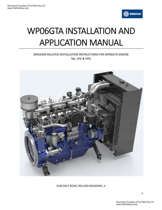
WP06GTA INSTALLATION AND
APPLICATION MANUAL
 
EMISSION‐RELATED INSTALLATION INSTRUCTIONS FOR WP06GTA ENGINE 
NG, LPG & VPG 


3100 GOLF ROAD, ROLLING MEADOWS, IL 
   
Document Courtesy of Fly Parts Guy Co.
www.FlyPartsGuy.com
Document Courtesy of Fly Parts Guy Co.
www.FlyPartsGuy.com
                                                                                                                                                                                                  
1 
 
Contents 
INSTALLATION OF CERTIFIED ENGINES .................................................................................... 1 
NOTICE OF IMPORTANT REQUIREMENTS OF CERTIFIED ENGINES 
.......................................... 3 
SYSTEM OVERVIEW .................................................................................................................. 4 
ENGINE MOUNTING SUSPENSION ......................................................................................... 10 
ELECTRICAL SYSTEM ............................................................................................................... 11 
INTAKE AIR SYSTEM ............................................................................................................... 13 
CLOSED CRANKCASE VENTILATION 
........................................................................................ 14 
NATURAL GAS FUEL SYSTEM 
.................................................................................................. 15 
LPG & NG BI‐FUEL SYSTEM .................................................................................................... 16 
VPG SINGLE FUEL SYSTEM ..................................................................................................... 16 
COOLING SYSTEM .................................................................................................................. 16 
PRE‐CATALYST OXYGEN SENSOR ........................................................................................... 17 
POST‐CATALYST OXYGEN SENSOR ......................................................................................... 17 
CATALYTIC CONVERTER ......................................................................................................... 20 
FLYWHEEL .............................................................................................................................. 22 
ADJUSTABLE PARAMETERS .................................................................................................... 23 
FUEL SYSTEM DIAGNOSTIC .................................................................................................... 23 
ACRONYM DEFINITION .......................................................................................................... 24 
 
   
Document Courtesy of Fly Parts Guy Co.
www.FlyPartsGuy.com
Document Courtesy of Fly Parts Guy Co.
www.FlyPartsGuy.com
                                                                                                                                                                                                  
1 
 
INSTALLATION	OF	CERTIFIED	ENGINES		
Thank you for your recent purchase of an EPA certified WEICHAI Nonroad and Stationary Industrial 
Engine.  
 
These instructions are intended to provide the installer of the engine all the information that is 
necessary to properly install the engine and related components into the equipment chassis. The United 
States Environmental Protection Agency (EPA) requires that the manufacturer of the engine provide 
installation instructions to the equipment manufacturers as defined in the Code of Federal Regulations 
(40CFR 1048.130). 
 
Failing to follow these instructions when installing a certified engine in a piece of nonroad equipment 
violates federal law (40 CFR 1068.105(b)), subject to fines or other penalties as described in the Clean 
Air Act. 
 
This engine is certified to be used in nonroad and stationary constant speed only equipment 
applications.  Do not install this engine for use in any variable speed applications! 
 
This industrial engine comes fully equipped and certified with a complete emissions control system 
which includes the fuel system, sensors and actuators, a fully integrated engine management system, 
and an exhaust after treatment system including a three‐way catalyst. When this industrial engine is 
correctly installed by an Original Equipment Manufacturer (OEM), it will meet or exceed the Emission 
Standards for Large Spark Ignited (LSI) engines established by the US Environmental Protection Agency 
(EPA). This engine has been certified to exhaust emission standards in 40 CFR Part 1048 and 40 CFR Part 
60 JJJJ including appropriate deterioration factors, over the regulated useful lifetime of seven years or 
5000 hours, whichever occurs first. 
 
Emissions compliance throughout the useful lifetime requires proper engine maintenance. Please refer 
to the maintenance schedule in the service manual for details.   
Document Courtesy of Fly Parts Guy Co.
www.FlyPartsGuy.com
Document Courtesy of Fly Parts Guy Co.
www.FlyPartsGuy.com
                                                                                                                                                                                                  
3 
 
NOTICE	OF	IMPORTANT	REQUIREMENTS	OF	CERTIFIED	ENGINES		
Important Notice‐ The required Emissions Control Information label has been placed on this certified 
engine during the WEICHAI assembly process.  If you install the engine in a way that makes the engine's 
emission control information label hard to read during normal engine maintenance, you must place a 
duplicate label on the equipment, as described in 40 CFR 1068.105. Contact Weichai to request a 
duplicate label (Dial 1‐855‐922‐9001). 
 
Important Notice‐ This engine uses a crankcase recirculation system that routes all crankcase gasses 
back to the engine intake air system. The EPA requires every certified industrial engine to have a closed 
crankcase and no crankcase emissions may be vented to the atmosphere as described in the Code of 
Federal Regulations (40 CFR 1048.115). Please refer to the Intake Air System section included in these 
instructions for details. 
 
Important Notice‐ To meet EPA exhaust emissions field testing requirements it is important that the 
OEM design the exhaust system so that a 20‐centimeter extension can be temporarily installed on the 
equipment’s exhaust outlet. The extension is required in order to prevent dilution of the exhaust sample 
with ambient air during the exhaust emissions test. 
 
Important Notice‐ EPA requires that WEICHAI warranty all emission‐related components as defined in 
40 CFR Part 1048.120. Please refer to the Emission Related Warranty Statement included with the sale 
of all new engines for further details. Warranty for non‐critical emissions components will be as defined 
in the individual purchase agreement. 
 
   
Document Courtesy of Fly Parts Guy Co.
www.FlyPartsGuy.com
Document Courtesy of Fly Parts Guy Co.
www.FlyPartsGuy.com
                                                                                                                                                                                                  
4 
 
SYSTEM	OVERVIEW	
STOICHIOMETRIC, RICH BURN CONTROL 
The 4G engine control module is the backbone of the EControls control system.  Proven in a multitude of 
applications around the world, the 4G based engine control system delivers reliable operation and 
optimal engine operation no matter the environment. The 4G engine control system for highly regulated 
emission countries enables operation at the stoichiometric air / fuel ratio with Rich Burn and a 3 Way 
Catalyst.  Stoichiometric engine operation ensures that there is the precise amount of air delivered to 
completely burn all the fuel. The stoichiometric Air Fuel Ratio (AFR) for natural gas is 17.2:1 and for 
propane is 15.5:1. With rich burn there is slightly less air delivered relative to fuel resulting in slightly 
less fuel efficiency, more power and a cooler combustion process.  Figure 1 shows the required 4G 
engine control system configurations for Propane (VPG), Natural Gas (NG) and Bi‐Fuel (VPG and NG) 
with the TWC.   
 
 
Figure 1 WP06GTA Schematic 
 
Bi‐FUEL 
The 4G Engine Controls System has full engine software control authority, therefore switching from 
Natural Gas (NG) to Propane (LPG/VPG) fuel is a software command from the operator console or a 
switch input into the 4G ECM.  The Weichai WP06GNA engine is capable of operating in bi‐fuel mode 
starting from VPG/LPG and switching to NG after the NG pressure develops from operation.  With the 
proper valve and sensor arrangement the fuel supply transition can be made while in operation, under 
full load, and automatically.  
Document Courtesy of Fly Parts Guy Co.
www.FlyPartsGuy.com
Document Courtesy of Fly Parts Guy Co.
www.FlyPartsGuy.com
                                                                                                                                                                                                  
5 
 
NG/VPG is WP06GTA standard configuration. With an add‐on option, WP06GTA can also support LPG, 
manual or automatic switching. 
TELEMATICS SUPPORT 
Hardware and software capability exist in the full authority 4G control system to send and receive CAN 
communication files in a structured message format. The input and output file structure and variable 
content need to be defined by the customer and implemented by WEICHAI.  There will be an 
engineering change associated with setting up the file structures and debugging the communications 
with the telematics module. Equipment and technical support is available from Weichai. 
Diagnostic Messages 
The 4G engine control system contains a highly configurable diagnostic list that can be tailored to each 
application’s specific needs using the calibration spreadsheet. With each available P‐code listed along 
with the short‐name description. Note that not all DTCs necessarily apply to every application.   
 
ECM: Engine Control Module: 4G 90 pin  
The ECM is full authority, by this we mean it includes the ignition and air/fuel ratio control, contains all 
the I/O to interface the engine with the application and has a complete set of diagnostics.  By 
implementing all functions in one box the overall system complexity is reduced as is the total system 
cost. 
Some of features included in the ECMs are lean burn or stoichiometric combustion control, continuous 
fuel injection control or standard digital injectors, ignition control electronic boost control for 
turbochargers – VGT or wastegate, drive‐by‐wire throttle control, oxygen sensor based closed‐loop 
air/fuel ratio control (wide band (UEGOs) or switching (HEGOs)), adaptive spark and fuel control, EGR 
control, transmission / engine coordination, speed control/governing (idle, max speed, all‐speed, cruise 
control) and vehicle network interface systems (CAN, J1708, J1850, Ford SCP). 
DEPR: Direct Acting Electronic Pressure Regulator 
 
Our fuel control device is referred to as a Direct Acting Electronic Pressure Regulator or D‐EPR shown in 
Figure 2. Its benefits to our customers and the end customer are: 
Document Courtesy of Fly Parts Guy Co.
www.FlyPartsGuy.com
Document Courtesy of Fly Parts Guy Co.
www.FlyPartsGuy.com
                                                                                                                                                                                                  
6 
 
 
Figure 2 Direct Acting Electronic Pressure Regulator (DEPR) 
 
- It is a continuous fuel flow device.  This allows the most homogeneous mixture of air and fuel to the 
engine yielding optimum combustion with minimum emissions and maximum fuel economy. 
- It operates on low pressure fuel from 6 to 20 inches of water of inlet pressure, no pressure 
intensification system required. 
- It does not wear in the case or dry fuels (NG) and it does not stick or clog due to heavy hydrocarbons 
or waxes found in LPG. 
- It is fast and accurate, providing precise air/flow ratio control during transients (or load acceptance). 
The DEPR is a single‐stage microprocessor based electromechanical fuel pressure regulator that 
incorporates a high‐speed actuator.  It communicates with the Engine Control Module (ECM) over a 
Controller Area Network (CAN) link, receiving fuel pressure commands and broadcasting DEPR operating 
parameters back to the ECM.  The DEPR can regulate fuel pressure between +/‐ 17 inches of water 
column above the Mixer air inlet pressure, providing sufficient control authority to stall an engine either 
rich or lean.  When the DEPR receives an output pressure command from the ECM, the valve is internally 
driven to attain targeted fuel pressure, the DEPR then closes the loop internally using a built‐in fuel 
pressure sensor to maintain target fuel pressure/fuel flow rate, until another external command from 
the ECM is received.   
Document Courtesy of Fly Parts Guy Co.
www.FlyPartsGuy.com
Document Courtesy of Fly Parts Guy Co.
www.FlyPartsGuy.com
                                                                                                                                                                                                  
7 
 
 
Figure 3 E480 Mixer 
 
MIXER: E480  
 
A relatively constant pressure drop mixer is used to draw fuel when coupled with EPR. The basic 
principle of the product is to introduce air and fuel into engine. It also aids in introducing turbulence into 
the air and fuel assisting in making it a homogeneous mixture. The mixer also acts to increase or 
decrease the fuel entering the engine proportional to the amount of air flowing in the engine on a 
volumetric basis. 
E480 MIXER provide the following benefits to the market: 
- Superior fuel/air (phi) ratio accuracy 
- Reduced part to part fuel/air ratio repeatability 
- Extended diaphragm life through material selection and design 
- Performance over the ‐40C to +125C temperature range 
- Eliminate LPG fuel contamination issues 
- Superior low flow resolution and repeatability, eliminates idle adjustment 
Document Courtesy of Fly Parts Guy Co.
www.FlyPartsGuy.com
Document Courtesy of Fly Parts Guy Co.
www.FlyPartsGuy.com
                                                                                                                                                                                                  
8 
 
HEAVY‐DUTY DUAL STAGE REGULATOR (DSR)  
The heavy‐duty dual stage regulator vaporizes liquid propane to gaseous form and regulates the fuel 
pressure to meet the fuel pressure requirement. 
 
Figure 4 Heavy‐Duty Dual Stage Regulator 
 
The HD DSR is a two stage fully mechanical regulator that is available in LPG configurations. The DSR is 
normally open with a positive outlet pressure and must be used with fuel lock‐off upstream to prevent 
fuel flow when the engine is not cranking or running. The HD DSR is connected to the DEPR, by a low 
pressure flexible hose. It also has a reference port that is connected to the fuel / air mixer for turbo‐
charged applications. 
Key features of the HD Dual Stage Regulator are: 
- Full mechanical pressure regulation 
- Can be engine or chassis mounted (vibration requirements are defined on the installation drawing) 
- Flows 250 kW at the rate inlet pressure 
- 1725 kPa inlet regulated down to a 3.5 kPa outlet pressure 
 
TURBOCHARGER 
The turbocharger provides the air‐fuel mixture at the optimal pressure level to the engine in order to 
generate the right power. Along with turbocharger, a by‐pass valve controls the boost level required for 
the rated speed and engine load. The turbocharger not only provides the boost pressure for higher 
power output but also acts as a secondary mixer for air‐fuel mixture.  
 
Figure 5 Turbocharger    
Document Courtesy of Fly Parts Guy Co.
www.FlyPartsGuy.com
Document Courtesy of Fly Parts Guy Co.
www.FlyPartsGuy.com
                                                                                                                                                                                                  
9 
 
BOOST RECIRCULATION VALVE (BRV) 
The Boost Recirculation Valve is a piston‐actuated high flow pressure recirculation valve system. It is 
designed to reduce or eliminate intake system pressure spikes between the throttle plate and the 
turbocharger, which in turn minimizes wear and fatigue on turbocharger components. This is a 
normally‐closed valve which is actuated by differences in throttle inlet pressure (TIP), compressor inlet 
pressure (CIP) and manifold absolute pressure (MAP). The MAP connection is the reference pressure 
used to actuate the BRV.  
Key features of the BRV are: 
- Reduces/eliminates turbocharger compressor stall/surge 
- Increase turbocharger life 
- Flow is bi‐directional through the MAP reference 
 
 
Figure 6 Boost Recirculation Valve (BRV) 


Document Courtesy of Fly Parts Guy Co.
www.FlyPartsGuy.com
Document Courtesy of Fly Parts Guy Co.
www.FlyPartsGuy.com
                                                                                                                                                                                                  
10 
 
ENGINE	MOUNTING	SUSPENSION	
Maximum inclination angles 
Maximum inclination angles at which the engine will operate satisfactorily: 
- Transverse inclination, intake  10deg 
- Transverse inclination, exhaust  10deg 
- Longitudinal inclination, front  5deg 
- Longitudinal inclination, back  5deg 
 
Engine General Dimension 
 
Figure 7 Engine General Dimensions and Layout 
	
  	
Document Courtesy of Fly Parts Guy Co.
www.FlyPartsGuy.com
Document Courtesy of Fly Parts Guy Co.
www.FlyPartsGuy.com
                                                                                                                                                                                                  
11 
 
ELECTRICAL	SYSTEM	
WIRE HARNESS DIAGRAM 


Figure 8 Wire Harness Diagram 
   
Document Courtesy of Fly Parts Guy Co.
www.FlyPartsGuy.com
Document Courtesy of Fly Parts Guy Co.
www.FlyPartsGuy.com
                                                                                                                                                                                                  
12 
 
CONTROL PANEL:  
Optional: PV380 AND RELATED HARNESS, Murphy MPC10, MPC20, and additional panel options are 
available. Contact Weichai for details. 
 
 
Figure 9 PV380 & Related Harness 
 
BATTERY SETUP  
One 12V battery is used to provide 12V to the control system. The batteries need to be setup according 
to the steps below: 
- Engine Electrical System is 12‐volt DC Negative Ground 
- The Engine Battery should be 650CCA or Greater. Never disconnect the battery when running. The 
batteries should be attached to the engine at all times. 
- Connect positive (+) red wire to positive (+) terminal on battery. 
- Connect negative (‐) black wire to negative (‐) terminal on battery. 
Document Courtesy of Fly Parts Guy Co.
www.FlyPartsGuy.com
Document Courtesy of Fly Parts Guy Co.
www.FlyPartsGuy.com
                                                                                                                                                                                                  
13 
 
CAN BUS J1939 INTERFACE CONNECTING WITH ZTR TELEMATICS 
 
 
Figure 10 CAN BUS J1939 Interface Connection with ZTR Telematics 
	
INTAKE	AIR	SYSTEM	
The intake system should be sealed between the mixer inlet and the filter. Proper clamps should be 
used to ensure unfiltered air is not drawn into the system. Use piping with minimum diameter equal to 
mixer inlet. When in an enclosure, it can sometimes be necessary to use an externally mounted filter. It 
can be beneficial to engine life and performance to draw in air from the coolest location possible. 
Document Courtesy of Fly Parts Guy Co.
www.FlyPartsGuy.com
Document Courtesy of Fly Parts Guy Co.
www.FlyPartsGuy.com
                                                                                                                                                                                                  
14 
 
 
Figure 11 Intake Air System 
 
 
CLOSED	CRANKCASE	VENTILATION	
Weichai engine uses a closed crankcase system as shown in Figure 12. The breather separates the 
crankcase oil/gas mixture and lets the oil return to the sump and sends the gas into the intake system. 
Document Courtesy of Fly Parts Guy Co.
www.FlyPartsGuy.com
Document Courtesy of Fly Parts Guy Co.
www.FlyPartsGuy.com
                                                                                                                                                                                                  
15 
 
 
Figure 12 Closed Crankcase Ventilation System 
 
NATURAL	GAS	FUEL	SYSTEM	
The fuel first passes the fuel shut off when the engine starts cranking. Then it goes through the DEPR 
and comes into the mixer to be mixed with the air from the air filter as shown in Figure 13.  


Figure 13 Natural Gas/Wellhead Gas Fuel System 
Document Courtesy of Fly Parts Guy Co.
www.FlyPartsGuy.com
Document Courtesy of Fly Parts Guy Co.
www.FlyPartsGuy.com
                                                                                                                                                                                                  
16 
 
 
LPG	&	NG	BI‐FUEL	SYSTEM	
When the engine operates with LPG, the NG shutoff valve will be closed. The LPG first enters the LPG 
shutoff valve and then goes to LPG evaporator to turn the LPG to vapor and later enters the DEPR and 
further mixes with the air in the mixer as shown in Figure 14.  
 
Figure 14 LPG & NG Bi‐Fuel System 
 
	
VPG	SINGLE	FUEL	SYSTEM	
For single VPG fuel application, the same shut‐off valve as NG is used to turn on or off the fuel, but the 
shut‐off valve needs to be connected with the secondary fuel connector from the harness as Secondary 
Lock‐off (LPG) only.  
 
 
COOLING	SYSTEM	
Figure 15 shows the configuration of the cooling system. Please refer to Figure 7 for the 2D dimensions 
of the cooling system installed with the engine and skid. 


Document Courtesy of Fly Parts Guy Co.
www.FlyPartsGuy.com
Document Courtesy of Fly Parts Guy Co.
www.FlyPartsGuy.com
                                                                                                                                                                                                  
17 


Figure 15 Cooling System 
 
PRE‐CATALYST	OXYGEN	SENSOR	
Apply an adequate amount of anti‐seize compound to the threads of the oxygen sensor and install the 
sensor in the O2 sensor port located on the exhaust manifold elbow pipe. Tighten the sensor to the 
specified torque 29.5ft‐lb ~44ft‐lb (40Nm~60Nm).  Anti‐seize on thread only, don’t put on the sensor. 
 
POST‐CATALYST	OXYGEN	SENSOR	
The sensor installation point must be sufficiently tested by the customer for functionality and durability. 
There shall be no possibility of exhaust leaks upstream of the sensor as exhaust pulsations can draw in 
ambient air leading to erroneous measurements.  
 
Installation in the exhaust line must be at a point guaranteeing representative exhaust gas composition 
while also satisfying the specified temperature limits. The active sensor ceramic element heats up 
quickly. This means that the sensor installation location must be selected to minimize exhaust‐side 
Document Courtesy of Fly Parts Guy Co.
www.FlyPartsGuy.com
Document Courtesy of Fly Parts Guy Co.
www.FlyPartsGuy.com
                                                                                                                                                                                                  
18 
 
stressing with condensation water in order to prevent ceramic element cracking. This is helped by 
locating the sensor on the outlet of the catalyst assembly.  
 
Design measures: 
- Locate sensor as close to the catalytic converter outlet as possible, without exceeding maximum 
allowed temperature range  
- Attempt to achieve rapid heating‐up of the exhaust pipes in the area in front of the sensor. 
The exhaust pipe in front of the sensor should not contain any pockets, projections, protruding or 
edges etc. to avoid accumulation of condensation water. A downside slope of the pipe is 
recommended. 
- The use of a sensor type with double protection tube can give a better protection of the sensor 
ceramic against condensation water drops. In this case make sure, that the front hole of the double 
protection tube does not point against exhaust gas stream. 
 
 
Figure 16 UEGO Sensor Installation 
 
 
Document Courtesy of Fly Parts Guy Co.
www.FlyPartsGuy.com
Document Courtesy of Fly Parts Guy Co.
www.FlyPartsGuy.com
                                                                                                                                                                                                  
19 
 
System measures: 
- Never switch on sensor heating before engine starting. 
- Delayed switch‐on or power control of the sensor heater (e.g. as a function of engine and ambient 
temperature), so that the max. allowed ceramic temperature is not exceeded when there is 
condensation water present. 
 
Installation angle should be inclined at least 10° towards horizontal (electrical connection upwards), thus 
preventing the collection of liquids between sensor housing and sensor element during the cold start 
phase. Other installation angles must be inspected and tested individually. 
 
Avoid inadmissible heating up of the sensor cable grommet, particularly when the engine has been 
switched off after running under max. load conditions. The use of cleaning/greasing fluids or 
evaporating solids at the sensor plug connection is not permitted. Assemble with high temperature 
resistant grease on the screw‐in thread. Tightening torque: 29.5ft‐lb ‐ 44ft‐lb (40Nm ‐ 60Nm). Material 
characteristics and strength of the thread must be appropriate. Recommended material for the thread 
boss in the exhaust pipe is temperature resistant stainless ferritic steel, e.g. X 5 CrNi 18 9, DIN 17440 
1.4301 or 1.4303 or SAE 30304 or SAE 30305 (US standard)  
 
The sensor’s protection tube must protrude completely into the exhaust‐gas flow.  


Figure 17 TWC and Post HEGO Sensor Installation 
 
There is to be no possibility of the sensor protection tube contacting the opposite side of the exhaust 
pipe. A waterproof electrical connector’s version is required.  
 
The sensor must not be exposed to strong mechanical shocks (e.g. while the sensor is installed). 
Otherwise the sensor element may crack without visible damage at the sensor housing.  
 
For physical reasons the sensor needs ambient air at its reference gas side. Replacement of the air 
volume inside the sensor must be guaranteed by a sufficient air permeability of the wires and the 
Document Courtesy of Fly Parts Guy Co.
www.FlyPartsGuy.com
Document Courtesy of Fly Parts Guy Co.
www.FlyPartsGuy.com
                                                                                                                                                                                                  
20 
 
connectors between sensor and ECU. The breathability should be higher than 1 ml/minute at a test 
pressure of 100mbar.  
 
Underfloor installation of the sensor remote from the engine requires an additional check of the 
following points: 
- Positioning of the sensor with respect to stone impact hazard. 
- Positioning and fixing of cable and connector with respect to mechanical damage, cable bending 
stress and thermal stress. 
 
The sensor cable must be routed so that it is free of bends, mechanical tension, and chafing points 
considering the movement of the exhaust system in relation to the vehicle body. The cable and 
connector should not be subjected to excessive temperatures that could cause damage. 


Additional instructions for the installation downstream the catalytic converter 
- Between catalyst and sensor location absolute gas tightness of the exhaust system must be ensured. 
- When the sensor is installed in the exhaust pipe there should be no detachable connections 
between catalytic converter and sensor (e.g. flange, clamp‐screw joint). 
- In order to protect the active sensor ceramic against condensation water from the exhaust gas side 
the sensor heater voltage must be power controlled after cold start of the engine. During the 
condensation water phase, the ceramic temperature should be kept at approx. 302degF ~572degF 
(150°C‐300°C). The corresponding control parameter must be determined according to application. 
- The sensor should be mounted as close to the outlet of the catalytic converter as possible without 
exceeding sensor maximum temperatures. 
- The sensor should be mounted as far from the exhaust pipe outlet as possible to avoid dilution from 
ambient air. Minimum distance between sensor and exhaust outlet should be 15.7 inches (400 mm). 
 
CATALYTIC	CONVERTER	
A very important component in a low emission engine is the catalytic converter. Weichai Engines use a 
TWC converter. For this type of catalytic converter to work properly, the following two criteria must be 
met: 
- The air‐to‐fuel ratio must oscillate between rich and lean.  
- The catalyst substrate (also known as a “brick,” located inside the converter shell) must be kept hot. 
 
Strict compliance with these provisions, conditions, and operating limits for catalytic converters must be 
maintained. If these parameters cannot be met or are not known, additional engineering and validation 
are required. 
 
Operation 
- The continuous operating exhaust gas temperature must be between 1112degF (600°C) and 
1562degF (850°C).  
Document Courtesy of Fly Parts Guy Co.
www.FlyPartsGuy.com
Document Courtesy of Fly Parts Guy Co.
www.FlyPartsGuy.com
                                                                                                                                                                                                  
21 
 
- The product installer shall take necessary precautions to accommodate shell skin temperatures up 
to 1202degF (650°C). 
- System backpressure must remain with +/‐ 5% of nominal conditions. 
- Engine misfires and exhaust stream containments are not permissible. 
 
Vibration 
- Vibration isolation must be provided between the engine and the TWC. 
- Vibration isolation must be provided between the product and the chassis. 
- Vibration acceleration loads shall not exceed 10g. 
 
Installation  
- Product shall not support mounting loads from adjacent components. 
- Product must be mounted within +/‐ 10° of horizontal. Any other orientation must be approved by 
the WEICHAI. 
- Product must be supported at a minimum of two mounting locations. 
- Installer shall ensure mounting hardware, such as fasteners, is sufficient for the application. 
- WEICHAI recommends use of graphite gaskets for flanged joints. 
- Heat shields must be reviewed by the manufacturer. 
- Product cannot be used in corrosive environments (i.e. salt water). 
 
Mounting the catalytic converter in the proper location will control the substrate temperature. To 
quickly heat up the catalyst and to ensure an effective operating temperature, the center of the 
substrate must be located a minimum of 30 inches (762mm) downstream of the exhaust manifold 
flange. This measurement is made along the length of the exhaust pipe and must take all bends and 
curves into consideration. The max distance allowed downstream of the exhaust manifold flange is 
36inches (914mm).  Figure 18 depicts an example of catalytic converter setup. 
   
Figure 18 Catalytic Converter Orientation 
 
Document Courtesy of Fly Parts Guy Co.
www.FlyPartsGuy.com
Document Courtesy of Fly Parts Guy Co.
www.FlyPartsGuy.com
                                                                                                                                                                                                  
22 
 
Figure 19 depicts an example of catalytic mounting options 
 
 
Figure 19 Catalytic Converter Mounting Options 
FLYWHEEL	
All Weichai engines come with SAE 1 standard flywheel with SAE 3 adapters. The adapter will be used 
depending on the customer requirement and the adapters are as shown in below picture. Contact 
Weichai representative for assistance of the connector/adaptor installation. 
 
Figure 20 Flywheel and Flywheel housing 
 
Document Courtesy of Fly Parts Guy Co.
www.FlyPartsGuy.com
Document Courtesy of Fly Parts Guy Co.
www.FlyPartsGuy.com
                                                                                                                                                                                                  
23 
 
 
ADJUSTABLE	PARAMETERS		
This engine has been certified by the US EPA to operate on pipeline quality commercial Natural Gas fuel 
as well as commercial LPG/propane. 
 
The Fuel System is non‐adjustable and it can compensate for changes within commercial fuels at 
different locations in the US.  Customers can use a fuel switch (PG Switch illustration in Figure 21) to 
switch between NG and LPG operation. The default setting is for NG, the other position “PG” is for fuels 
with LPG/VPG (short Engine Interface Pin G & R). 
 
 
Figure 21 Fuel Switch for Different Fuel BTU Ranges 


WARNING: ADJUSTMENTS MADE TO THE FUEL DELIVERY SYSTEM WILL INFLUENCE THE TAILPIPE 
EXHAUST EMISSIONS. IT IS THE OWNER/OPERATOR’S RESPONSIBILITY TO TEST THE SPECIFIC FUEL TYPE 
AT EACH SITE OF INSTALLATION AND DETERMINE THE CORRECT FUEL SYSTEM SETTINGS. 
 
 
Fuel Pressure 
Fuel Pressure need to be checked for the first start as in the Table 1 
 
Table 1 EPR inlet pressure specification 
Maximum EPR Rated Pressure  kPa  6.9 
Maximum Running pressure to Electronic Pressure Regulator (EPR)  kPa  2.7 
        
 
FUEL	SYSTEM	DIAGNOSTIC	
FUEL SYSTEM DESCRIPTION 
The Engine Control Module (ECM) receives information from various engine sensors in order to control 
the operation of the Integrated Electronic Pressure Regulator (EPR) and Shut‐Off Valve. The Shut‐Off 
Valve solenoid prevents fuel flow unless the engine is cranking or running. 
 
At Key ON, the DEPR valve receives a two (2) second prime pulse from the ECM, allowing time 
for the fuel to flow through the fuel filter and fuel lines to the IEPR. 
Document Courtesy of Fly Parts Guy Co.
www.FlyPartsGuy.com
Document Courtesy of Fly Parts Guy Co.
www.FlyPartsGuy.com
                                                                                                                                                                                                  
24 
 
 
The fuel is then to the mixer. Engine cranking generates vacuum which provided lift for the mixer air 
valve and is commonly referred to as air valve vacuum. Once in the mixer, the fuel is combined with air 
and is drawn into the engine for combustion. 
 
 
ACRONYM	DEFINITION	
 
ABBREVIATION  DEFINITION 
DEPR  Direct acting Electronic Pressure Regulator 
DSR  Dual Stage Regulator 
DST  Diagnostic Service Tool 
ECM  Engine Control Module 
LPG  Liquid Propane Gas 
NG  Natural Gas 
TWC  Three Way Catalyst 
VPG  Vapor Propane Gas 
   
 
Document Courtesy of Fly Parts Guy Co.
www.FlyPartsGuy.com
Document Courtesy of Fly Parts Guy Co.
www.FlyPartsGuy.com

More Related Content

Similar to 6 ta application - mar 2019

6.0 l dies
6.0 l dies6.0 l dies
6.0 l dies
rukford
 
6.0 l dies
6.0 l dies6.0 l dies
6.0 l dies
rukford
 
CASE IH AXIAL-FLOW 8230 Tier 4 Combine Service Repair Manual.pdf
CASE IH AXIAL-FLOW 8230 Tier 4 Combine Service Repair Manual.pdfCASE IH AXIAL-FLOW 8230 Tier 4 Combine Service Repair Manual.pdf
CASE IH AXIAL-FLOW 8230 Tier 4 Combine Service Repair Manual.pdf
f8skjdkdmdmd
 
CASE IH AXIAL-FLOW 8230 Tier 4 Combine Service Repair Manual.pdf
CASE IH AXIAL-FLOW 8230 Tier 4 Combine Service Repair Manual.pdfCASE IH AXIAL-FLOW 8230 Tier 4 Combine Service Repair Manual.pdf
CASE IH AXIAL-FLOW 8230 Tier 4 Combine Service Repair Manual.pdf
8dusjkdmmdmd
 

Similar to 6 ta application - mar 2019 (20)

13 ta assembly & disassembly - flypartsguy.com - 1.2018
13 ta   assembly & disassembly - flypartsguy.com - 1.201813 ta   assembly & disassembly - flypartsguy.com - 1.2018
13 ta assembly & disassembly - flypartsguy.com - 1.2018
 
6.0 l dies
6.0 l dies6.0 l dies
6.0 l dies
 
6.0 l dies
6.0 l dies6.0 l dies
6.0 l dies
 
13 ta parts - flypartsguy.com - 3.2019
13 ta   parts - flypartsguy.com - 3.201913 ta   parts - flypartsguy.com - 3.2019
13 ta parts - flypartsguy.com - 3.2019
 
10 ta parts - flypartsguy.com - 4.2019
10 ta   parts - flypartsguy.com - 4.201910 ta   parts - flypartsguy.com - 4.2019
10 ta parts - flypartsguy.com - 4.2019
 
10 na parts - flypartsguy.com - 3.2019
10 na   parts - flypartsguy.com - 3.201910 na   parts - flypartsguy.com - 3.2019
10 na parts - flypartsguy.com - 3.2019
 
maxxforce-7-manual.pdf
maxxforce-7-manual.pdfmaxxforce-7-manual.pdf
maxxforce-7-manual.pdf
 
13 ta application - flypartsguy.com - mar 2019
13 ta   application - flypartsguy.com - mar 201913 ta   application - flypartsguy.com - mar 2019
13 ta application - flypartsguy.com - mar 2019
 
6 ta parts - flypartsguy.com - 3.2019
6 ta   parts - flypartsguy.com - 3.20196 ta   parts - flypartsguy.com - 3.2019
6 ta parts - flypartsguy.com - 3.2019
 
6 l operation and maintenance - flypartsguy.com - 8.2019
6 l   operation and maintenance - flypartsguy.com - 8.20196 l   operation and maintenance - flypartsguy.com - 8.2019
6 l operation and maintenance - flypartsguy.com - 8.2019
 
6 na assembly & disassembly - flypartsguy.com - 8.2019
6 na   assembly & disassembly - flypartsguy.com - 8.20196 na   assembly & disassembly - flypartsguy.com - 8.2019
6 na assembly & disassembly - flypartsguy.com - 8.2019
 
6 l operation and maintenance - flypartsguy.com - 8.2019
6 l   operation and maintenance - flypartsguy.com - 8.20196 l   operation and maintenance - flypartsguy.com - 8.2019
6 l operation and maintenance - flypartsguy.com - 8.2019
 
CASE IH AXIAL-FLOW 8230 Tier 4 Combine Service Repair Manual.pdf
CASE IH AXIAL-FLOW 8230 Tier 4 Combine Service Repair Manual.pdfCASE IH AXIAL-FLOW 8230 Tier 4 Combine Service Repair Manual.pdf
CASE IH AXIAL-FLOW 8230 Tier 4 Combine Service Repair Manual.pdf
 
CASE IH AXIAL-FLOW 8230 Tier 4 Combine Service Repair Manual.pdf
CASE IH AXIAL-FLOW 8230 Tier 4 Combine Service Repair Manual.pdfCASE IH AXIAL-FLOW 8230 Tier 4 Combine Service Repair Manual.pdf
CASE IH AXIAL-FLOW 8230 Tier 4 Combine Service Repair Manual.pdf
 
CASE IH AXIAL-FLOW 9230 Tier 4 Combine Service Repair Manual.pdf
CASE IH AXIAL-FLOW 9230 Tier 4 Combine Service Repair Manual.pdfCASE IH AXIAL-FLOW 9230 Tier 4 Combine Service Repair Manual.pdf
CASE IH AXIAL-FLOW 9230 Tier 4 Combine Service Repair Manual.pdf
 
CASE IH AXIAL-FLOW 9230 Tier 4 Combine Service Repair Manual.pdf
CASE IH AXIAL-FLOW 9230 Tier 4 Combine Service Repair Manual.pdfCASE IH AXIAL-FLOW 9230 Tier 4 Combine Service Repair Manual.pdf
CASE IH AXIAL-FLOW 9230 Tier 4 Combine Service Repair Manual.pdf
 
CASE IH AXIAL-FLOW 8230 Tier 4 Combine Service Repair Manual.pdf
CASE IH AXIAL-FLOW 8230 Tier 4 Combine Service Repair Manual.pdfCASE IH AXIAL-FLOW 8230 Tier 4 Combine Service Repair Manual.pdf
CASE IH AXIAL-FLOW 8230 Tier 4 Combine Service Repair Manual.pdf
 
CASE IH AXIAL-FLOW 7230 Tier 4 Combine Service Repair Manual.pdf
CASE IH AXIAL-FLOW 7230 Tier 4 Combine Service Repair Manual.pdfCASE IH AXIAL-FLOW 7230 Tier 4 Combine Service Repair Manual.pdf
CASE IH AXIAL-FLOW 7230 Tier 4 Combine Service Repair Manual.pdf
 
CASE IH AXIAL-FLOW 7230 Tier 4 Combine Service Repair Manual.pdf
CASE IH AXIAL-FLOW 7230 Tier 4 Combine Service Repair Manual.pdfCASE IH AXIAL-FLOW 7230 Tier 4 Combine Service Repair Manual.pdf
CASE IH AXIAL-FLOW 7230 Tier 4 Combine Service Repair Manual.pdf
 
CASE IH AXIAL-FLOW 9230 Tier 4 Combine Service Repair Manual.pdf
CASE IH AXIAL-FLOW 9230 Tier 4 Combine Service Repair Manual.pdfCASE IH AXIAL-FLOW 9230 Tier 4 Combine Service Repair Manual.pdf
CASE IH AXIAL-FLOW 9230 Tier 4 Combine Service Repair Manual.pdf
 

More from FrankEasel

More from FrankEasel (20)

13 ta data sheet - flypartsguy.com - 10.2018
13 ta   data sheet - flypartsguy.com - 10.201813 ta   data sheet - flypartsguy.com - 10.2018
13 ta data sheet - flypartsguy.com - 10.2018
 
13 ta brochure - flypartsguy.com - mar 2019
13 ta   brochure - flypartsguy.com - mar 201913 ta   brochure - flypartsguy.com - mar 2019
13 ta brochure - flypartsguy.com - mar 2019
 
13 l operation - flypartsguy.com - 10.2018
13 l   operation - flypartsguy.com - 10.201813 l   operation - flypartsguy.com - 10.2018
13 l operation - flypartsguy.com - 10.2018
 
10 ta data sheet - flypartsguy.com - 8.2018
10 ta   data sheet - flypartsguy.com - 8.201810 ta   data sheet - flypartsguy.com - 8.2018
10 ta data sheet - flypartsguy.com - 8.2018
 
10 ta brochure - flypartsguy.com - 8.2019
10 ta   brochure - flypartsguy.com - 8.201910 ta   brochure - flypartsguy.com - 8.2019
10 ta brochure - flypartsguy.com - 8.2019
 
10 ta assembly & disassembly - flypartsguy.com - 4.2018
10 ta   assembly & disassembly - flypartsguy.com - 4.201810 ta   assembly & disassembly - flypartsguy.com - 4.2018
10 ta assembly & disassembly - flypartsguy.com - 4.2018
 
10 ta application - flypartsguy.com - 4.2017
10 ta   application - flypartsguy.com - 4.201710 ta   application - flypartsguy.com - 4.2017
10 ta application - flypartsguy.com - 4.2017
 
10 l operation and maintenance - oct 2018
10 l   operation and maintenance - oct 201810 l   operation and maintenance - oct 2018
10 l operation and maintenance - oct 2018
 
10 na wiring diagram - flypartsguy.com
10 na   wiring diagram - flypartsguy.com10 na   wiring diagram - flypartsguy.com
10 na wiring diagram - flypartsguy.com
 
10 na training - flypartsguy - 8.2018
10 na   training - flypartsguy - 8.201810 na   training - flypartsguy - 8.2018
10 na training - flypartsguy - 8.2018
 
10 na data sheet - flypartsguy.com - 9.2018
10 na   data sheet - flypartsguy.com - 9.201810 na   data sheet - flypartsguy.com - 9.2018
10 na data sheet - flypartsguy.com - 9.2018
 
10 na brochure - flypartsguy.com - 10.2018
10 na   brochure - flypartsguy.com - 10.201810 na   brochure - flypartsguy.com - 10.2018
10 na brochure - flypartsguy.com - 10.2018
 
10 na assembly - flypartsguy 4.2018
10 na   assembly - flypartsguy 4.201810 na   assembly - flypartsguy 4.2018
10 na assembly - flypartsguy 4.2018
 
10 na application - flypartsguy.com - 3.2017
10 na   application - flypartsguy.com - 3.201710 na   application - flypartsguy.com - 3.2017
10 na application - flypartsguy.com - 3.2017
 
10 l operation - flypartsguy.com - 10.2018
10 l   operation - flypartsguy.com - 10.201810 l   operation - flypartsguy.com - 10.2018
10 l operation - flypartsguy.com - 10.2018
 
6 ta wiring diagram - flypartsguy.com
6 ta  wiring diagram - flypartsguy.com6 ta  wiring diagram - flypartsguy.com
6 ta wiring diagram - flypartsguy.com
 
6 ta data sheet - flypartsguy.com - 8.2018
6 ta   data sheet - flypartsguy.com -  8.20186 ta   data sheet - flypartsguy.com -  8.2018
6 ta data sheet - flypartsguy.com - 8.2018
 
6 ta brochure - flypartsguy.com - 5.2019
6 ta   brochure - flypartsguy.com - 5.20196 ta   brochure - flypartsguy.com - 5.2019
6 ta brochure - flypartsguy.com - 5.2019
 
6 ta assembly & disassembly - 2018
6 ta   assembly & disassembly - 20186 ta   assembly & disassembly - 2018
6 ta assembly & disassembly - 2018
 
Wp6 gna wiring diagram - flypartsguy.com
Wp6 gna   wiring diagram - flypartsguy.comWp6 gna   wiring diagram - flypartsguy.com
Wp6 gna wiring diagram - flypartsguy.com
 

Recently uploaded

Vip Mumbai Call Girls Mumbai Call On 9920725232 With Body to body massage wit...
Vip Mumbai Call Girls Mumbai Call On 9920725232 With Body to body massage wit...Vip Mumbai Call Girls Mumbai Call On 9920725232 With Body to body massage wit...
Vip Mumbai Call Girls Mumbai Call On 9920725232 With Body to body massage wit...
amitlee9823
 
Sales & Marketing Alignment_ How to Synergize for Success.pptx.pdf
Sales & Marketing Alignment_ How to Synergize for Success.pptx.pdfSales & Marketing Alignment_ How to Synergize for Success.pptx.pdf
Sales & Marketing Alignment_ How to Synergize for Success.pptx.pdf
Aggregage
 
Tata_Nexon_brochure tata nexon brochure tata
Tata_Nexon_brochure tata nexon brochure tataTata_Nexon_brochure tata nexon brochure tata
Tata_Nexon_brochure tata nexon brochure tata
aritradey27234
 
Escorts Service Rajajinagar ☎ 7737669865☎ Book Your One night Stand (Bangalore)
Escorts Service Rajajinagar ☎ 7737669865☎ Book Your One night Stand (Bangalore)Escorts Service Rajajinagar ☎ 7737669865☎ Book Your One night Stand (Bangalore)
Escorts Service Rajajinagar ☎ 7737669865☎ Book Your One night Stand (Bangalore)
amitlee9823
 
83778-77756 ( HER.SELF ) Brings Call Girls In Laxmi Nagar
83778-77756 ( HER.SELF ) Brings Call Girls In Laxmi Nagar83778-77756 ( HER.SELF ) Brings Call Girls In Laxmi Nagar
83778-77756 ( HER.SELF ) Brings Call Girls In Laxmi Nagar
dollysharma2066
 
+971565801893>>SAFE AND ORIGINAL ABORTION PILLS FOR SALE IN ABUDHABI,DUBAI MA...
+971565801893>>SAFE AND ORIGINAL ABORTION PILLS FOR SALE IN ABUDHABI,DUBAI MA...+971565801893>>SAFE AND ORIGINAL ABORTION PILLS FOR SALE IN ABUDHABI,DUBAI MA...
+971565801893>>SAFE AND ORIGINAL ABORTION PILLS FOR SALE IN ABUDHABI,DUBAI MA...
Health
 
Greenery-Palette Pitch Deck by Slidesgo.pptx
Greenery-Palette Pitch Deck by Slidesgo.pptxGreenery-Palette Pitch Deck by Slidesgo.pptx
Greenery-Palette Pitch Deck by Slidesgo.pptx
zohiiimughal286
 
Rekha Agarkar Escorts Service Kollam ❣️ 7014168258 ❣️ High Cost Unlimited Har...
Rekha Agarkar Escorts Service Kollam ❣️ 7014168258 ❣️ High Cost Unlimited Har...Rekha Agarkar Escorts Service Kollam ❣️ 7014168258 ❣️ High Cost Unlimited Har...
Rekha Agarkar Escorts Service Kollam ❣️ 7014168258 ❣️ High Cost Unlimited Har...
nirzagarg
 
Sanjay Nagar Call Girls: 🍓 7737669865 🍓 High Profile Model Escorts | Bangalor...
Sanjay Nagar Call Girls: 🍓 7737669865 🍓 High Profile Model Escorts | Bangalor...Sanjay Nagar Call Girls: 🍓 7737669865 🍓 High Profile Model Escorts | Bangalor...
Sanjay Nagar Call Girls: 🍓 7737669865 🍓 High Profile Model Escorts | Bangalor...
amitlee9823
 
Vip Mumbai Call Girls Navi Mumbai Call On 9920725232 With Body to body massag...
Vip Mumbai Call Girls Navi Mumbai Call On 9920725232 With Body to body massag...Vip Mumbai Call Girls Navi Mumbai Call On 9920725232 With Body to body massag...
Vip Mumbai Call Girls Navi Mumbai Call On 9920725232 With Body to body massag...
amitlee9823
 

Recently uploaded (20)

John Deere Tractors 6130M 6140M Diagnostic Manual
John Deere Tractors  6130M 6140M Diagnostic ManualJohn Deere Tractors  6130M 6140M Diagnostic Manual
John Deere Tractors 6130M 6140M Diagnostic Manual
 
John deere 425 445 455 Maitenance Manual
John deere 425 445 455 Maitenance ManualJohn deere 425 445 455 Maitenance Manual
John deere 425 445 455 Maitenance Manual
 
Lecture-20 Kleene’s Theorem-1.pptx best for understanding the automata
Lecture-20 Kleene’s Theorem-1.pptx best for understanding the automataLecture-20 Kleene’s Theorem-1.pptx best for understanding the automata
Lecture-20 Kleene’s Theorem-1.pptx best for understanding the automata
 
Vip Mumbai Call Girls Mumbai Call On 9920725232 With Body to body massage wit...
Vip Mumbai Call Girls Mumbai Call On 9920725232 With Body to body massage wit...Vip Mumbai Call Girls Mumbai Call On 9920725232 With Body to body massage wit...
Vip Mumbai Call Girls Mumbai Call On 9920725232 With Body to body massage wit...
 
Hyundai World Rally Team in action at 2024 WRC
Hyundai World Rally Team in action at 2024 WRCHyundai World Rally Team in action at 2024 WRC
Hyundai World Rally Team in action at 2024 WRC
 
Sales & Marketing Alignment_ How to Synergize for Success.pptx.pdf
Sales & Marketing Alignment_ How to Synergize for Success.pptx.pdfSales & Marketing Alignment_ How to Synergize for Success.pptx.pdf
Sales & Marketing Alignment_ How to Synergize for Success.pptx.pdf
 
Tata_Nexon_brochure tata nexon brochure tata
Tata_Nexon_brochure tata nexon brochure tataTata_Nexon_brochure tata nexon brochure tata
Tata_Nexon_brochure tata nexon brochure tata
 
Escorts Service Rajajinagar ☎ 7737669865☎ Book Your One night Stand (Bangalore)
Escorts Service Rajajinagar ☎ 7737669865☎ Book Your One night Stand (Bangalore)Escorts Service Rajajinagar ☎ 7737669865☎ Book Your One night Stand (Bangalore)
Escorts Service Rajajinagar ☎ 7737669865☎ Book Your One night Stand (Bangalore)
 
83778-77756 ( HER.SELF ) Brings Call Girls In Laxmi Nagar
83778-77756 ( HER.SELF ) Brings Call Girls In Laxmi Nagar83778-77756 ( HER.SELF ) Brings Call Girls In Laxmi Nagar
83778-77756 ( HER.SELF ) Brings Call Girls In Laxmi Nagar
 
ENJOY Call Girls In Okhla Vihar Delhi Call 9654467111
ENJOY Call Girls In Okhla Vihar Delhi Call 9654467111ENJOY Call Girls In Okhla Vihar Delhi Call 9654467111
ENJOY Call Girls In Okhla Vihar Delhi Call 9654467111
 
Why Does My Porsche Cayenne's Exhaust Sound So Loud
Why Does My Porsche Cayenne's Exhaust Sound So LoudWhy Does My Porsche Cayenne's Exhaust Sound So Loud
Why Does My Porsche Cayenne's Exhaust Sound So Loud
 
How To Fix Mercedes Benz Anti-Theft Protection Activation Issue
How To Fix Mercedes Benz Anti-Theft Protection Activation IssueHow To Fix Mercedes Benz Anti-Theft Protection Activation Issue
How To Fix Mercedes Benz Anti-Theft Protection Activation Issue
 
Call Girls in Malviya Nagar Delhi 💯 Call Us 🔝9205541914 🔝( Delhi) Escorts Ser...
Call Girls in Malviya Nagar Delhi 💯 Call Us 🔝9205541914 🔝( Delhi) Escorts Ser...Call Girls in Malviya Nagar Delhi 💯 Call Us 🔝9205541914 🔝( Delhi) Escorts Ser...
Call Girls in Malviya Nagar Delhi 💯 Call Us 🔝9205541914 🔝( Delhi) Escorts Ser...
 
+971565801893>>SAFE AND ORIGINAL ABORTION PILLS FOR SALE IN ABUDHABI,DUBAI MA...
+971565801893>>SAFE AND ORIGINAL ABORTION PILLS FOR SALE IN ABUDHABI,DUBAI MA...+971565801893>>SAFE AND ORIGINAL ABORTION PILLS FOR SALE IN ABUDHABI,DUBAI MA...
+971565801893>>SAFE AND ORIGINAL ABORTION PILLS FOR SALE IN ABUDHABI,DUBAI MA...
 
(INDIRA) Call Girl Nashik Call Now 8617697112 Nashik Escorts 24x7
(INDIRA) Call Girl Nashik Call Now 8617697112 Nashik Escorts 24x7(INDIRA) Call Girl Nashik Call Now 8617697112 Nashik Escorts 24x7
(INDIRA) Call Girl Nashik Call Now 8617697112 Nashik Escorts 24x7
 
Greenery-Palette Pitch Deck by Slidesgo.pptx
Greenery-Palette Pitch Deck by Slidesgo.pptxGreenery-Palette Pitch Deck by Slidesgo.pptx
Greenery-Palette Pitch Deck by Slidesgo.pptx
 
Rekha Agarkar Escorts Service Kollam ❣️ 7014168258 ❣️ High Cost Unlimited Har...
Rekha Agarkar Escorts Service Kollam ❣️ 7014168258 ❣️ High Cost Unlimited Har...Rekha Agarkar Escorts Service Kollam ❣️ 7014168258 ❣️ High Cost Unlimited Har...
Rekha Agarkar Escorts Service Kollam ❣️ 7014168258 ❣️ High Cost Unlimited Har...
 
Sanjay Nagar Call Girls: 🍓 7737669865 🍓 High Profile Model Escorts | Bangalor...
Sanjay Nagar Call Girls: 🍓 7737669865 🍓 High Profile Model Escorts | Bangalor...Sanjay Nagar Call Girls: 🍓 7737669865 🍓 High Profile Model Escorts | Bangalor...
Sanjay Nagar Call Girls: 🍓 7737669865 🍓 High Profile Model Escorts | Bangalor...
 
Vip Mumbai Call Girls Navi Mumbai Call On 9920725232 With Body to body massag...
Vip Mumbai Call Girls Navi Mumbai Call On 9920725232 With Body to body massag...Vip Mumbai Call Girls Navi Mumbai Call On 9920725232 With Body to body massag...
Vip Mumbai Call Girls Navi Mumbai Call On 9920725232 With Body to body massag...
 
What Does The Engine Malfunction Reduced Power Message Mean For Your BMW X5
What Does The Engine Malfunction Reduced Power Message Mean For Your BMW X5What Does The Engine Malfunction Reduced Power Message Mean For Your BMW X5
What Does The Engine Malfunction Reduced Power Message Mean For Your BMW X5
 

6 ta application - mar 2019