1. Resistive Circuits
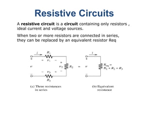
A resistive circuit is a circuit containing only resistors ,
ideal current and voltage sources.
When two or more resistors are connected in series,
they can be replaced by an equivalent resistor Req
2. General Methods For Series Circuits
• When I for one component is known, use this I for all
component , as the current is same for all parts of a series
circuit
• To calculate I, the total voltage can be divided by the total
resistance or an individual IR can be divided by its R. However
do not mix a total value for the entire circuit for an individual
value for only part of the circuit.
• When the individual voltage drops around the circuit are
known these can be added equals to applied voltage.
3. Parallel Circuits
When two or more resistors are connected in parallel, they
can be replaced by an equivalent resistor Req
4. General Methods For Parallel Circuits
• When voltage across one branch is known this
voltage is across all the branches. There can
be only one voltage across branch points with
the same potential difference
• If total current 𝑖 is known and one of the
branch current 𝑖1, 𝑖2 can be find by
subtracting 𝑖1 from 𝑖 total
5.
6.
7. 1. Begin by locating a combination of
resistances that are in series or parallel.
Often the place to start is farthest from
the source.
2. Redraw the circuit with the equivalent
resistance for the combination found in
step 1.
Circuit Analysis using Series/Parallel
Equivalents
8. 3. Repeat steps 1 and 2 until the circuit is
reduced as far as possible. Often (but not
always) we end up with a single source and
a single resistance.
4. Solve for the currents and voltages in the
final equivalent circuit.
9. Example: Find the current, voltage and power for each element
in the circuit shown in below fig
10. Example: Find the currents labeled in fig , by cobining
resistances in series and parallel.
11.
12. Voltage Division
Any Series Circuit is a voltage divider. The IR
voltage drop are proportional parts of the
applied voltage
14. Of the total voltage , the fraction that appears
across a given resistance in a series circuit is
the ratio of the given resistance to the total
resistance.
Voltage Division Principle
15. Application of the Voltage-
Division Principle
Find the voltage v1 and v4.
16. Current Division
Any Parallel Circuit is a current divider. Each
branch is part of the total line current, but
inverse proportion to the branch resistance.
18. For two resistances in parallel, the fraction of
the total current flowing in a resistance is the
ratio of the other resistance to the sum of the
two resistances.
Current Division Principle
19. Exercise :Use the voltage-division principle to find the voltage Vx in fig. Then find the source current is
and use the current division principle to compute the current i3..
20. Application of the Current-
Division Principle
Exercise : Use the current division principle to find the current i1 in the fig.
21. Application of the Current-
Division Principle
20
60
30
60
30
3
2
3
2
eq
R
R
R
R
R
A
10
15
20
10
20
eq
1
eq
1
s
i
R
R
R
i
22. Exercise: Use the Voltage-division principle to find the voltages in the fig.
23. Exercise: Use the current-division principle to find the current labeled in fig