JVC DT-3D-24-G1
•
0 likes•112 views

The document introduces JVC's new 3D monitor, the DT-3D24G1. It is a compact 24" monitor that supports the creation of high quality 3D content both in editing studios and on location. The monitor features various functions for checking 3D camera settings and ensuring proper alignment of left and right images, including image rotation, splitting, sequential display, and a 3D cursor for adjusting depth. It also displays dual timecode and inputs signals from 3D cameras through SDI and DVI connectors. The compact design makes it suitable for location work as well as studio editing.

Recommended
More Related Content
What's hot
What's hot (14)
Similar to JVC DT-3D-24-G1
Similar to JVC DT-3D-24-G1 (20)
More from AV ProfShop
More from AV ProfShop (20)
Recently uploaded
Recently uploaded (20)
JVC DT-3D-24-G1
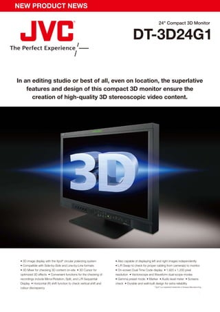
- 1. NEW PRODUCT NEWS 24" Compact 3D Monitor DT-3D24G1 In an editing studio or best of all, even on location, the superlative features and design of this compact 3D monitor ensure the creation of high-quality 3D stereoscopic video content. • 3D image display with the Xpol® circular polarizing system • Also capable of displaying left and right images independently • Compatible with Side-by-Side and Line-by-Line formats • L/R Swap to check for proper cabling from camera(s) to monitor • 3D Mixer for checking 3D content on-site • 3D Cursor for • On-screen Dual Time Code display • 1,920 x 1,200 pixel optimized 3D effects • Convenient functions for the checking of resolution • Vectorscope and Waveform dual-scope modes recordings include Mirror/Rotation, Split, and L/R Sequential • Gamma preset mode • Marker • Audio level meter • Screens Display • Horizontal (R) shift function to check vertical shift and check • Durable and well-built design for extra reliability * Xpol® is a registered trademark of Arisawa Manufacturing. colour discrepancy
- 2. NEW PRODUCT NEWS ❚ 3D monitor on a location ❚ Supports virtually any 3D camera setting Achieving the desired 3D effects without an appropriate monitor for 3D video 3D camera settings can be configured in many ways so to facilitate checking of production can be a very cumbersome and time-consuming process, especially whether the left and right images are correctly aligned, a number of monitor on location. However, JVC’s new DT-3D24G1 not only delivers superb functions are required to ensure the best 3D camera setting for the situation. performance in editing studios but is also even compact enough to take along The DT-3D24G1 features all the necessary image rotation features to support on location. And thanks to its Mixer function, this monitor enables the checking even the most complicated 3D camera settings. of 3D effects immediately on-site without any additional equipment. The • Mirror/Rotation: One of the two images is reverted laterally and/or vertically adoption of an easy-to-manage Xpol® circular polarizing system also makes to a normal viewing position and automatic delay is added to non-rotated screen checking simpler and smoother. images one at a time to synchronize both images. Half mirror rig ❚ 3D Cursor function Beam-splitter rig SDI-R To create 3D video, scenes are recorded by adjusting the binocular disparity Mirror against an object to make it appear to either pop up or immerse deeper into the scene. And until now, creators had to visually count the number of dots in the Image on the right is reverted. screen to adjust binocular disparity, which can be a rather complicated and 3D camcorder rig tedious process. However, the DT-3D24G1 helps to greatly simplify production thanks to its 3D Cursor function. This convenient function displays left, right, SDI-R and horizontal lines over target scenes on the screen, enabling binocular Rotation disparity to be easily fine-tuned just by adjusting the camera settings and this helps to ensure optimized 3D effects. Image on the right is inverted. Green lines are used to adjust depth whereas the pink lines regulate pop-up levels. The horizontal line • Split: Useful for fine-tuning requirements such as setting recording positions is moved to a position where binocular disparity is to in the vertical direction, L/R iris differences, and white balance adjustment. be checked first, and then the L or R line is moved to a position where binocular disparity is Images on the left of the vertical line in the screen are from the left camera and subsequently checked. The values of binocular accordingly, right images are from the right camera. disparity will be displayed on the screen by either the number of pixels or percentage. 60 pixels 9.00% 20 pixels -3.00% Horizontal line is used as a guide Horizontal line is used as a uide Example of mismatched Example of vertical shift Example of mismatched iris adjustment in the recording position white balance When the lines become red, it is a warning sign • Horizontal (R) Shift: In order to check vertical shift or colour discrepancy, indicating that the amount of binocular disparity the right camera image can be shifted to the left to overlap with the left has surpassed the acceptable stereoscopic viewing level. camera image, which is static. ❚ Dual Time Code The DT-3D24G1 displays on screen, the time code of both left and right signals as well as the time gap between the two signals. When the monitor is in 3D Display mode, the time code of the left signal will be displayed on the top right • L/R Swap: Allows left and right images to be of the screen. swapped, and helps in checking whether the cables are properly connected. R TC:--:--:--:-- TC1 TC1:00:00:00:15 R L TC2:00:00:00:12 DIFF:±00:00:00:03 L • Sequential L/R Switching: Left and right images are displayed alternately at 0.5-sec intervals, making this method ideal for content creators as 3D glasses are not necessary for viewing. • Dual Scope: Waveform and Vectorscope monitoring allow the user to easily ❚ Inputs and Connectors check and monitor input signals from the two channels to facilitate adjustment The DT-3D24G1 features an array of external input terminals such as SDI x 2 of the cameras. (active through), 3G-SDI, SDI dual link, DVI x 1 (HDCP) and Audio x 1. The position of the scopes can also be located on any of the monitor’s four corners. E. & O.E. Design and specifications subject to change without notice. All TV screen pictures are simulated. All brand or product names may be trademarks and/or registered Waveform (W.F.M.) Vectorscope (V.S.) trademarks of their respective owners. Any rights not expressly granted herein are reserved. Copyright 2010, Victor Company of Japan, Limited (JVC). All Rights Reserved. DISTRIBUTED BY Printed in Japan ICN-0400 “JVC” is the trademark or registered trademark of Victor Company of Japan, Limited.