8. Item Cost
Battery Pack $171
Solar Panels $40
Immersion Coil $10
Electrical Wire $2
System Integration Parts $30
Total $253
The prices listed above are based on testing costs. There are several opportunities for cost
savings that we hope will reduce the prototype cost of the system to approximately $200. These
opportunities include having to make some parts rather than purchase them, and having a better
understanding of the gages and lengths of wire required to build the system.
8
14. ➢ Crank:
o Pros:
▪ Easy to use
▪ Cheap
▪ Use it in any weather condition
o Cons:
▪ Littletonone energy output
▪ Required too much energy from the person
▪ Bulky
Aaron, Arthur and Sandra organized all the ideas above into a decision matrix, presented it to the
group, and then the group made some final decisions. We ended up choosing thermoelectric
generator and solar panels. Solar panel because it was the most reliable source of main energy,
according to our decision matrix (shown below). However, we still needed a second power
source in case the weather became unfavorable, so we also chose the thermoelectric generator.
Figure: Decision Matrix
Approach
Our group met every Wednesday from 2:303:30 p.m. in the Aggie Innovation Space conference
room. We discussed ideas, progress and next steps. Whoever came up with an idea, had to do
individual research to provide the pros and cons, and then would be examined by the rest of the
group. Every member had his/her own strengths, and tasks were assigned accordingly.
The group administrators (Reese, Arthur and Sandra) met with our advisor, Dr. Abdelkefi, most
Mondays from 1:302:00 p.m. in his office. The administrators kept Dr. Abdelkefi uptodate on
what was discussed during our Wednesday meeting. Dr. Abdelkefi would provide feedback to
our current struggles, strategies and successes.
14
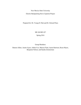
19. Energy Input Assessment:
Solar
Power
Hand
Crank
Piezo
Electric
Water/Wind
Turbine
Cost 7 6 4 4
Power
Input
6 8 2 9
Weight/Siz
e
6 6 8 8
Complexity 7 10 3 3
Ease of Use 10 3 8 10
Safety 9 9 8 8
Total 45 42 33 42
For our renewable energy choices, we looked into solar panels, thermoelectric generators,
piezoelectric transducers, a wind/hydro turbine, and a hand crank. After doing research in each
of these fields, it became apparent that either solar panels or a turbine would be our best option
for a main rechargeable power source; however, weather conditions could interfere with their
performance, so we decided to include an additional power source to supplement them. We
looked into incorporating either the thermoelectric generator, the piezoelectric transducer, or the
hand crank to be the supplemental power source.
Solar panels became our main option for power over turbines for a couple of reasons. The
turbine would generate more power than the solar panel but the main problem was the size and
complexity of the design that made it unfeasible. The blade diameter had to be at least a foot in
size making it impractical to carry and in turn made the turbine too heavy. Solar panels can be
set in series giving us the desired output of energy. Also, buying solar cells gives us the
flexibility to model and attach the solar panels for travel in a way that is comfortable and
lightweight. The solar panels would weigh in roughly around one pound and are relatively easy
to wire. The main concern for the solar panels is not having sunlight, thus creating the use for
supplemental power sources.
For our supplemental power sources, all three did not have a high power output making them a
bad choice for a main power source. The piezoelectric transducer was ruled out due to the fact
that it was too complex for both the user and for us to manufacture. It ran off of AC current and
our battery was running off of DC current, meaning we needed to convert the current. Also, the
19
26. Bill of Materials and Supplier Identification
➢ Solar Panel Test:
Supply Quantity Supplier Total Cost
80’ Solar Cell Tabbing
Wire
1 Amazon.com $14.09
8’ Solar Cell Bus Wire 1 Amazon.com Included in
price
above
Solar Flux Pen 1 Amazon.com Included in
price
above
Solar Panel Diode 2 Amazon.com Included in
price
above
Monocrystalline cell solar
panels
125mmx125mm at
2.8W
10 Amazon.com $25.99
4’x8’x1/4” OSB wood
sheet
2 Home Depot $3.84
2’x4’x10’ plank of wood 1 Home Depot $3.84
30A fuse 1 Home Depot $4.36
Gorilla glue adhesive 1 Home Depot $18.36
Pack of 40 wood screws 1 Home Depot $15.37
Timer 1 Target borrowed
26
27.
➢ Battery Test:
Supply Quantity Supplier Total Cost
3.2V 20Ah LiFePO4 batteries 4 Allbattery.com $143.96
Protection Circuit Module 1 Allbattery.com $35.95
3.2V charger 1 Batteryspace.com $80.64
5 yards of nickel chromium
wire
1 Amazon.com $7.86
Backpacking pot minimum
with a volume of 1L
1 Target $4.99
Insulated Styrofoam
container
1 Target $9.98
Spoon 1 Target $0.98
10 yards of 10gauge copper
wire
1 Home Depot $11.48
10A fuse 2 Home Depot $4.56
Multimeters 2 New Mexico State
University
borrowed
Thermocouple 1 New Mexico State
University
borrowed
Timer 1 Target borrowed
27
33. ○ 2 leads of copper wire (gauge to be determined)
➢ Test Procedure
1. Instrument boiling pot with Thermocouples (orientation to be determined when we know
how many thermocouples we will have)
2. Fill pot with 1L of water
3. Immerse resistance coil in water, avoid contact with sides or bottom of container
4. Place 1 thermocouple at center of resistance coil
5. Place 1 thermocouple between resistance coil and wall of container
6. Start recording Thermocouple data
7. Start timer and connect leads to battery
8. Monitor battery temperature, disconnect leads if battery temperature reaches 60C
9. When water reaches rolling boil, stop time and disconnect battery lead.
10. Save Thermocouple data to a flash drive as “Test_1_Boil_Data.xls”
11. Wait until resistance coil has cooled to below 30C
12. Fill an insulated container with 4 L of water
13. Immerse resistance coil in water, avoid contact with sides or bottom of container
14. Place 1 thermocouple at center of resistance coil
15. Place 1 thermocouple between resistance coil and wall of container
16. Start recording Thermocouple data
17. Start timer and connect leads of battery
18. Monitor voltage at battery leads, when voltage drops below 10.8V disconnect leads and
stop timer
19. Save Thermocouple data to flash drive as “Test_1_SpecificHeat_Data_xls”
33
34. ➢ Analysis:
1. For boil data, calculate:
a. Time to boil
b. Efficiency
2. For specific heat, calculate:
a. Actual Capacity/Advertised Capacity
Test Setup
Materials Used:
➢ MSR Stainless Steel Pot
○ 7 inch Diameter
○ 3 inch Deep
○ 115.5 in^3 Volume
➢ Battery Pack
○ 4 3.38V LIFePO4 Battery Cells
○ 1 Circuit Discharge Controller
○ 10 Gage Copper Wire
○ Custom Foam Board Battery Case
➢ NiChrome Wire
○ 1ft Coil
■ Measured Resistance: 4.5 Ohms
■ Calculated Resistance: 2.25 Ohms
○ 2ft Hex Coil
■ Measured Resistance: 9 Ohms
■ Calculated Resistance: 4.5 Ohms
➢ 1 Liter Tap Water
Upon arrival at the designated lab space, a class was underway where the test was to take place.
Arthur spoke with Dr. Ben Ayed and the test was moved to the lab next door. This required the
computer with the thermocouple software to be moved to the new testing room. Despite
repeated attempts, the supervising TA, Arthur and Reese were unable to log on to the computer.
As an alternative, we used the the multimeter with a single thermocouple.
A NiChrome coil was prepared prior to testing based on the resistivity and dimensional qualities
of the wire. When the resistance was measured using two separate multimeters, the resistance
34
36. 4. The switch was turned back to the “ON” position, temperature and voltage readings were
recorded every 30 seconds.
5. Again localized vaporization was immediately evident and temperature began to rise a
measurable amount.
6. Water became yellowish in color, with some foam after several minutes, exact time not
noted.
7. Initial thermocouple began reading temperatures above 218F and was replaced, readings
away from coil with new thermocouple showed 180F
8. After 40 minutes water was still not boiling, fairly uniform temperature of 188 was
recorded. Test was stopped.
9. Upon closer inspection, alligator clip no longer has chrome like finish but appears to be
made up of copper. Uncertain as to whether copper has plated the clip or the finish has
corroded leaving copper exposed.
10. Resistor is coated with some kind of yellowish dull substance, unsure what origin of
substance is.
11. Battery pack remains cool to the touch throughout both iterations
12. Insulated container testing was not conducted due to failure of first test.
36
42. ➢ Materials/Apparatus:
1. Solar Panel Electrical Setup Kit
2. Solar Panel 10x
3. 4’x8’x1/4” OSB Sheet
4. Screws
5. 7A Fuse
6. 2x4x10
7. Spray adhesive
These materials were assembled in such a way to mimic certain orientations that the backpacker
might use during operation.
Figure 6: Solar Panel Testing Apparatus
➢ Test Procedure:
1. Cut three OSB panels 15”x6”
2. Frame panels with 2x4
42
43. 3. Orient boards 115 degrees end to end to construct a trapezoid
4. Spray adhere 3 solar panels to each of the osb panels
5. Solder panels together in series
6. Solder connection wires to be used in power measurements to complete each circuit for
the entirety of the array as well as each individual panel
7. Orient solar panel array from east to west.
8. Testing the entire array:
a. Connect two multimeters to the test leads
b. Testing time is from 9 a.m. to 3 p.m.
c. Take measurements of both amperage and voltage every thirty minutes
9. Testing individual panels:
10. Repeat steps 8 ac
Testing will follow this plan strictly. We hope to obtain data relating to the amount of power
output from the system. Obviously, the energy output is proportional to the sun’s position. This
means that the individual cells that are closer to perpendicular to the sun’s angle will have a
greater power output. (Measurement will be performed using a multimeter.)
➢ Results
After assembling and testing the solar cell array, we feel that the testing provided satisfactory
results. There was an incident of a broken solar panel that happened towards the end of testing.
While attempting to remove the alligator clip from the buss wire while detaching the
multimeter, one of the cells was shattered. Because this happened at the end of testing, we
believe the data to still be relevant and valuable. The continuity of the system was not
compromised, so the broken cell was positioned to be one of the three sides in the shade. This
breakage of the panel did not appear to affect the results seeing how consistent the results
remained even with the broken cell still attached. The reason the 10th
cell was not used to repair
this while testing is during the initial assembly an additional cell was destroyed due to their
fragility. We expect that more cells will be needed to be a usable method of recharge for our
system. The obtained results are as follows:
43
47. Weekly Progress Report #1
To: Dr. Park
From: Electric Backpacking Stove
Subject: Weekly progress report #1
Date: February 10, 2016
WHEN DID THE TEAM MEET AND WHO ATTENDED
▪ 02/03/16 and 02/10/16
▪ Meeting Attendees: Reese Myers, Arthur Cox, Sandra Zimmerman, Austin Ayers,
Damon Alfaro, Marcus Fluitt, Aaron Harrison, Benjamin Nelson
WHAT OUR TEAM ACCOMPLISHED THIS WEEK
▪ As group:
▪ Established roles: Reese lead engineer, Arthur team leader, Sandra
documentation leader
▪ Established system requirements
▪ Delegated research for system components, agreed to discuss methods of
fulfilling system requirements.
▪ Problems encountered: how to recharge our battery portably
▪ Compared individual research results
▪ Individually
▪ Solar panel research: Aaron and Marcus
● Will be a problem if the backpacker does not have access to sunlight.
▪ Crank research: Austin
● Does not provide a sufficient amount of energy for power our stove
▪ Energy harvesting research: Sandra
● It is a decent source for power but needs to be paired with another
method to get enough power for our stove
▪ Calculations: Reese
47
48. ▪ Types of batteries research: Arthur, Damon, Ben
WHAT WE ARE DOING NOW
▪ As group & individually
▪ Planning this week’s individual duties.
● Research methods for heat transfer: Reese and Marcus
● Battery research: Damon and Ben
● Solar research: Aaron and Austin
● More energy harvesting methods: Sandra and Arthur
WHAT WE NEED TO DO NEXT
▪ Schedule meetings for every Wednesday at 2:30 pm
▪ Find an advisor: maybe Dr. Abdelkefi??
▪ Research methods of heat transfer, batteries, solar energy and energy harvesting
▪ Budget
▪ Do more calculations
48
49. Weekly Progress Report #2
To: Dr. Park
From: Electric Backpacking Stove
Subject: Weekly progress report #2
Date: February 17, 2016
WHEN DID THE TEAM MEET AND WHO ATTENDED
▪ 2/17/16
▪ Meeting attendees: Reese Myers, Marcus Fluitt, Austin Ayers, Benjamin Nelson,
Aaron Harrison, Sandra Zimmerman, Damon Alfaro, and Arthur Cox
WHAT OUR TEAM ACCOMPLISHED THIS WEEK
▪ As group:
▪ met with our new advisor, Dr. Abdelkefi
● attendees: Reese Myers, Sandra Zimmerman, Arthur Cox, and Benjamin
Nelson
▪ discussed the possibility of using a hybrid energy harvester such as combining
piezoelectric, thermoelectric and solar
▪ meeting minutes (attached below)
▪ discussed individual work
▪ Individually:
▪ Aaron and Austin:
● Solar panel options:
o 2.5 W per cell (40 cells weigh 15.2 oz)
o 2.8 W per cell (10 cells weigh 2.2 lb)
o Considering about 5 hours of direct sunlight a day, we can
produce 26.8 W
● Calculated possible coil/solar options
▪ Damon and Ben:
49
50. ● Batteries:
o 15 oz LiIon Battery 10Ah can charge 40A
o Poly LiIon 10Ah, energy density: 170 wh/kg, weighs: 2.15
kg
o Lithium Iron Phosphate 16V 20Ah has 100% voltage until
it dies
▪ Marcus and Reese:
● Heat transfer method:
o Ruling out induction
o Possible options:
▪ immersion coil conducts straight to water, any pot
material will work, remove a layer of resistance,
compact size
▪ wrapping coil no lid problems, would enable a lot
of surface area for heat conduction
▪ electric burner no lid problems, would enable
cooking eggs again
▪ Sandra and Arthur:
● Energy harvesting:
o Thermoelectric (converting heat energy into electricity)
▪ Requires low temp side and a high temp side
▪ Can cool the low temp side with water or air (we
would use air)
▪ Products already using thermoelectric generators:
woods stoves
▪ Benefit: can recycle the energy lost as heat
o Electromagnetic transducer:
▪ Can produce 300*10^6 W to 2.5mW per step
(varies depending on weight)
▪ Where to place it (i.e. backpack, sleeve)
50
52. Weekly Progress Report #3
To: Dr. Park
From: Electric Backpacking Stove
Subject: Weekly progress report #3
Date: February 24, 2016
WHEN DID THE TEAM MEET AND WHO ATTENDED
▪ 2/24/16
▪ Meeting attendees: Reese Myers, Marcus Fluitt, Austin Ayers, Benjamin Nelson,
Aaron Harrison, Sandra Zimmerman, Damon Alfaro, and Arthur Cox
WHAT OUR TEAM ACCOMPLISHED THIS WEEK
▪ As group
▪ Discussed Dr. Abdelkefi’s suggestions:
● Start with boiling water off of a battery
● Figure out resistance coil
● How many ounces of water the battery can boil
● All of the above will give us a better idea of efficiencies
● Deploy more people towards figuring out coil
▪ Discussed individual work
▪ Individually
▪ Aaron/Austin:
● Solar panel:
o Need 33.6 W per day for solar
o 5 hours of sunlight gives us 484000 J (energy stored)
o Went over possible solar panel options
● DC Immersion coil: 12 V 60 W
52
53. o 11 min till boil
▪ Damon/Ben:
● Batteries:
o 420 WH for three days
o To recharge battery with one day’s sunlight using solar:
33.6W
o Lightest option:
▪ Weight for 7 batteries: 3.57 lb
▪ cost: $244.65
▪ Marcus/Reese:
● Maximizing Power Transform Theorem:
o to get maximum power from a given volt source the
resistance of what you are powering should match the
resistance of the volt source
o Internal resistance heats up the battery
o Can play with our range of resistance
● Immersion coils:
o Doable
▪ Sandra/Arthur:
● Energy harvesting:
o Thermoelectric:
▪ Possible options:
● Thermoelectric Power Generation Generator
50x50 mm Tile Max Load
o Weight: 1.6 oz
o Price: $29.99
● 40 * 40mm Thermoelectric Power Generator
High Temperature
o Weight:
o Price: $7.99
o Piezoelectric:
▪ Possible options:
● Piezo Ceramic Generator 40x11x1.7 mm
53
54. o $19.00 for 2
● Possibly use a pressure cooker??? More to come.
WHAT WE ARE DOING NOW
▪ As group & individually: We are working on narrowing down our possibilities for the
battery and the hybrid energy harvester. So far, we’ve laid out the pros and cons to each
energy harvester:
▪ The piezo is cheap and doesn’t add any weight to our device.
▪ The electromagnetic would add weight, but it isn’t too expensive.
▪ The thermoelectric generator is great because we can recycle the heat that the
stove produces to power the stove.
▪ The solar panels produce the most energy, but can be pricey.
WHAT WE NEED TO DO NEXT
▪ Prepare one PowerPoint slide for each subgroup’s conclusions because our
advisor wants us to be organized.
▪ Work on our subgroup research:
▪ Aaron and Austin: Double check energy requirements
▪ Damon and Ben: Look at resistance stuff internal resistance, wattage
output
▪ Sandra and Arthur: figure out power output for thermoelectric, figure out
whether piezo or electromagnetic is better
▪ Reese and Marcus: Also look at resistance stuff internal resistance,
wattage output
54
55. Weekly Progress Report #4
To: Dr. Park
From: Electric Backpacking Stove
Subject: Weekly progress report #4
Date: March 2, 2016
WHEN DID THE TEAM MEET AND WHO ATTENDED
▪ 3/2/16
▪ Meeting attendees: Reese Myers, Marcus Fluitt, Austin Ayers, Benjamin Nelson,
Aaron Harrison, Sandra Zimmerman, Damon Alfaro, and Arthur Cox
WHAT OUR TEAM ACCOMPLISHED THIS WEEK
▪ As group
▪ Discussed Dr. Abdelkefi meeting:
● Doing a hybrid system will complicate the circuitry
● Where will we place each system?
▪ Discussed individual work
▪ Individually
▪ Aaron/Austin:
● Solar panel:
o Checked calculations
o Max power of sun we can get without requiring the
customer to worry about aiming his backpack toward the
direction of sunlight.
▪ Damon/Ben:
● Batteries:
o Narrowed down batteries
o Calculated power requirements
▪ Marcus/Reese:
55
56. ● Resistance:
o Maximize current
o Resistance is dictated by battery pack voltage
o Coil length and form can be optimized
o High amperage produces more heat
▪ Sandra/Arthur:
● Energy harvesting:
o Find piezo less than 100 Hz
o 8 hours where the customer isn’t generating energy from
sunlight or walking
▪ Use a turbine during that downtime
● power it using the creek’s water motion
WHAT WE ARE DOING NOW
▪ As group & individually: We are working on how to be more efficient with our
research. We have set goals to be met by the start of spring break:
▪ Create a decision matrix:
● Do we have knowledge or resources, cost, feasibility, human factor
and weight?
▪ Talk with Dr. Tom Jenkins for solar panel stuff
WHAT WE NEED TO DO NEXT
▪ Maximize current, make a test plan, write a proposal, order parts
▪ Form new groups:
▪ Recharge research:
● Sandra, Arthur, and Aaron
o Combine solar with energy harvesting, isolate 2 or 3
systems to use for our hybrid
o Calculate how much energy we are going to generate for
the average person
▪ Testing schematic/Test scaling:
● Ben, Marcus and Damon
o Work on circuitry diagrams, draw a sketch for the boiling
water component of our project, handle budget and
feasibility, and consider what the customer wants
▪ Test plan:
● Austin and Reese
o Work on apparatus, procedures, etc.
56
57. Weekly Progress Report #5
To: Dr. Park
From: Electric Backpacking Stove
Subject: Weekly progress report #5
Date: March 9, 2016
WHEN DID THE TEAM MEET AND WHO ATTENDED
▪ 3/9/16
▪ Meeting attendees: Reese Myers, Marcus Fluitt, Austin Ayers, Benjamin Nelson,
Aaron Harrison, Sandra Zimmerman, Damon Alfaro, and Arthur Cox
WHAT OUR TEAM ACCOMPLISHED THIS WEEK
▪ As group
▪ Discussed Dr. Abdelkefi meeting:
● Need to talk with Dr. Ayed for lab testing.
● We need to test thermocouples to determine if the thermoelectric
generator will work
▪ Discussed subgroup work
▪ Individually
▪ Austin/Reese: Test Plan
● Wrote out the objective (shown in meeting minutes)
● Wrote out the test procedure (shown in meeting minutes)
● Set up the analysis (still in progress)
▪ Ben/Marcus/Damon: Testing Schematic/Test Scaling
● Determined requirements for current using different gages of wire
● Looked up different sets of batteries based of the calculations
● More current, more output
▪ Arthur/Sandra/Aaron: Recharge Research
57
58. ● Decision Matrix: Solar panel ended up with the highest total
● Hydro/Wind Turbine: Still looking at it as a possibility
o Rio Grande stream velocity: 12 ft/min
WHAT WE ARE DOING NOW
▪ As group & individually: We have set goals to be met by the Wednesday after spring
break:
▪ Finish most of the theoretical research
▪ Start testing the battery, the time it takes the water to boil, and the
thermoelectric generator
WHAT WE NEED TO DO NEXT
▪ Maximize current, make a test plan, write a proposal, order parts
▪ Subgroups:
▪ Recharge research: (Sandra, Arthur, Ben and Aaron)
● Hydro/Wind Turbine: Find torque required and energy that can be
captured from the wind and the water
● Solar energy:
o Flux
o Setup for panels
▪ Testing schematic/Test scaling: (Marcus and Damon)
● Compose drawings of the battery and the circuits
● Determine connection between the battery and the wire
▪ Test plan: (Austin and Reese)
● Create proposal and send out today
● Finish test plan
58
59. Weekly Progress Report #6
To: Dr. Park
From: Electric Backpacking Stove
Subject: Weekly progress report #6
Date: March 30, 2016
WHEN DID THE TEAM MEET AND WHO ATTENDED
▪ 3/23/16
▪ Meeting attendees: Reese Myers, Marcus Fluitt, Austin Ayers, Benjamin Nelson,
Aaron Harrison, Sandra Zimmerman, Damon Alfaro, and Arthur Cox
WHAT OUR TEAM ACCOMPLISHED THIS WEEK
▪ As group
▪ Discussed subgroup work
▪ Discussed the opportunity to use Dr. Ayed’s lab to test the battery, the solar
panel and the thermoelectric generator.
● Details:
o Can only use it when one of her lab assistants is present.
o Need to write up a proposal on what we are doing and how we
are going to do it, and submit it to Dr. Garcia for approval.
▪ Individually
▪ Marcus/Damon/Reese/Austin: Testing components
● Submitted test plan for battery
▪ Arthur/Sandra/Aaron/Ben: Recharge research
● Decided that the wind/turbine is too expensive, large and heavy.
● Decided that the piezoelectric generator is too complex because we
would need to figure out how to change its AC voltage to DC.
59
61. Weekly Progress Report #7
To: Dr. Park
From: Electric Backpacking Stove
Subject: Weekly progress report #7
Date: April 6, 2016
WHEN DID THE TEAM MEET AND WHO ATTENDED
▪ 3/30/16
▪ Meeting attendees: Reese Myers, Marcus Fluitt, Austin Ayers, Benjamin Nelson,
Aaron Harrison, Sandra Zimmerman, Damon Alfaro, and Arthur Cox
WHAT OUR TEAM ACCOMPLISHED THIS WEEK
▪ As group
▪ Discussed PDR session
● Dr. Pines feedback:
o Start working on binder
o Increase our budget to $500—don’t worry too much about
money
▪ Discussed solar panel test plan
▪ Individually
▪ Austin, Damon, Marcus, Arthur and Aaron
● Solar panel testing:
o Place the solar panel cells in trapezoid to insure we get the
angle of sun at all times of the day
61
62. WHAT WE ARE DOING NOW
▪ As group & individually:
▪ We are submitting our solar panel test plan
▪ We are planning to move forward with the battery testing, but first Arthur
has to order parts.
WHAT WE NEED TO DO NEXT
▪ Work on facets 13
▪ Group 1: (Reese and Marcus)
● Write up facet 1
▪ Group 2: (Austin and Damon)
● Write up facet 2
▪ Group 3: (Sandra and Aaron)
● Write up facet 3
▪ Test plan/Testing schematic/Test scaling: (Arthur and Ben)
● Discuss battery prices
● Figure out what to order
62
63. Weekly Progress Report #8
To: Dr. Park
From: Electric Backpacking Stove
Subject: Weekly progress report #8
Date: April 13, 2016
WHEN DID THE TEAM MEET AND WHO ATTENDED
▪ 4/6/16
▪ Meeting attendees: Reese Myers, Austin Ayers, Benjamin Nelson, Aaron Harrison,
Sandra Zimmerman and Arthur Cox
WHAT OUR TEAM ACCOMPLISHED THIS WEEK
▪ As group
▪ Discussed:
● Gantt Chart: (composed by Reese)
o To organize our next steps
o Steps include:
▪ Reserve testing location for battery and solar panel
▪ Build battery pack and solar test setup
▪ Perform battery test and solar panel test
▪ Individually
▪ Group 1: (Reese and Marcus)
● Finished facet 1
▪ Group 2: (Austin and Damon)
● Almost finished facet 2
▪ Group 3: (Sandra and Aaron)
63
64. ● Finished facet 3
WHAT WE ARE DOING NOW
▪ As group & individually:
▪ Arthur is ordering parts and scheduling a time to use the lab for battery
testing
▪ Waiting to test our battery
WHAT WE NEED TO DO NEXT
o Schedule the groups for testing:
▪ Subgroup work:
● Battery testing: Ben, Reese, and Damon
o Build the battery pack and perform the lab testing in a few
weeks
● Solar Panel testing: Austin, Aaron, and Marcus
o Setup the frame and perform the solar panel test in a few
weeks
● Facet editing/composing: Sandra and Arthur
● Scheduling/ordering and purchasing parts: Arthur
64
65. Weekly Progress Report #9
To: Dr. Park
From: Electric Backpacking Stove
Subject: Weekly progress report #9
Date: April 20, 2016
WHEN DID THE TEAM MEET AND WHO ATTENDED
▪ 4/13/16
▪ Meeting attendees: Reese Myers, Damon Alfaro, Austin Ayers, Benjamin Nelson and
Sandra Zimmerman
WHAT OUR TEAM ACCOMPLISHED THIS WEEK
▪ As group
▪ How to go about building the battery
▪ Subgroup research
▪ Individually
▪ Battery testing: Ben, Reese, and Damon
● Waiting on ordered parts to come in
▪ Solar Panel testing: Austin, Aaron, and Marcus
● Waiting on ordered parts to come in
▪ Facet editing/composing: Sandra and Arthur
● Edited facet 3
WHAT WE ARE DOING NOW
▪ As group & individually:
▪ Reese is checking up on battery arrival
65
66. ▪ Reese is following up with Arthur on reserving battery testing space two
days after arrival
WHAT WE NEED TO DO NEXT
o Subgroup work:
▪ Battery testing: Ben, Reese, and Damon
● Still waiting on ordered components/lab space availability
● Need to solder outside of the lab
▪ Solar Panel testing: Austin
● Build frame for solar panel testing today
● Test is outside—do not need to reserve lab space
▪ Facet editing: Sandra and Arthur
● Need to edit Facets 1 and 2
▪ Taking care of ordered system components: Arthur
● Still in progress
▪ Composing facet 4: Aaron and Marcus
▪ Writing the intro and method section for final report: Sandra and Reese
66
67. Weekly Progress Report #10
To: Dr. Park
From: Electric Backpacking Stove
Subject: Weekly progress report #10
Date: April 27, 2016
WHEN DID THE TEAM MEET AND WHO ATTENDED
▪ 4/20/16
▪ Meeting attendees: Reese Myers, Damon Alfaro, Aaron Harrison, Marcus Fluitt,
Arthur Cox, Austin Ayers, Benjamin Nelson and Sandra Zimmerman
WHAT OUR TEAM ACCOMPLISHED THIS WEEK
▪ As group
▪ Subgroup research
▪ Individually
▪ Arthur: scheduled lab testing for battery for Wednesday, April 27 in room 137
from 2:30 to 4:00 p.m.
▪ Aaron and Marcus
● Wrote facet 4
▪ Sandra:
● Wrote rough draft for methods section of final report
▪ Reese:
● Wrote rough draft for intro section of final report
WHAT WE ARE DOING NOW
▪ As group & individually:
▪ Fixing the battery for testing
▪ Composing the binder
67
69. Weekly Progress Report #11
To: Dr. Park
From: Electric Backpacking Stove
Subject: Weekly progress report #11
Date: May 4, 2016
WHEN DID THE TEAM MEET AND WHO ATTENDED
● 4/27/16 and 5/4/16
● Meeting attendees: Reese Myers, Damon Alfaro, Aaron Harrison, Marcus Fluitt, Arthur Cox,
Austin Ayers, Benjamin Nelson and Sandra Zimmerman
WHAT OUR TEAM ACCOMPLISHED THIS WEEK
● Individually
○ Binder work:
■ Arthur and Sandra: facet 5
■ Marcus and Aaron: started facet 6
■ Austin: Solar panel testing report
■ Damon and Ben: Battery testing report
■ Reese: started final report
■ Sandra: put binder together
WHAT WE ARE DOING NOW
● As group & individually:
○ Finalizing binder
69