SlideShare a Scribd company logo
1 of 148
Download to read offline
Construction of a Steam Powered
Model Car for Educational Purposes
of Thermodynamics and Power
Calculations
Andrew Paul McLellan (S1222569)
Main Body Word Count 16,540
The design, assembly and testing through the use of CAD software,
calculation and manufacturing techniques a teaching aid in the form of
a model engine driven by steam for 1st and 2nd Year Engineering
students to perform thermodynamics and power calculations on a
physical model.
i
Abstract
The aim of this project was to create a teaching aid that would be a useful tool for lecturers
of Thermodynamics and Engineering Design and Analysis. The thought behind this being that
testing of a physical model could help consolidate theory learned in lectures and tutorials
providing students with a better understanding of the applications of what they have
learned in the classroom. This was achieved through the design, manufacture and testing of
a model engine powered by a pressurised vessel containing steam. With applications for
thermodynamics calculations, and engine torque and power calculations, a small steam
engine provided a wide-range of applications for the lecturer to relate to the curriculum.
The engine was taken from the initial design stage with different engine concepts considered
before deciding on the most suitable design due to a variety of factors. These components
were created using computer aided design software and where then manufactured using a
variety of manufacturing methods in the university engineering applications workshop.
These included 3-axis machining and 3D rapid prototyping techniques. With the completion
of component manufacturing, the assembly and testing of the engine was then undertaken.
All tests conducted had a high emphasis on safety due to the nature of the model’s intended
environment of application. Numerous steps were taken throughout the various sections of
the testing phase to ensure personal safety and to make the system as safe as possible to
handle. These included performing hand calculations to validate the boiler design and
material in conjunction with computer aided finite element analysis. It also entailed abiding
to British Standards for pressure vessel testing and the completion of risk assessments for
use of naked flame heat sources and a pressurised vessel in an educational environment.
With results and testing being a success a study of possible applications and apparatus
needed to perform these experiments was constructed. The result of this was the
foundation of potential lesson plans a lecturer could create that could be carried out by the
student.
ii
Acknowledgements
Special thanks to my project supervisor David Ross on feedback and advice given throughout
the year and being available for me to arrange meetings whenever I had questions about the
direction of my project.
A huge thanks to technicians Ian Hamilton and Derek Leitch for putting up with my daily
visits and holding you back from your lunch and coffee breaks with my project. Your input in
helping to solve problems that cropped up on a weekly basis with construction was
invaluable. Thank you to Colin Russell of the Chemistry Department for welcoming an
outsider into your department to conduct experiments deemed too dangerous to perform
anywhere else. To Colin Dalglish I extend my gratitude for the incredibly quick turnaround
of 3D printed components every time I needed a new part made and for answering almost
every email within the same minute of me sending them.
A final thank you to my university colleagues, friends, family and to my girlfriend for putting
up with my absence during long days and nights in the library.
iii
Table of Contents
Abstract............................................................................................................................i
Acknowledgements..........................................................................................................ii
Table of Contents............................................................................................................ iii
List of Figures................................................................................................................. vii
Tables........................................................................................................................... viii
Nomenclature................................................................................................................. ix
Glossary.......................................................................................................................... ix
1 Introduction .............................................................................................................1
2 Literature Review .....................................................................................................3
2.1 Historical Introduction to Using Steam for Work ......................................................3
2.2 Laws of Thermodynamics ..........................................................................................5
2.2.1 Steam .................................................................................................................5
2.2.2 Heat Engines and Second Law of Thermodynamics ..........................................5
2.3 How a Steam Engine Works.......................................................................................8
2.3.1 Engine Overview ................................................................................................8
2.3.2 Cylinder ..............................................................................................................8
2.4 Various Cylinder Designs............................................................................................9
2.4.1 Double Acting Stationary Engine Cylinder .........................................................9
2.4.2 Oscillating Cylinder Design...............................................................................10
2.4.3 Uniflow (Unaflow) Engine................................................................................10
2.5 Boiler Design/Efficiency ...........................................................................................11
2.5.1 Safety Relief Valves..........................................................................................11
2.5.2 Efficiency..........................................................................................................12
2.5.3 Boiler Types......................................................................................................13
2.6 Manufacturing Methods..........................................................................................14
2.6.1 Cylinder and Piston ..........................................................................................14
2.6.2 Boiler................................................................................................................14
2.6.3 Flywheel...........................................................................................................15
2.7 Teaching Techniques................................................................................................16
2.7.1 Lectures............................................................................................................16
2.7.2 Tutorials ...........................................................................................................16
2.7.3 Labs ..................................................................................................................16
2.8 Corresponding British Standards .............................................................................17
iv
3 Methods................................................................................................................. 18
3.1 Design Process .........................................................................................................18
3.1.1 Component Design...........................................................................................19
3.1.2 Flywheel...........................................................................................................19
3.1.3 Crank ................................................................................................................20
3.1.4 Flywheel Mount ...............................................................................................20
3.1.5 Boiler................................................................................................................21
3.1.6 Firebox .............................................................................................................22
3.1.7 Piston, Cylinder and Port Face.........................................................................22
3.1.8 Model Car Chassis............................................................................................23
3.2 Manufacture ............................................................................................................25
3.2.1 Machining (3-Axis) ...........................................................................................25
3.2.2 Rapid Prototyping ............................................................................................28
Fabrication .......................................................................................................................30
3.2.3 Lathe ................................................................................................................33
3.3 Construction.............................................................................................................35
3.3.1 Mounting the Flywheel....................................................................................35
3.3.2 Boiler Threaded Connections...........................................................................36
3.3.3 Synchronisation of Cylinder/Piston..................................................................36
3.3.4 Component Placement ....................................................................................37
3.3.5 Component Redesign.......................................................................................37
4 Testing ................................................................................................................... 39
4.1 Analytical Calculations for Boiler .............................................................................39
4.1.1 Working Pressure (15psi).................................................................................41
4.1.2 Factor of Safety Pressure (45psi) .....................................................................41
4.2 Analysis of Boiler with Ansys Software....................................................................43
4.2.1 Working/Destructive Pressure Testing ............................................................43
4.3 Testing of Heat Sources on Boiler............................................................................46
4.3.1 Fuel Types ........................................................................................................46
4.3.2 Test Outline......................................................................................................47
4.3.3 Risk Assessment...............................................................................................48
4.3.4 Execution of Test..............................................................................................48
4.4 Pressure Testing of Boiler ........................................................................................51
4.5 Full Engine Model Tests ...........................................................................................52
4.5.1 Synchronisation of Oscillating Cylinder, Piston and Crank ..............................52
v
4.5.2 Stationary Test.................................................................................................53
4.5.3 Test on Model Car Chassis ...............................................................................54
4.5.4 Engineering Calculations from Stationary Model............................................54
5 Results ................................................................................................................... 54
5.1 Design.......................................................................................................................54
5.2 Manufacture ............................................................................................................56
5.3 Assembly..................................................................................................................57
5.3.1 Sub-Assembly...................................................................................................57
5.3.2 Full Assembly ...................................................................................................58
5.4 Testing......................................................................................................................59
5.4.1 Ansys Pressure Testing.....................................................................................59
5.4.2 Physical Testing................................................................................................59
6 Discussion .............................................................................................................. 60
6.1 Part Design...............................................................................................................60
6.1.1 Flywheel...........................................................................................................60
6.1.2 Flywheel Mount ...............................................................................................61
6.2 Tolerances................................................................................................................62
6.3 Attaching the V Belt.................................................................................................63
6.4 Acquiring Suitable Components...............................................................................64
6.5 Manipulation of Steam Flow....................................................................................65
6.6 Possible System Tests ..............................................................................................66
7 Further Work.......................................................................................................... 68
7.1 Boiler Efficiency........................................................................................................68
7.2 Convection Analysis .................................................................................................68
7.3 Manufacture of All Components .............................................................................69
7.4 Inclusion of Electronics and Electrical Components................................................70
7.4.1 RC Capability ....................................................................................................70
7.4.2 Obstacle Avoidance..........................................................................................70
7.4.3 Flywheel Connection to Dynamo.....................................................................71
7.5 Closed System (Rankine Cycle Design).....................................................................71
7.6 Masters Project........................................................................................................72
8 Conclusion.............................................................................................................. 73
vi
9 References ............................................................................................................. 74
10 Appendices............................................................................................................. 80
10.1 Appendix A - PTC Creo Pro-Engineer Component Designs......................................80
10.1.1 Piston ...............................................................................................................80
10.1.2 Copper Piping...................................................................................................80
10.1.3 Flywheel...........................................................................................................80
10.1.4 Cylinder ............................................................................................................81
10.1.5 Flywheel Mount ...............................................................................................81
10.1.6 Crank ................................................................................................................81
10.1.7 Firebox .............................................................................................................82
10.1.8 Chassis..............................................................................................................82
10.1.9 Rear Axle Sub-Assembly...................................................................................83
10.1.10 Engine Final Assembly......................................................................................83
10.2 Appendix B – Ansys Pressure Testing Results..........................................................84
10.2.1 Pressure Test 15psi ..........................................................................................84
10.2.2 Pressure Test 45psi ..........................................................................................95
10.3 Appendix C – Manufacture ....................................................................................107
10.3.1 Dugard Technical Information .......................................................................107
10.3.2 ProJet 1000 Technical Information................................................................108
10.4 Appendix D - Rod End Bearing Technical Information...........................................108
10.5 Appendix E - Flanged Bearing Technical Information............................................109
10.6 Appendix F - Safety Relief Valve Technical Information........................................109
10.7 Appendix G - Pressure Gauge Technical Information............................................110
10.8 Appendix H - Testing/Evaluation ...........................................................................110
10.9 Appendix I - Boiler Material Data Sheet ................................................................110
10.10 Appendix J - Analysis of Boiler with Ansys Software .........................................113
10.11 Appendix K - Heat Sources Data Sheets.............................................................113
10.11.1 (Hexamine Solid Fuel) ....................................................................................113
10.11.2 (Methylated Spirit Liquid Fuel) ......................................................................117
10.12 Appendix L -Hydraulic Pump Data Sheet ...........................................................120
10.13 Appendix N - Risk Assessment for Pressure Testing..........................................131
10.14 Appendix O - BS ISO 16528-1:2007 (Testing Section)........................................138
11 Bibliography......................................................................................................... 140
vii
List of Figures
FIGURE 2-1 NEWCOMEN ENGINE (THE TRANSCONTINENTAL RAILROAD, 2012)........................................................3
FIGURE 2-2THEVITHICK'S HIGH PRESSURE TRAM ENGINE (THE TRANSCONTINENTAL RAILROAD, 2012) ........................4
FIGURE 2-3-A PLOT OF TEMPERATURE VERSUS ENERGY ADDED WHEN A SYSTEM INITIALLY CONSISTING OF 1.00 G OF ICE AT
230.0Β°C IS CONVERTED TO STEAM AT 120.0Β°C. (SERWAY& JEWETT JR, 2014 PG599)....................................5
FIGURE 2-4CARNOT (IDEAL) HEAT CYCLE (P/V) & (T/S), (ELECTROPEDIA, 2005) ....................................................6
FIGURE 2-5 OTTO HEAT CYCLE (P/V) & (T/S), (ELECTROPEDIA, 2005)..................................................................7
FIGURE 2-6 – SIMPLE DIAGRAM OF A RECIPROCATING STEAM ENGINE (HOW A STEAM ENGINE WORKS, 2011) ............8
FIGURE 2-7 - DIAGRAMMATIC AND PERSPECTIVE SECTION OF CYLINDER, PISTON AND CONNECTED SLIDE VALVE
(WILLIAMS, 2009, P. 12)......................................................................................................................9
FIGURE 2-8 DOUBLE ACTING STATIONARY CYLINDER STAGES OF ACTION IN THE CYLINDER (BRITANNICA ONLINE, 2012) .9
FIGURE 2-9 LABELLED DIAGRAM OF OSCILLATING CYLINDER DESIGN (MARTIN, 2007).............................................10
FIGURE 2-10 SCHEMATIC OF COMPRESSION AND EXPANSION IN A UNIFLOW ENGINE (WIKIPEDIA, 2016) ................10
FIGURE 2-11 HOW A SPRING LOADED SAFETY RELIEF VALVE FUNCTIONS...............................................................11
FIGURE 2-12 COMPARISON OF WATERTUBE BOILER AND FIRETUBE BOILER (HOW STUFF WORKS, 2008) ...................13
FIGURE 2-13 DEEP DRAWING MANUFACTURING PROCESS..................................................................................14
FIGURE 2-14 DIE CASTING MANUFACTURING METHOD .....................................................................................15
FIGURE 2-15 EXAMPLE OF TESTING THAT COULD BE CARRIED OUT BY STUDENTS ....................................................17
FIGURE 3-1 STEPS TAKEN FOR METHODS USED IN PROJECT ................................................................................18
FIGURE 3-2 STEPS TAKEN FOR FLYWHEEL DESIGN ON PRO ENGINEER....................................................................19
FIGURE 3-3 STEPS TAKEN FOR CRANK DESIGN ON PRO ENGINEER ........................................................................20
FIGURE 3-4 STEPS TAKEN FOR FLYWHEEL HOUSING DESIGN ON PRO ENGINEER ......................................................20
FIGURE 3-5 STEPS TAKEN FOR BOILER DESIGN ON PRO ENGINEER........................................................................21
FIGURE 3-6 STEPS TAKEN FOR FIREBOX DESIGN ON PRO ENGINEER ......................................................................22
FIGURE 3-7 CAD REPRESENTATION OF FINISHED PORT FACE BLOCK WITH ATTACHED COMPONENTS ..........................23
FIGURE 3-8 3 STEPS TAKEN FOR MODEL CAR CHASSIS DESIGN ON PRO ENGINEER ..................................................24
FIGURE 3-9 ENGINE CHASSIS SUB ASSEMBLY....................................................................................................24
FIGURE 3-10DUGARD HSM 600 SET FOR 3 AXIS MILLING AND SIEMENS CONTROLLER............................................25
FIGURE 3-11 COMPARISON OF AXIS BETWEEN 3 AND 5 AXIS (CNC COOKBOOK INC., 2015) P.15,17........................26
FIGURE 3-12 COMPARISON OF TOOL SELECTION BETWEEN 3/5-AXIS TO EXPRESS SAME RESULT................................26
FIGURE 3-13 ALUMINIUM BLOCK PREPARED FOR MACHINING AND AFTER MACHINING OF TOP SIDE OF FLYWHEEL.......27
FIGURE 3-14 LAYOUT OF STEREOLITHOGRAPHIC 3D PRINTER (ADDITIVELY, 2013)..................................................28
FIGURE 3-15 RAPID PROTOTYPE CONSTRUCTION OF FLYWHEEL MOUNT USING PROJET 1000...................................29
FIGURE 3-16 CONCEPT CRANK AND FINAL FINISHED CRANK CREATED WITH PROJET 1000 .......................................30
FIGURE 3-17 DEEP DRAWING METHOD ..........................................................................................................31
FIGURE 3-18 PURCHASED MAMOD SE3 BOILER ...............................................................................................31
FIGURE 3-19 FINISHED FABRICATED FIREBOX STAINLESS STEEL ............................................................................32
FIGURE 3-20 SMALL JIG WITH THREADED END TO ATTACH FLYWHEEL IN POSITION TO BE CUT BY THE LATHE. ...............33
FIGURE 3-21 CUTTING OF CENTRE 6MM X 2.5MM CHANNEL OF THE FLYWHEEL WITH A LATHE..................................33
FIGURE 3-22 FINISHED PISTON AND CYLINDER..................................................................................................34
FIGURE 3-23 ENGINE COMPONENTS UNASSEMBLED..........................................................................................35
FIGURE 3-24 5 X 10 X 4MM FLANGED BEARING ...............................................................................................35
FIGURE 3-25 FLYWHEEL MOUNTING SUB-ASSEMBLY.........................................................................................36
FIGURE 3-26 BOILER PLUGS FOR PRESSURE TESTING .........................................................................................36
FIGURE 3-27 MOVING PARTS OF OSCILLATING PISTON AND CYLINDER DESIGN WITH CONNECTED CRANK ....................37
FIGURE 4-1 ALPHA BRASS.............................................................................................................................39
FIGURE 4-2 BOILER DIMENSIONS FOR THIN CYLINDER CALCULATIONS ...................................................................40
FIGURE 4-3 APPLICATIONS OF FINITE ELEMENT ANALYSIS ...................................................................................43
FIGURE 4-4 BOILER WITH INTERNAL PRESSURE OF 15PSI SHOWING VON MISES EQUIVALENT STRESS ..........................45
FIGURE 4-5 15PSI INTERNAL PRESSURE RESULT IN 1.2E+033(0.5 AUTO) TO EXAGGERATE DEFORMATION........... ERROR!
BOOKMARK NOT DEFINED.
FIGURE 4-6 SOILD FUEL (THE PREPARED GUY, 2015)........................................................................................46
FIGURE 4-7 LIQUID FUEL (THE PAINT SHED, 2016)...........................................................................................46
FIGURE 4-8 ENVAIR VACUUM HOOD ..............................................................................................................48
viii
FIGURE 4-9 METHYLATED SPIRITS TEST WITH THERMAL IMAGE DISPLAYING IGNITION TEMPERATURE OF HEAT SOURCE
APPLIED TO BOILER.............................................................................................................................49
FIGURE 4-10 SOLID HEXAMINE FUEL TEST WITH THERMAL IMAGE DISPLAYING IGNITION TEMPERATURE OF HEAT SOURCE
APPLIED TO BOILER.............................................................................................................................49
FIGURE 4-11 HEAT SOURCE TRAY DURING TEST VS AFTER REDESIGN....................................................................50
FIGURE 4-12 PRESSURE TESTING OF BOILER.....................................................................................................51
FIGURE 4-13 CRANK POSITION VS CYLINDER AXIAL MOVEMENT ..........................................................................52
FIGURE 4-14 MODEL RUNNING ON COMPRESSED AIR AT 15PSI WITH NO BELT ATTACHED TO REAR AXLE ...................53
FIGURE 5-1 FINISHED MODEL ISOMETRIC VIEW ................................................................................................54
FIGURE 5-2 FINISHED MODEL TOP VIEW HIGHLIGHTING PATH OF COPPER PIPE......................................................55
FIGURE 5-3 FINISHED MODEL REAR VIEW SHOWING BOTH FLYWHEELS ARE IN LINE ................................................55
FIGURE 6-1 INCLUSION OF GRUB SCREW INTO FLYWHEEL DESIGN ........................................................................60
FIGURE 6-2 FLYWHEEL MOUNT SUPPORTING FLYWHEEL ON ONE SIDE ONLY..........................................................61
FIGURE 6-3 ROD BEFORE AND AFTER KNURLING TECHNIQUE USED TO INCREASE ROD DIAMETER ...............................62
FIGURE 6-4 ALLIGATOR BELT FASTENER...........................................................................................................63
FIGURE 6-5 PILLOW BLOCK AND ROD END BEARING..........................................................................................64
FIGURE 6-6 DIFFERENCE IN BELT ANGLE BETWEEN PILLOW BLOCK AND ROD END BEARINGS WITH REGARDS TO CHASSIS 65
FIGURE 7-1 MODEL FIRETUBE BOILER THAT WOULD INCREASE BOILER EFFICIENCY (GIANDOMENCIO, 2011)...............68
FIGURE 7-2 CONVECTION ANALYSIS OF A FIRETUBE BOILER USING FEA SOFTWARE (COSMOL, 2016) ........................69
FIGURE 7-3 RADIO CONTROLLED FRONT AXLE FOR TURNING FRONT WHEELS (RED RC NETWORK, 2009)...................70
FIGURE 7-4 INFRARED SENSORS ATTACHED TO RC CAR CONTROLLED BY ARDUINO MICROCONTROLLER (PEER, 2015)...70
FIGURE 7-5 RANKINE CYCLE (TRANSPACIFIC ENERGY, INC, 2016) ........................................................................71
Tables
TABLE 1 STEPS OF CARNOT CYCLE ....................................................................................................................6
TABLE 2 STEPS OF OTTO CYCLE ........................................................................................................................7
TABLE 3 MATERIAL PROPERTIES OF BOILER FOR FEA SIMULATION (CES EDUPACK, N.D.) .........................................44
TABLE 4 COMPONENT MANUFACTURING PROCESSES .........................................................................................56
TABLE 5 RESULTS FROM ANSYS PRESSURE VESSEL TESTING .................................................................................59
ix
Nomenclature
Abbreviation Meaning
CAD Computer Aided Design
FEA Finite Element Analysis
RPM Revolutions per minute
BS British Standard
CNC Computer Numerical Control
BSP British Standard Pipe
BSF British Standard Fine
SL Stereolithography, type of 3D printing
RC Radio Controlled
PSI Pounds per Square Inch
MPa Mega Pascals
Glossary
Word/Phrase Meaning
Entropy(S) A measure of Molecular Disorder within a
macroscopic system.
Isothermal An isothermal process is a change of a
system, in which the temperature remains
constant.
Adiabatic When a gas is compressed
under adiabatic conditions, its pressure
increases and its temperature rises without
the gain or loss of any heat.
Rapid
Protoyping
Rapid prototyping is a group of techniques
used to quickly fabricate a scale model of a
physical part or assembly using three-
dimensional computer aided design data.
PTC Creo/ProEngineer Computer Aided Design Software
Ansys Finite Element Analysis Software
Factor of Safety (FOS) Capacity of a system beyond the expected
loads or actual loads.
Von Mises Equivalent Stress Used to validate whether a design can
withstand a given load condition
Youngs Modulus A measure of elasticity, equal to the ratio of
the stress acting on a substance to the strain
produced.
All symbols used in this report are sufficiently labelled
throughout.
1
1 Introduction
In the engineering sector, it has been recognised that there is a considerable jump that many
find difficult between university and the workplace. Applying what students have learned at
university to real life situations that arise while working in the field of engineering is
sometimes one that requires a lot of supervision by the employer. On numerous courses
students leave university having had minimal, if any, exposure to practical experience in an
engineering working environment either through placements or university. The resultant
costs of this ultimately being picked up by the employer by needing to give the graduates
extra training to meet the required company standards. This gap in practical familiarity also
limits the responsibility that can be given to graduates early in their career as it hinders the
progress an entry level engineer can make before becoming an experienced engineer. This
lack in familiarity is fundamentally down to the fact that many students do not recognise
how considerable portions of the curriculum they have spent the last 4/5 years of their
academic career attaining relates to real problems in industry. Students can be told by a
lecturer how a certain topic they are learning is used in a variety of applications. But unless
these applications can be attempted through the use of engineering tools relating the
problem to examples faced in industry it is likely not all students will grasp what the lecturer
is trying to explain. The problem lies not with what they have been taught but that it could
be taught in a way that is more effective in helping the student to understand why this rule
or technique is used.
It has been shown in studies that graduates with relevant industrial experience and a good
classification of degree have a better chance of getting a job than someone with a better
classification with no experience. In a study by the Independent Newspaper figures show
that 58 per cent of employers rated work experience as β€œthe most popular qualification
among those presented” (Garner, 2015)Although it cannot be expected by industry to
accommodate every student with industrial experience, this is where universities should be
able to help make up for this unavoidable shortfall. A survey carried out by YouGov in 2013
consisting of 635 employers showed that β€œjust 19 per cent of business leaders said all or
most graduate recruits were work-ready.” (Paton, 2013) Giving students real practical
problems on working models using techniques which have common ground with industry
can help create more overlap better preparing students for the transition to the workplace.
It is common practice for some students to be able to study for exams, pass and progress
onto the next level without any real awareness as to how the problems they solved in their
2
exam are used outside of the classroom. Many universities offering engineering courses
focus solely on the classroom and theory side of engineering which is extremely important.
However, it is being able to put across what students have learned in the classroom by
appropriately relating it to problems faced in the engineering environment that is most
important for student understanding.
This is where the use of practical teaching aids to supplement learning comes into play.
Using a physical model relating to the problem faced helps students identify why the course
content is relevant to their learning and potential careers. It also helps create a groundwork
going forward that a student can look back to and relate to future problems they may come
across.
Working with this idea, the central aim of this dissertation was to create a working model of
a steam powered model car that can be used as a teaching aid for basic thermodynamics
and engineering principles across various modules. The project will consist of working from
the initial design stage of this engine using CAD software packages for component design
and analysis and for safety testing of components to ensure it is suitable for the teaching
environment. The model components will be created in the workshop using a variety of
different manufacturing techniques then be assembled. The constructed model will then
have certain high stress components tested separately before performing tests of the overall
system to ensure it is running correctly and safely as designed. After the finished model has
been deemed safe and running correctly from the evidence collected in the test phase it will
advance to the creation of possible lesson plans. These lesson ideas will focus on the
applications in areas of Thermodynamics and Engineering Design and Analysis. It will outline
apparatus that can be used in conjunction with the model to gather data to perform suitable
calculations. There will then be a discussion section which will evaluate what the project has
achieved and its viability as a suitable teaching aid. The discussion will be followed by a
section on further work that could be investigated to further develop this model. And by
doing so, making it a more valuable piece of equipment for the university.
This project gives an example of how models can be used to aid teaching and consolidate
learning early in student academic careers at university studying engineering.
3
2 Literature Review
2.1 Historical Introduction to Using Steam for Work
The steam engine is regarded by historians to be one of the most ground breaking
inventions of the modern age. This invention was the earliest example of a source able to
provide power regardless of weather, location or having to rely on the work of animals
(Lovland, 2007, p. 1). Though it had been touched on by many as the understanding of what
the atmosphere itself grew it was not until the early 1700s any real progress was made
within the design of the modern steam engines recognised today. Up to this point steam had
only been used in the way of a small pump designed by Thomas Savery in which he created a
vacuum which would provide a pressure resulting in pushing water upwards. This design
invented by Savery in 1698 consisted of 3 valves, a boiler, condensing chamber and was
connected by tubes allowing water to be pumped upwards. Another inventor who when
faced with a problem that was solved by revisiting Savery’s early design was Thomas
Newcomen. The problem faced by Newcomen was to come up with an alternative to using
horses to keep pumping water out from larger mines that were flooding as using horses was
becoming very expensive due to the number that were needed. By using points from
Savery’s Pump as a starting point Newcomen was able to invent in its simplest form the first
atmospheric engine. (Dickinson, 1939, pp. 29-53). Although his engine was somewhat
inefficient and start-up costs too expensive as an
alternative for many mine owners it was a significant
step closer to the steam engine that is held in high
regard when looking back at how it has evolved since
the late 1600s. It was in the 17&1800s that vast
improvements were made on design and efficiency
of the early steam engine and the realisation that
this system could be applied to other areas of
industry than just water pumps. (Lovland, 2007, p. 5)
James Watt, the Engineer responsible for developing
the concept of horsepower as a universal
measurement of power, made a considerable
contribution to the development of the steam engine by further improving inefficiencies in
Newcomen’s designs. Many accept James Watt to be the inventor of the steam engine but
with some research it is evident that he made large ground-breaking improvements and
Figure 2-1 Newcomen Engine (The
Transcontinental Railroad, 2012)
4
expansions on existing designs rather than conceptualising from its beginning. Even though
his design was manufactured and used in the 1700s after huge investment, this was only in
Great Britain and very few steam engines could have been found anywhere else until the
mid-1800s due to Britain’s booming Industrial Revolution (Dickinson, 1939). And as Watt
engines became more readily available as mechanical sources of work the industrial power
of the British Empire only grew and so did the country’s wealth. (Griffin, 2010) By looking
back at how much of an effect being able to harness steam power had it is evident the
impact that it had in terms of industrial progress in the late 1800s was huge. With later
designs by Richard Trevithick and then William McNaught incorporated further applications
into areas such as transportation on land and at sea its effect was profound and it changed
these areas forever paving the way for further advancement and more efficient engines as
the decades went on. (Hills, 2004)
Figure 2-2Thevithick's High Pressure Tram Engine (The Transcontinental Railroad, 2012)
5
2.2 Laws of Thermodynamics
2.2.1 Steam
When looking at using steam as work the laws of thermodynamics are of vital importance in
calculating and understanding properties of steam. Since the engine for this project is using
steam from water as a way of creating pressure within a cylinder to produce work it is vital
that an understanding of how water’s state varies with temperature. For a steam engine the
water only becomes useful when it is steam and when this is stored in a sealed pressurised
vessel it will boil at a higher temperature therefore its pressure can be increased above
atmospheric pressure making for a high steam output making the engine more powerful.
(Serway & Jewett Jr, 2014)
Figure 2-3-A plot of temperature versus energy added when a system initially consisting of 1.00 g of ice at
230.0Β°C is converted to steam at 120.0Β°C. (Serway& Jewett Jr, 2014 Pg599)
2.2.2 Heat Engines and Second Law of Thermodynamics
The application of heat engines are systems that convert heat energy from an external
source through a cyclic process in turn ejecting a portion of this energy into workable kinetic
energy. During this process for steam engines in particular the water in the boiler absorbs
energy in the way of heat evaporating into steam and uses this to push a piston. The
fundamental limit is known as the Carnot limit where in an ideal heat engine it would
convert all heat energy into workable mechanical energy as shown in the graph of an ideal
Carnot Cycle below.
6
Figure 2-4Carnot (Ideal) Heat Cycle (P/V) & (T/S), (Electropedia, 2005)
Table 1 Steps of Carnot Cycle
Change
of State
Carnot Heat Cycle Processes
A – B β€œReversible isothermal compression of the cold gas. Isothermal heat
rejection. Gas starts at its "cold" temperature. Heat flows out of the gas
to the low temperature environment.
B – C Reversible adiabatic compression of the gas. Compression causes the
gas temperature to rise to its "hot" temperature. No heat gained or lost.
C - D Reversible isothermal expansion of the hot gas. Isothermal heat
addition. Absorption of heat from the high temperature source.
Expanding gas available to do work on the surroundings (e.g. moving a
piston).
D - A Reversible adiabatic expansion of the gas. The gas continues to
expand, doing external work. The gas expansion causes it to cool to its
"cold" temperature. No heat is gained or lost.”
(Electropedia, 2005)
β€œThe maximum (or "theoretical") efficiency of any heat engine is described in terms
of the temperatures of the heat source and heat sink. Temperatures are expressed in
the Kelvin scale (Celsius + 273).” (Berger, 2001)
π‘‡β„Žπ‘’π‘œπ‘Ÿπ‘’π‘‘π‘–π‘π‘Žπ‘™ 𝐸𝑓𝑓𝑖𝑐𝑖𝑒𝑛𝑐𝑦 =
π‘‡β„Žπ‘œπ‘‘ βˆ’ π‘‡π‘π‘œπ‘™π‘‘
π‘‡β„Žπ‘œπ‘‘
Γ— 100%
However, there are many inefficiencies within these systems, with none ever having 100%
efficiency when compared to the theoretical Carnot engine. This is due to a variety of
causes:
ο‚· Transfer of Heat from Heat Source
ο‚· Frictional Forces
ο‚· Energy losses by conduction
ο‚· Energy Lost through Sound
ο‚· Change in entropy
Due to these factors indicated the cycle that would be considered most suitable to describe
a steam engine would be the Otto Cycle.
7
Figure 2-5 Otto Heat Cycle (P/V) & (T/S), (Electropedia, 2005)
Table 2 Steps of Otto Cycle
Change
of State
Otto Heat Cycle Processes
A – B β€œCompression Stroke. Adiabatic compression of air / fuel mixture in the
cylinder
B – C Ignition of the compressed air / fuel mixture at the top of the
compression stroke while the volume is essentially constant.
C - D Expansion (Power) Stroke. Adiabatic expansion of the hot gases in the
cylinder.
D - A Exhaust Stroke Ejection of the spent, hot gases.
Induction Stroke Intake of the next air charge into the cylinder.
The volume of exhaust gasses is the same as the air charge.”
(Electropedia, 2005)
8
2.3 How a Steam Engine Works
2.3.1 Engine Overview
In the figure below the diagram shows the main parts of a single cylinder reciprocating
steam engine in its simplest form. It shows water in the form of steam being pushed through
and into the cylinder pushing the piston forward. When the piston is fully extended it allows
the steam that has pushed it forward to escape allowing atmospheric pressure to be
achieved in the cylinder before the mechanical work that has turned the flywheel from the
steam pushes the piston back in the cylinder closing off the gas escape valve therefore
creating pressure again in the cylinder to repeat the process. This cycle is what keeps this
engine running on the power of the pressure built up in the cylinder with steam allowing for
the heat energy to be converted into more useful mechanical energy. (Serway & Jewett Jr,
2014) As this system is not a closed system it will eventually run out of workable steam
when the water from the boiler has all been exhausted unlike a closed system that would
continue to run until the heat source stopped heating the boiler.
Figure 2-6 – Simple Diagram of a Reciprocating Steam Engine (How A Steam Engine Works, 2011)
2.3.2 Cylinder
The key to the steam engine’s reciprocating process is what happens within the cylinder. The
diagram of the cylinder below shows that the steam is injected into the steam chest where it
is directed by the slide valve to enter the cylinder. The valve rod is controlled by the previous
mechanical work done by the engine which covers and exposes the left injection valve
allowing the steam to pressurise the cylinder pushing the piston forward till the valve is
opened allowing for the pressure to be released. This is part of the engine is what is doing
the work and replacing the need for physical work by the human body. The linear cyclical
motion produced in the cylinder is converted into a rotary motion by the connected driving
rod and crank that turns a weighted flywheel. (Williams, 2009, p. 12)
9
Figure 2-7 - Diagrammatic and Perspective Section of Cylinder, Piston and Connected Slide Valve (Williams,
2009, p. 12)
2.4 Various Cylinder Designs
In the case of model steam engines - the focus of this project - there are various designs that
can be taken as a basis for the design of the engine to be used in this project. The main point
of difference on many of the model designs is the three main types of piston and cylinder.
2.4.1 Double Acting Stationary Engine Cylinder
This cylinder design as described in the previous section is the more common of the two
cylinder designs. This design has a steam chest attached in which the steam is directed to
either the left or right side of the cylinder by the sliding valve. This sliding valve works in
synchronisation with the cylinder and piston and is done so through and eccentric rod
attached to the flywheel so both the cylinder and sliding valve work at the same rpm. From
the diagram the cylinder has steam pushed in from the left pushing the piston right. This
work done from the steam pushing the piston left turns the flywheel which connected to the
eccentric rod slides the sliding D valve exposing the exhaust port allowing the steam to
escape. When the left side of the cylinder is exposed to the exhaust port the steam is then
directed into the right side of the cylinder pressurising it therefore pushing back in the left
direction. This process, when repeated, makes up the reciprocating motion needed to turn
the flywheel and creates kinetic energy.
Figure 2-8 Double Acting Stationary Cylinder Stages of Action in the Cylinder (Britannica Online, 2012)
10
2.4.2 Oscillating Cylinder Design
This variant of cylinder design is one that does not require valves or the addition of an
eccentric crank. The cylinder is instead held in place by a pivot (trunnion) that on which the
entire cylinder is able to oscillate back and forth. It is when performing this motion that the
hole in the cylinder lines up with the holes in the port face that inject and exhaust the steam
traveling from the boiler. As the cylinder lines up with the steam hole steam flows into the
cylinder expanding and pushing forward the piston. As the crank rotates the cylinder rocks
on the x-axis until it lines up with the exhaust port expelling the steam. The process then
repeats. This design is rarely used full scale and is mostly used in models due to its
simplicity. This design in order to cycle properly needs to be lined up at the same height as
the flywheel and placed in a position that allows for the piston to have a full range of
movement through the length of the cylinder. (World Heritage Encyclopedia, 2002)
Figure 2-9 Labelled Diagram of Oscillating Cylinder Design (Martin, 2007)
2.4.3 Uniflow (Unaflow) Engine
This particular type of steam engine uses the steam to push the piston past half way in the
cylinder which in turn exposes the exhaust port located in the centre of the cylinder. There
are two poppet valves controlled by a rotating camshaft that work in relation to which side
the steam enters the cylinder. When the exhaust port is exposed on one side it pushes the
piston past half way and closes the flow of steam to this side and pushes the steam through
the other poppet valve pushing the piston back until the exhaust port is exposed from the
opposite direction. From the diagram below high pressure steam enters the cylinder (red)
and exhausts after full expansion which exposes the exhaust port (yellow).
Figure 2-10 Schematic of Compression and Expansion in a Uniflow Engine (Wikipedia, 2016)
11
2.5 Boiler Design/Efficiency
The boiler is a crucial part of how the overall engine performs as this is the source of the
engines power. There have been various boiler designs for steam engines depending on the
application and heat source available to boil the water. When designing a boiler there are
several factors that must be taken into account in order for it to be fit for purpose. The
aspects that must be adhered to for model steam engine boilers in order for them to be
considered to be an acceptable design consist of:
1. Conformity to Safety UK Standards, Regulations and Considerations
2. Suitable Material for quality of water being used.
3. Calculated Design Pressures and Temperatures
4. Type of Heat Source from which the steam will be created.
5. Capacity of Steam Output Needed for Engine to function at determined Power.
6. Cost of Material Constraints. (HSE, 2000, p. 25)
2.5.1 Safety Relief Valves
A suitable safety relief valve would also be added once the boiler has been designed as
another method to ensure safety while the boiler is pressurised and performing at the
boiler’s determined working pressure. It works by automatically not allowing the boiler
system to go above the intended pressure of the boiler by releasing excess steam bringing
the pressure back down to within the intended safe limits. Most common type of safety
valve in the application of model steam engines is the spring loaded safety valve. This valve
works by having a spring of a certain compressive strength inserted into the valve housing.
The compressive strength of this spring is what affects at what pressure the valve with
release opening the value allowing steam to escape. This will in turn bring the pressure of
the boiler back down below the pressure needed to set off the relief valve, the working
pressure.
Figure 2-11 How a Spring Loaded Safety Relief Valve Functions
12
2.5.2 Efficiency
There are two methods used to calculate efficiency of the boiler, direct and indirect method.
Direct method
When using the direct method, the boiler efficiency is directly defined by the exploitable
heat output from the boiler and by the fuel power of the boiler:
Ξ· =
Ο† π‘œπ‘’π‘‘π‘π‘’π‘‘
φ𝑖𝑛𝑝𝑒𝑑
β€œWhere Ο† π‘œπ‘’π‘‘π‘π‘’π‘‘ is the heat that is exploitable from the boiler after being heated by an
external source, and φ𝑖𝑛𝑝𝑒𝑑 is the potential fuel power of the boiler if no heat escapes into
the atmosphere.” (Teir & Kulla, 2002)
Advantages of direct method
ο‚· Boiler Efficiency can be evaluated by workers rapidly.
ο‚· Instrumentation needed for monitoring is minimal.
Disadvantages of direct method
ο‚· Can show operator efficiency of the system but cannot specify why efficiency is
lower.
ο‚· Calculations do not include losses responsible for varying efficiency levels.
Indirect method
The indirect method defines the efficiency of a boiler by using the sum of the major losses
and by fuel power of the boiler: Ξ· = 1 βˆ’
Ο†π‘™π‘œπ‘ π‘ π‘’π‘ 
φ𝑖𝑛𝑝𝑒𝑑
β€œWhere Ο†π‘™π‘œπ‘ π‘ π‘’π‘  is the sum of the major losses within the boiler, and φ𝑖𝑛𝑝𝑒𝑑 is the fuel power
of the boiler. The indirect method provides a better understanding of the effect of individual
losses on the boiler efficiency.” (Teir & Kulla, 2002)
Advantages of indirect method
ο‚· A complete mass and energy balance can be obtained for each individual stream,
which makes it easier to identify options to improve boiler efficiency
Disadvantages of indirect method
ο‚· This method of efficiency calculation is more time consuming.
ο‚· Due to nature of calculations this method requires lab facilities in order for analysis
to be carried out. (Energy Efficiency Guide for Industry in Asia, 2006)
13
2.5.3 Boiler Types
2.5.3.1 Pot Boiler
This type of boiler was used in the first steam engines and is by far the simplest design. The
boiler consists of one hollow chamber that is partly filled with water. Heat is applied to the
bottom of the tank and heats the water inside until it becomes steam which can then be
used to power the engine. This type of boiler is still used today in construction of model
steam engine kits as it is simplistic in design making it easy to manufacture.
2.5.3.2 Firetube
With firetube boilers, heated air known as flue gases are directed through vertical or
horizontal steel tubes that are surrounded by the water for heating, and typically go through
a number of changes in direction depending on the boiler size. The efficiency of this boiler is
an improvement when compared to a pot boiler as there is more heated surface area in
contact with the water it is trying to evaporate into steam meaning it achieves producing
steam quicker.
2.5.3.3 Water Tube
In watertube boilers, the opposite is performed from firetubes. Instead of the water being
outside the tubes, it circulates inside the tubes and is heated externally by the combustion
gases within the tank. Fuel is burned inside the furnace, which heats the water in the steam-
generating tubes. The water then rises to the steam drum where saturated steam is drawn
from the top of the drum and used in the same application. (Johnston Boiler Company ,
1995)
Figure 2-12 Comparison of Watertube Boiler and Firetube Boiler (How Stuff Works, 2008)
14
2.6 Manufacturing Methods
2.6.1 Cylinder and Piston
Pistons are usually partly manufactured using the metal cast method. Molten metal is
poured into a mould in the shape of the piston and then subjected to huge pressure. Once
cooled and ejected from mold the piston is prepped for secondary machining which allows
for more complex parts of material removal to be completed. (Feng, et al., 2002) This
process is usually used to do the finishing on the piston as to where it can be inspected and
then be deemed fit for use. Secondary machining also reduces the amount of components
that would possibly need to be reworked as they can be amended during the material
removal in the 3/5-axis milling process.
2.6.2 Boiler
When designing a boiler of a small size cold working of the chosen material is usually used.
The material must be relatively malleable and not brittle to allow it to be manipulated easily.
Popular materials for boilers of this size include copper, brass and steel due to their good
levels of conductivity. The process of using the chosen material involves using a variety of
different molds to change the shape of the material gradually from a flat piece to a hollow
cylinder. This process is called deep drawing and helps strengthen the material by strain
hardening as it is stretched gradually through a series of steps. The advantage to using this
method is that it eliminates the need for the boiler to be welded longitudinally as it is
seamless making the cylinder stronger. The wall thickness can also be reduced considerably
when compared to other methods of manufacture and the surface finish is cleaner.
Figure 2-13 Deep Drawing Manufacturing Process
15
2.6.3 Flywheel
Most flywheels in industry which are still produced today for modern engines are done so
through the die casting method. The metal– usually steel –heated to a liquid is injected into
a mold in the shape of the flywheel under great pressure where it is held until it cools. This
century old process has been modernised through use of computers allowing higher
accuracy, smaller tolerances and less rework of the casting after first injection. Molds can
also be made more complex by use of computers. The mold consists of two halves one with
the main body cavity and the other with protrusions discounting a need for extra drilling to
be done on the casting as it can be done within the mold itself. (Feng, et al., 2002) This part
is kept in the mold till it cools and it is then ejected and further treated to remove burrs and
flashes from the finished flywheel. This process is mostly the same with model steam engine
as it is with modern car flywheels. This is with the exception of possible different choices of
material depending on cost effectiveness, batch size and properties needed from the
material for that particular engine design.
Figure 2-14 Die Casting Manufacturing Method
16
2.7 Teaching Techniques
When teaching engineering as a subject a variety of teaching techniques are used to give the
student the best chance of understanding the course content as possible but studies have
proven that some teaching techniques have more impact than others.
2.7.1 Lectures
Lectures are the usually used as the point where a student will be exposed to new course
material for the first time. This is the first point of contact between the lecturer and the
student. Lectures are usually performed in front of large numbers of students making it a
rather impersonal teaching method as it is difficult to engage will all students with student
number of this size. Topics are usually presented in form of slides through power point
outlining key areas of the topics including background knowledge and examples.
2.7.2 Tutorials
The common practice of tutorials is to consolidate the topic areas covered within in the
previous lecture. This is broken into smaller groups where students have the chance to ask
questions and be given one to one feedback. The small class sizes make for a more personal
style of learning where questions and potential problems can be raised with the lecturer in a
less distant environment than that of a lecture.
2.7.3 Labs
The use of labs gives lecturers an opportunity to display techniques to students they have
learned in preceding lectures and tutorials through methods of application. This can range
from, for example, performing tests on stress concentrations of thin walled steel structures
to applying control systems to a working model car to verify its validity as an appropriate
system for its intended purpose. This method of teaching can be very effective if proper
initial guidance is given to the student and outcomes of physical testing can be appropriately
linked back to current areas of teaching in lectures and tutorials. Using labs as a launch point
for a module coursework that will involve students acquiring results from physical testing is
a method that helps quantify the knowledge the student has gained and reinforcing their
understanding. This type of teaching environment helps get students more invested in the
subject area especially coursework involves students working as part of a team. This
supports methods used in industry as projects are rarely ever carried out by a single person
meaning not only is the student learning the course content more fully but is gaining skills by
working as part of a team.
17
By reviewing the teaching techniques used by universities, studies have shown that a better
balance of the three main teaching methods used by engineering lecturers must be given to
ensure students are given the ideal opportunity to grasp the curriculum. From a study
comparing exam scores of the use of active and traditional learning techniques in STEM
disciplines it showed that students in classes with traditional lecturing were 1.5 times more
likely to fail than students in classes with active learning. (Freeman, et al., 2014) Applying
techniques learned in lectures and tutorials can improve not just student exam performance
but well-rounded understanding of the subject.
Figure 2-15 Example of Testing That could be Carried Out by Students
2.8 Corresponding British Standards
When implementing any sort of teaching aid that is to be used to supplement learning and
will be exposed to students proper standards must be adhered to. These British standards
give information as to how to make the teaching environment as safe as it can possibly be
with the appropriate control measures put in place. With model steam engines being classed
as a pressurised vessel these items must be stored properly with correct documentation and
safety checks being carried out in correspondence with Pressure Systems and Transportable
Gas Containers Regulations of 1989. (Surrey County Council , 1997). This is extremely
important with regards to safety as a model steam engine that does not have the proper
safety checks carried out on it could have the potential of causing injury to students and
lecturers. (BS4163:2014, 2014)
18
3 Methods
In order to arrive at the final outcome which is to have a full working model of a steam
engine capable of running safely in an educational environment there is numerous stages of
the design process which are outlined in the diagram below.
Figure 3-1 Steps Taken for Methods Used in Project
3.1 Design Process
The first area in which research was carried out was into model steam engines of a similar
size currently available on the market to buy as a set. The engines looked at most closely
were stationary steam engines by companies Mamod and Jensen taking their designs into
account when starting conceptual designs for this engine.
19
3.1.1 Component Design
When designing all components for this steam engine the Computer Aided Design (CAD)
software used was Creo Parametric 2.0. This software is an industry standard that gives the
user the ability to create realistic models of their design that can be easily altered and
improved as the design becomes more refined. This platform also allows for compatibility
with other software that will be useful within this project such as Ansys and
ProManufacture. This software also has the ability to convert files to be compatible with
rapid prototype 3D printing machines, crucial for refinement throughout the project all the
way to the construction and test phase if smaller parts need to be redesigned. It was
decided that all components being used in the construction of the engine would be
accurately designed using this software in order to provide a 3D model of the finished
engine for simulation and presentation.
3.1.2 Flywheel
This component was designed using Creo Parametric as the intention was to have this part
machined out of aluminium as a 3D printed alternative would be too lightweight. A
programme could be written using this software to produce the machine codes necessary to
produce this piece using Pro-Manufacture. The outer diameter was chosen to be 105mm, a
size from after research was considered suitable for a model engine of this scale. When
designing this part the intention was that every part following would be designed with
regards to this component’s scale. Therefore a 5mm hole was created in the centre of the
flywheel in which the rod connecting it to the crank would be positioned. It was imperative
at this point onwards that uniformity of parts be a main priority if the components where to
be compatible with one another. A grove in the outer radius was created with the purpose
of being the channel in which the belt connecting this flywheel to a smaller wheel would be
positioned. The channel created was 6mm X 2.5mm giving a 5mm belt enough clearance on
each side as not to cause wear from the belt touching the sides of the channel. Material was
also symmetrically removed meaning it would still run smooth lower the flywheel’s weight.
Figure 3-2 Steps Taken for Flywheel Design on Pro Engineer
20
3.1.3 Crank
When designing the crank a top heavy design was chosen to give it stability at the point of
contact with the rod connecting the crank to the flywheel. The top hole was made as 5mm in
diameter in order to line up properly geometrically with the 5mm diameter connecting rod
and centre hole of the flywheel already designed. The bottom hole was also designed as
5mm diameter to keep a uniformity of hole sizes throughout the assembly which would cut
down on need for steel rods of different diameters. This bottom hole is the connection hole
of the crank to the piston where the power will be delivered from the workable steam to
turn the flywheel.
Figure 3-3 Steps Taken for Crank Design on Pro Engineer
3.1.4 Flywheel Mount
This component had many factors that had to be incorporated into its design in terms of its
geometry. The main geometric issue that had to be addressed was that it had to fit the
flywheel designed previously. This was done so by using the flywheel as a reference model
for the construction of this component. As the centre hole of the flywheel was 5mm it was
crucial that this model have a hole diameter of at least double this. This is so this hole could
house bearings that could be force fitted into both holes to decrease work needed to turn
the flywheel that would have been lost forces of friction. Suitable sized bearings were then
be chosen with an inner diameter of 5mm to stay in line with the flywheel centre hole
dimensions.
Figure 3-4 Steps Taken for Flywheel Housing Design on Pro Engineer
21
3.1.5 Boiler
With regards to the boiler design it was decided beforehand that designing I would be too
complicated of a process. With the work and money needed to design and fully test a boiler
in correlation with external health and safety examiners it was decided the most cost and
time effective alternative would be to buy a pre-fabricated boiler. The boiler chosen would
need to satisfy various numerous specifications on relative size, material selection and safety
standards. The boiler chosen was a Mamod SE3 boiler used in model steam engine kits as it
met all specifications. This would ensure the number of tests needed to be carried out on
the boiler in order to deem it safe to use in a university environment would be minimal as it
had been purposely built by a recognised model steam engine company as a pressurised
vessel for holding steam. In order to include the boiler purchased in CAD assemblies of the
entire system it was created to exact scale in Creo Parametric taking all measurements and
placement of the 4 holes accurately straight from the physical boiler itself. When referencing
technical drawings of the boiler all measurements were given in inches meaning they all had
to be converted into millimetres to stay standard with all other components created. This
boiler consists of a 1/8” thread hole on one side for the water filling level , two ¼” threaded
holes and one threaded 3/8” hole on the top. The boiler was recreated as shown below. All
dimensions where converted from inches to millimetres to keep metrics between all
components constant.
Figure 3-5 Steps Taken for Boiler Design on Pro Engineer
It was critical that the boiler in particular be dimensionally accurate when generating it as
the Creo design was to be later exported into Ansys 16.0 software to test and produce a
heat mapped model of pressure and heat against time.
22
3.1.6 Firebox
The design of the firebox was a component of significance with regards to efficiency. A tight
fit would reduce heat escaping and keep the heat from the heat source concentrated on the
bottom of the boiler. In order to design a firebox with this key point in mind it had to be
designed to be compatible with the SE3 boiler purchased. Dimensions of the boiler were
incorporated to ensure a correct length and diameter of firebox that would be a stable
platform for when it is placed on top by sitting in place by the cavity on each end. In order to
ensure the heat source would be supplied with sufficient oxygen four 10mm holes were
created in both sides of the model to allow adequate air to flow.
Figure 3-6 Steps Taken for Firebox Design on Pro Engineer
3.1.7 Piston, Cylinder and Port Face
It was recognised early in the design process that there was a limit in tool sizes available that
would affect manufacture of specific components. Due to the lack in availability of tools
small enough for machining it was decided that both the port face and the cylinder would be
purchased from a manufacturer of model steam engine parts. In order for these components
to be suitable within this engine design a block was to be designed to house the port-face on
which the cylinder sits at the correct height.
Creating a dimensionally accurate CAD model of the purchased components would aid in the
design of the block as it is easier to visualise the component being designed in relation to the
purchased components in which it will have direct contact with. One of the key design points
that needed to be incorporated into this part was that it needed to house the port-face hole
at the exact height as the 10mm hole in the flywheel housing. This was so the full range of
motion by the piston and cylinder could be achieved or else the engine would not run
23
effectively. The figure below illustrates an exploded view of the port-face block with the
purchased components attached in the configuration they will be in on the final model.
Figure 3-7 CAD Representation of Finished Port Face Block with Attached Components
3.1.8 Model Car Chassis
In order to allow the steam engine to display how the engine can perform practical tasks by
converting steam into mechanical work, a chassis for the finished engine to sit in had to be
designed. This was the last component designed as the full finished engine had to be
assembled on Pro Engineer to confirm component placement so a decision could be made as
to what the dimensions of the chassis would need to be. After components were placed
appropriately on the stationary plinth the chassis design was able to now be constructed as
a new part.
By taking measurements of the base plinth (150mm X 130mm) a suitably dimensioned cavity
could be designed into which the engine would sit preventing it from moving. Once this was
taken into account, the next thing that needed to be incorporated into the design was the
positioning of the front and back axle and lining up the flywheel connected to the back axle
with the larger flywheel. By referring to the assembly of the stationary configuration of the
engine and performing hand calculations the cut out for the flywheel was properly
positioned.
24
Figure 3-8 3 Steps Taken for Model Car Chassis Design on Pro Engineer
Figure 3-9 Engine Chassis Sub Assembly
25
3.2 Manufacture
There were a number of various manufacturing methods exploited throughout the
construction of this model steam engine. Each component was studied individually taking
into account its application and placement with regards to other components before making
an informed decision on its chosen manufacturing process. This meant considering potential
structural loads, pressures, temperatures and resistance through friction the component
would likely come into contact with while running. After research and discussing the factors
mentioned a material would be chosen which would most likely determine the
manufacturing process. A combination of methods performed in-house and outsourced
were used including machining, rapid prototyping and fabrication in order to accumulate all
components required to have a finished working model.
3.2.1 Machining (3-Axis)
A 3-Axis milling machine was used to manufacture a select number of components. Parts
chosen to be 3-Axis machined were parts that would need to be the most hard wearing and
of a suitable refined design as to be machined using the 3-Axis milling machine located in the
engineering workshop. The milling machine available to use for the creation of components
for this project was the Dugard HSM600, a milling machine capable of both 3-Axis and 5-Axis
cutting. This particular system had been set up as a 3-Axis machine meaning suitability of
models designed would need to be reviewed. The designs had to be refined several times
until a model was created that would be fully compatible with the machine parameters and
available tools.
Figure 3-10Dugard HSM 600 set for 3 Axis Milling and Siemens Controller
26
Limitations
With regards to this 3-Axis milling machine it allows the user to create very complex models
relatively quickly and to a great accuracy. However, tool selection can sometimes limit what
can be achieved with the machine with regards to models that can be created. With 3-Axis
machining problems can occur with models of a large depth that require machining with
tools long enough to reach the bottom of the model. This is an area in which 5-Axis
machining has a much greater advantage.
With the mill itself being able to rotate as the 3 axis does but also have the work piece which
the model is attached to simultaneously able to roll either longitudinal or laterally on the a-b
axis results in a smaller tool selection required and the opportunity to create more complex
3D models. With the 3 axis machine it requires machine code with a longer cycle time when
edges need to be blended and would require further treatment and polishing when the
machining process had been completed. (CNC Cookbook Inc., 2015)
β€œWith a fixed spindle / tilting table configuration maximum rigidity of the tool and tool
holder is achieved, whilst allowing the tool to access even the most difficult aspects of a
complicated workpiece.” (Matsuura Machinery Corporation, 2009)
Figure 3-11 Comparison of Axis between 3 and 5 Axis (CNC
Cookbook Inc., 2015) P.15,17
Figure 3-12 Comparison of Tool Selection between 3/5-Axis
to Express Same Result
27
Flywheel
As expressed in the design section of this investigation, a suitable material for this
component would need to be researched. It was key that the flywheel be heavy enough for
the piston cylinder pressure but not too heavy as to where the crank would not be able to
apply enough force to rotate appropriately. It was therefore decided proceed to the
manufacturing stage with the material Aluminium 6082. The weight was the prevalent
feature that helped in material selection as it would be heavier than a 3D printed plastic
equivalent but light with regards to a carbon steel or iron equivalent. Additionally, this
material was also picked due to it being purposely straightforward to machine. With regards
to material properties of Aluminium 6082 although they were researched and deemed fit for
purpose it was clearly evident that the application of this material for this project would
come nowhere near the stresses capable of possible material deformity or maximum tensile
strength and no further testing was considered to be necessary before incorporation of this
component into the final engine construction. When writing the machine code the
limitations expressed in the previous section would need to be taken into account and tools
available to carry out this process. Firstly, the raw material was cut to an approximate
diameter leaving a small amount of extra material around the outer diameter to be finished
by the machining process. In order to produce a jig, five holes were cut to allow the
workpiece to be secured tightly to eliminate and chance of the workpiece moving during the
milling process. Machining code was then created on the Siemens 840D CNC controller in
two separate programs in conjunction with technical drawing exported from Creo
Parametric. This was necessary to complete in two halves in order to complete the piece
because the workpiece would need to be flipped in order to finish the other side of the
flywheel. This was due to their needing to be the removal of material in the centre of the
flywheel on the opposite side from the machining surface that could not be reached without
taking the part out of turning it around.
Figure 3-13 Aluminium Block Prepared for Machining and After Machining of Top Side of Flywheel
28
3.2.2 Rapid Prototyping
The newest method of manufacturing components used for this engine model was the use
of rapid prototyping (3D printing). Components picked for manufacturing through this
method were chosen under the assumption they were unlikely to either be under large
amounts of stress or come into contact with high levels of heat. There are a variety of types
of 3D printers on the market; the components for this project were constructed using a
stereolithography (SL) type printer. This type of printer (SL) is currently the most commonly
used rapid prototyping process within the field of design and manufacture and is a
considerable improvement over previous types of prototyping processes. Models can be
produced to a high level of accuracy with SL, a great improvement over earlier prototyping
techniques and with very low geometrical tolerances. (Tang, 2005)
This particular type of printer follows the following steps to result in the physical
representation of the intended model:
- β€œA 3-D model of an object is created in a CAD program.
- The software (e.g. Lightyear, 3D Systems) slices the 3-D CAD model into a series of
very thin horizontal layers.
- The sliced information is transferred to an ultraviolet laser that scans the top layer
of the photosensitive resin, hardening it.
- The newly built layer attached to the platform is lowered to just below the surface
the distance of one layer, and a new layer of resin is then recoated and scanned on
top of the previous one. This process repeats layer by layer, with successive layers
bonding to each other, until the part is complete.” (How Stuff Works Inc, 2001)
Figure 3-14 Layout of Stereolithographic 3D Printer (Additively, 2013)
29
Limitations
When the decision was made to produce a select number of components using SL it was
critical that the material properties of the composite resin be researched. The evidence
found indicated that in order to make sure the components would function correctly they
would need to be designed with no sections of the component being below 1mm in
thickness. Any thinner than 1mm and the material would be malleable and able to bend with
a small load put upon it. This was addressed during the design phase on the CAD software.
When reviewing other components within this project there could have been others, from a
dimension perspective, within the capabilities of3D printing. However, due to the plastic
composite resin used the weight and density of the components would have been too low
for its intended purpose meaning other alternative manufacturing methods had to be
explored. (Protosys Technologies Pvt. Ltd, 2005)
Flywheel Mount
The first component that was streamed towards this method of manufacture was the mount
that would house the bearings and the machined flywheel. With acknowledgement to the
limitations in material strength, the flywheel mount’s wall thickness of 10mm and model
shape made this part fit for purpose. This method was also chosen due to the intended
placement of this component in relation to sources of heat. The only other components that
would be coming into contact with this model would be the bearings which would be used
to turn the flywheel with less resistance from friction forces.
Figure 3-15 Rapid Prototype Construction of Flywheel Mount using ProJet 1000
30
Crank
Using this method to manufacture the crank for the engine posed a considerable advantage.
Once this part had been produced first time round it was realised that the component’s
dimensions were no longer of the appropriate size to be compatible with the length of the
piston. Therefore the crank needed to be redesigned to fit with all other existing
components and ensure that the cycle of the piston in the cylinder was able to get the full
range of motion to cycle properly. Once this new design was sent to the printer and due to
the small dimensions of the component it was ready to be used in the engine assembly in
less than an hour. This therefore proves that the correct manufacturing method was chosen
for this component due to the quick turnaround that was needed to amend this part as
quickly as possible.
Figure 3-16 Concept Crank and Final Finished Crank Created with ProJet 1000
Fabrication
When constructing a component with a thin wall thickness that will be subject to high levels
of heat other methods of manufacture become awkward. 3D printing uses an acrylic plastic
which has a melting point of 52Β°C and comparatively low tensile and impact strength when
compared to metal. Machining, although could be done, would result in a very significant
amount of material waste as you would need to start with a block of the component’s outer
dimensions and then remove the majority of the material. For scenarios such as this
fabrication is used as an alternative. Metal is manipulated, bent and welded with a variety of
human controlled machines to create complex shapes.
This includes using a variety of techniques where human input is required at all stage. This
practice is by far the oldest method of manufacturing as computers are not used for
measurement or machining.
31
Limitations
Using this technique of construction for various components can cause a number of
problems. Firstly, this technique requires a skilled person to carry out the variety of
techniques that are used. This method is also not considered a good method for large
volumes of manufacture due to human input being needed at all sections of the process.
Boiler
As discussed earlier it was decided that magnitude of the undertaking for designing,
constructing and testing a boiler would be too ambitious with regards to the size of the
project already. The potential pitfalls with time constraints, money and health safety meant
the purchase of an appropriate boiler would be the best outcome.
The boiler purchased was from a previousmodelMamodSE3 Steam Engine chosen for its
compatible size. This boiler was constructed to safety standards outlined in British Standards
(BS ISO 16528-1:2007 , 2007) and constructed using the deep drawing method discussed
previously with the addition of brass endcaps force fitted and joined to the cylinder with
silver solder paste and then passed through an oven to soften and then harden the joints.
Figure 3-17 Deep Drawing Method
Figure 3-18 Purchased Mamod SE3 Boiler
32
Firebox
The firebox was constructed from2mm Stainless Steel metal plate. It was cut to the
dimensions conveyed in previous designs using Creo CAD software from which a detailed
technical drawing was produced for the technician. All four sides were prepared separately
with the two long sides having four 10mm diameter holes cut in each which would allow
more controlled volume of air to flow to the heat source. The two small sides, which were
each end of the firebox, had a half circle of 50mm diameter cut into them from the top edge
creating a half circle cut out. This would be the section of the firebox which would be the
point of contact with the boiler on each end to keep it in a stable position. As the firebox
was designed to be slightly wider than the boiler itself the longer sides had 5mm from the
top edges bent inwards at a 90Β° angle to enclose the gap between the boiler and the sides of
the box. This would ensure a cleaner and flusher finish with the boiler which would limit the
amount of heat escaping keeping it concentrated on the bottom surface of the boiler. All
four sides were then spot welded and a base plate was finally welded on to protect the
plinth on with the firebox would be positioned on in the final model.
Figure 3-19 Finished Fabricated Firebox Stainless Steel
33
3.2.3 Lathe
For the finishing of the machined flywheel the lathe was used in order to create the channel
on the part’s outer diameter. This process was chosen due to limitations within the 3 axis
machining technique used to give the flywheel its shape as it is unable to cut on that axis
accurately and to a suitable finish. In order to create this channel a small jig was produced
that would allow the flywheel to be secured to the lathe with a bolt in a manner where the
cutting face would be unobstructed. This can be seen in the figure below.
Figure 3-20 Small Jig with Threaded End to Attach Flywheel in Position to be cut by the Lathe.
The 6mm X 2.5mm channel outlined in the previous CAD drawings, for a belt to be attached
to, was measured accurately with a micrometre across the thickness of the flywheel to
ensure the channel would be central. If this channel cut was not central the engine would
become unbalanced affecting the engine performance.
Figure 3-21 Cutting of Centre 6mm x 2.5mm Channel of the Flywheel with a Lathe
34
Piston and Cylinder
As mentioned previously, these components were purchased due to limitations of tool sizes
available for use with 3 axis machining. As discussed in the literature review section these
parts were manufactured using two subsequent methods. However the secondary
machining for these parts was not completed using 3 axis machining but were instead
performed with a lathe.
The brass cylinder casting was fixed to the chuck on the lathe and was cleaned up using the
lathe tool. The material used for the piston was from a brass rod and piston head is also
worked on the lathe to machine the two channels which are there to hold lubricant keeping
the engine running smooth. The piston rod and piston head were then force fitted under
high pressure resulting in a very tight fit.
Figure 3-22 Material Removal on Cylinder on Lathe
The finished parts where then connected to ensure they were properly compatible and
ensuring a close seal between the cylinder inner diameter with the piston outer diameter.
This was crucial because if the seal was too loose then steam would escape lowering the
power in which the steam would push the piston resultantly lower the engine power.
Figure 3-23 Finished Piston and Cylinder
35
3.3 Construction
With reference to the engine assembly designed on PTC Creo the construction of the engine
was able to be completed.
Figure 3-24 Engine Components Unassembled
3.3.1 Mounting the Flywheel
Bearings
When exploring best ways to reduce friction in the
connecting rod and turning of the flywheel, using bearings
is an example of mounting a component that would result
in a reduction in friction. With bearings primary use being
to reduce the level of friction force acting upon a wheel it
was therefore logical to incorporate this into the engine
designs. Due to the flywheel having had a 10mm hole cut
out on each arm this left optimal room to install a bearing in
each to improve how smooth the flywheel would turn. With
the purchase of two small 5mm x 10 x 4mm flanged bearings greatly reduced the friction
between the walls of the flywheel mount and the flywheel connecting rod.
Figure 3-25 5 x 10 x 4mm Flanged
Bearing
36
Figure 3-26 Flywheel Mounting Sub-Assembly
3.3.2 Boiler Threaded Connections
The mamod SE3 boiler purchased to act as the boiler for this engine had connections that
proved to be problematic. The boiler had three threaded connections, two ¼” British
Standard Fine (BSF) and one 3/8” BSF, and finding components with the appropriate thread
type were challenging. It was therefore decided that adapters would be manufactured in the
workshop using the lathe. For all three connections adapters were fabricated converting the
threads from BSF to British Standard Pipe (BSP), a thread type more widely used in a variety
of different component increasing options for attachments. An example of the boiler plugs
manufactured are in the figure below.
Figure 3-27 Boiler Plugs for Pressure Testing
3.3.3 Synchronisation of Cylinder/Piston
For this engine to run there was a crucial requirement for certain components to be
perfectly synchronised. The cylinder being used, as previously stated, is an oscillating
cylinder purchased from a model steam engine. Making this cylinder and piston compatible
with other manufactured engine components was an integral element that would need to
be addressed.
37
3.3.4 Component Placement
When constructing the engine placement of the key engine components was crucial in the
functionality of the system. The components most important in their placement were the
cylinder in relation to the crank. The reason these two components were so crucial to be
placed correctly was to allow for the piston to have a full range of motion within the
cylinder. Not only did the cylinder need to move along the full length of the cylinder to cycle
properly but the steam hole had to be line up as the cylinder turned. This meant having to
make sure the cylinder lined up allowing for steam injection and ejection in a full cycle with
both the steam inlet and exhaust as the cylinder swivelled between its two positions.
Figure 3-28 Moving parts of Oscillating Piston and Cylinder Design with Connected Crank
3.3.5 Component Redesign
As some components that had been purchased and were only able to be sized from pictures
before they arrived this resulted in some components not being dimensionally compatible.
The crank designed originally was for use with a cylinder and piston of a larger size and
therefore the range of motion it allowed for was too large for the piston and cylinder
purchased. Therefore by using simple maths calculating the size of this new crank was
possible.
Firstly, the internal length of the cylinder was taken, the range of motion the piston could
take.
πΏπ‘’π‘›π‘”π‘‘β„Ž π‘œπ‘“ πΆπ‘¦π‘™π‘–π‘›π‘‘π‘’π‘Ÿ = 40π‘šπ‘š
πΏπ‘’π‘›π‘”π‘‘β„Ž π‘œπ‘“ π‘ƒπ‘–π‘ π‘‘π‘œπ‘› π»π‘’π‘Žπ‘‘ = 10π‘šπ‘š
38
When taking into account the size of the piston head this must be subtracted from the
length of cylinder the piston can travel so the piston does not come out of the end of the
cylinder while running.
πΏπ‘’π‘›π‘”π‘‘β„Ž π‘ƒπ‘–π‘ π‘‘π‘œπ‘› π‘π‘Žπ‘› π‘‡π‘Ÿπ‘Žπ‘£π‘’π‘™ π‘€π‘–π‘‘β„Žπ‘–π‘› πΆπ‘¦π‘™π‘–π‘›π‘‘π‘’π‘Ÿ (𝐿) = 40 βˆ’ 10 = 30π‘šπ‘š
This value of internal length of the cylinder is then halved to take into account the crank
position involved in a full turn when piston is fully extended. This is explained in the figure
below.
𝑆𝑖𝑧𝑒 π‘œπ‘“ πΆπ‘Ÿπ‘Žπ‘›π‘˜ =
π‘…π‘Žπ‘›π‘”π‘’ π‘œπ‘“ π‘€π‘œπ‘‘π‘–π‘œπ‘› 𝑏𝑦 π‘ƒπ‘–π‘ π‘‘π‘œπ‘›(𝐿)
2
𝑆𝑖𝑧𝑒 π‘œπ‘“ πΆπ‘Ÿπ‘Žπ‘›π‘˜ =
𝐿
2
=
30
2
= 15π‘šπ‘š
39
4 Testing
In order to prove that this engine design that had now been constructed was safe to use a
variety of tests were essentially conducted. The main component of the engine system that
needed considerable levels of testing was the Mamod SE3 boiler that had been purchased.
This was to validate that this boiler was indeed fit for purpose and was well within pressure
limits with regards to the engine requirements. The key points of the boiler testing consisted
of pressure testing to validate it was within boundary conditions and that the heat source
chosen would be compatible with the boiler materials. Once this was completed a test of the
full constructed engine model was to be carried out firstly in its stationary configuration and
finally connected to the model car chassis with vbelt connected to the rear axle of the
chassis. Along with ensuring engine is running correctly engine rpm and torque were then
calculated from the physical model to determine the engine power.
4.1 Analytical Calculations for Boiler
This section focussed on inspecting how the boiler would react to three different values of
pressure calculated separately. The pressures being tested were the working pressure, three
times the working pressure that would work as a minimum factor of safety for its intended
environment as a teaching aid and finally the pressure required to make this design fail and
plasticise. In order to conduct these hand calculations material properties of the boiler
needed to be established. The material used in this boiler’s construction was Alpha Brass, a
cold worked alloy of 65% Copper (Cu) and 31% Zinc (Zn). This material is typically used in
β€œmachined parts on automatic lathes, bushes, bearings, screws and extrusions.” (CES
EduPack, n.d.)
Figure 4-1 Alpha Brass
40
By using CES EduPack software, key material characteristics and the stress range of alpha
brass were noted. This information, along with dimensions for the boiler, allowed for
analysis to be carried out by calculating the hoop(Οƒ 𝐻) and longitudinal(Οƒ 𝐿) stresses acting
on the cylinder when under certain magnitudes of pressure. This was then compared to the
material Yield Stress (Οƒ π‘Œπ‘–π‘’π‘™π‘‘)to validate of the use of this material and design for
incorporation into the engine assembly. In order for the calculations that were to be carried
out to be accurate the formula would need to take into account any welds and soldered
joints in the cylinder. As this design has two flat end caps that were brushed with
solderpaste, force fitted and passed through a furnace to melt the solder the maximum
pressure the material could withstand is reduced when compared to a seamless equivalent
of the same material. Incorporating joint efficiency was necessary to ensure a more
accurate representation of this boiler design and for silver solder paste joint efficiency was
32.5%. (Messler, Jr, 1993)This was one of three steps taken in validating that the boiler was
indeed fit for purpose.
Figure 4-2 Boiler Dimensions for Thin Cylinder Calculations
πΌπ‘›π‘›π‘’π‘Ÿ π·π‘–π‘Žπ‘šπ‘’π‘‘π‘’π‘Ÿ(𝐷) = 49.8π‘šπ‘š π‘Œπ‘œπ‘’π‘›π‘”β€²
π‘ π‘€π‘œπ‘‘π‘’π‘™π‘’π‘ (Ξ΅) = 989000π‘€π‘ƒπ‘Ž
π‘Šπ‘Žπ‘™π‘™ π‘‡β„Žπ‘–π‘π‘˜π‘›π‘’π‘ π‘  (𝑇) = 1π‘šπ‘š π‘Œπ‘–π‘’π‘™π‘‘ π‘†π‘‘π‘Ÿπ‘’π‘ π‘ (Οƒ π‘Œπ‘–π‘’π‘™π‘‘) = 2400π‘€π‘ƒπ‘Ž
πΆπ‘¦π‘™π‘–π‘›π‘‘π‘’π‘Ÿ πΏπ‘’π‘›π‘”π‘‘β„Ž (𝐿) = 154π‘šπ‘š π‘ƒπ‘œπ‘–π‘ π‘ π‘œπ‘› π‘…π‘Žπ‘‘π‘–π‘œ = 0.34
π½π‘œπ‘–π‘›π‘‘ 𝐸𝑓𝑓𝑖𝑐𝑖𝑒𝑛𝑐𝑦 π‘œπ‘“ π‘†π‘–π‘™π‘£π‘’π‘Ÿ π‘†π‘œπ‘™π‘‘π‘’π‘Ÿ π‘œπ‘› 𝐸𝑛𝑑 πΆπ‘Žπ‘π‘  (Ι³ 𝐽) = 32.5% (0.325)
41
4.1.1 Working Pressure (15psi)
The first pressure that was taken as the internal pressure of the boiler was 15psi, this was to
be the working pressure of the boiler when the engine is running at its intended pressure for
running the engine.
𝒑 = πŸπŸ“π’‘π’”π’Š (𝟎. πŸπŸŽπŸ‘πŸ’πŸπŸ 𝑴𝑷𝒂)
4.1.1.1 Hoop Stress
Οƒ 𝐻 =
𝑝𝐷
2𝑑. Ι³ 𝐽
Οƒ 𝐻 =
0.103421 Γ— 49.8
2 Γ— 1 Γ— 0.2
Οƒ 𝐻 = 15.84727938
𝛔 𝑯 = πŸπŸ“πŸ–. πŸ“π‘΄π‘·π’‚ @ πŸπŸ“π’‘π’”π’Š
4.1.1.2 Longitudinal Stress
Οƒ 𝐿 =
𝑝𝐷
4𝑑. Ι³ 𝐽
Οƒ 𝐿 =
0.103421 Γ— 49.8
4 Γ— 1 Γ— 0.325
Οƒ 𝐿 = 7.923639692
𝛔 𝑳 = πŸ•πŸ—. πŸπ‘΄π‘·π’‚ @πŸπŸ“π’‘π’”π’Š
When compared to the yield stress (Οƒ π‘Œπ‘–π‘’π‘™π‘‘) of the boiler material it is evident that this
pressure is well within the structural limits capable of the material as 𝛔 𝑯& πœŽπ‘³ <
240𝑴𝑷𝒂 @ πŸπŸ“π’‘π’”π’Š .
4.1.2 Factor of Safety Pressure (45psi)
The second pressure that was taken as the internal pressure of the boiler was 45psi.
Calculations were applied at this pressure as this would give the boiler a factor of safety
rating of three making sure the boiler design was within safety limits that could be safely
used in a lab environment without risk of a catastrophic failure.
𝒑 = πŸ’πŸ“π’‘π’”π’Š (𝟎. πŸ‘πŸπŸŽπŸπŸ”πŸ’ 𝑴𝑷𝒂)
42
4.1.2.1 Hoop Stress
Οƒ 𝐻 =
𝑝𝐷
2𝑑. Ι³ 𝐽
Οƒ 𝐻 =
0.310264 Γ— 49.8
2 Γ— 1 Γ— 0.325
Οƒ 𝐻 = 9.42143122
𝛔 𝑯 = πŸπŸ‘πŸ•. πŸ•π‘΄π‘·π’‚ @ πŸ’πŸ“π’‘π’”π’Š
4.1.2.2 Longitudinal Stress
Οƒ 𝐿 =
𝑝𝐷
4𝑑. Ι³ 𝐽
Οƒ 𝐿 =
0.310264 Γ— 49.8
4 Γ— 1 Γ— 0.325
Οƒ 𝐿 = 11.88549785
𝛔 𝑳 = πŸπŸπŸ–. πŸ— 𝑴𝑷𝒂 @ πŸ’πŸ“π’‘π’”π’Š
When comparing results from when the internal pressure to the material yield stress
(Οƒ π‘Œπ‘–π‘’π‘™π‘‘) when increased to 45psi it is clear that this boiler is still well within the material
structural limits as𝛔 𝑯& πœŽπ‘³ < 240𝑴𝑷𝒂 @ πŸ’πŸ“π’‘π’”π’Š. This shows a good basis in terms of safety
of the system ensuring as low risk as possible can be achieved when running this boiler as a
medium from which the steam for this model engine created.
43
4.2 Analysis of Boiler with Ansys Software
FEA analysis computer programs are used as a tool by engineers to support findings, prove
theory and refine design before a model is tested physically. This program is applied to
assess structures to provide a prediction of how a chosen component will respond to
different levels of thermal and structural loads. It can make the analysis of more complex
structures quicker to evaluate and asses if a structure falls within design safety
limits/factors. It allows for changes in geometry and material type to components in order to
compare how different sizes and materials of the model can change its reaction to stresses
and loads. It also means components do not need to be physically constructed to evaluate if
a component design is valid making its quicker and cheaper for engineering to determine
whether a structure will fail or not. If used correctly it is a very useful tool to the modern
engineer saving time and money. FEA can be applied in the following ways.
Figure 4-3 Applications of Finite Element Analysis
4.2.1 Working/Destructive Pressure Testing
Before performing a hydraulic pressure test on the boiler ensuring it is safe to be used at its
working pressure of 15psi by modelling the conditions using FEA software would be key. This
would prove before performing the physical test that the boiler will in theory be fit for
purpose.
The model of the boiler created on Pro Engineer was imported into Ansys Workbench with
the addition of 3 boiler plugs that were designed to plug the 3 holes. This was to allow the
boiler to be internally pressurised to test that the dimensions and material would be suitable
44
as a pressurised vessel. In order for this test to be as accurate as possible the material
properties of alpha brass that had been researched and recorded previously were used and
applied to this model geometry. In the table below the following material properties where
used in all FEA simulations.
Table 3 Material Properties of Boiler for FEA Simulation (CES EduPack, n.d.)
Property Value Unit
Density 8350 Kgm^-3
Young’s Modulus 98.9 GPa
Poisson’s Ratio 0.34 -
Bulk Modulus 1.0302E+11 Pa
Shear Modulus 3.6903E+10 Pa
Tensile Yield Strength 240 MPa
The use of this material for performing as the boiler safely by not buckling under pressure is
an application on paper making this material fit for purpose. The material compositions of
copper and zinc give the boiler good fracture toughness with the high copper content giving
the boiler good thermal conductivity. One notable point that was assumed in this FEA model
was that there was a joint efficiency (ɳ 𝐽) of 100%.
4.2.1.1 Simulation at 15psi
The first test to be carried out was subjecting the boiler to the pressure that would be the
working pressure for when the system was running, as a control. This pressure was 15psi as
this had been the working pressure from evidence gathered from other stationary engines of
comparable size. The test was carried out by applying a 15psi (0.103421MPa) uniform
internal pressure to the inside surfaces of the cylinder and then observing the solutions by
running the ansys simulation software. Upon applying this pressure the solution displayed
values for both Equivalent (von mises) Stress and total deformation of the structure of the
boiler. The equivalent stress portrayed in the figure below shows how the boiler reacts
under a uniform internal pressure of 15psi displaying through the use of heat mapping with
blue being the lowest value of stress and red the highest.
FINAL DISSERTATION
FINAL DISSERTATION
FINAL DISSERTATION
FINAL DISSERTATION
FINAL DISSERTATION
FINAL DISSERTATION
FINAL DISSERTATION
FINAL DISSERTATION
FINAL DISSERTATION
FINAL DISSERTATION
FINAL DISSERTATION
FINAL DISSERTATION
FINAL DISSERTATION
FINAL DISSERTATION
FINAL DISSERTATION
FINAL DISSERTATION
FINAL DISSERTATION
FINAL DISSERTATION
FINAL DISSERTATION
FINAL DISSERTATION
FINAL DISSERTATION
FINAL DISSERTATION
FINAL DISSERTATION
FINAL DISSERTATION
FINAL DISSERTATION
FINAL DISSERTATION
FINAL DISSERTATION
FINAL DISSERTATION
FINAL DISSERTATION
FINAL DISSERTATION
FINAL DISSERTATION
FINAL DISSERTATION
FINAL DISSERTATION
FINAL DISSERTATION
FINAL DISSERTATION
FINAL DISSERTATION
FINAL DISSERTATION
FINAL DISSERTATION
FINAL DISSERTATION
FINAL DISSERTATION
FINAL DISSERTATION
FINAL DISSERTATION
FINAL DISSERTATION
FINAL DISSERTATION
FINAL DISSERTATION
FINAL DISSERTATION
FINAL DISSERTATION
FINAL DISSERTATION
FINAL DISSERTATION
FINAL DISSERTATION
FINAL DISSERTATION
FINAL DISSERTATION
FINAL DISSERTATION
FINAL DISSERTATION
FINAL DISSERTATION
FINAL DISSERTATION
FINAL DISSERTATION
FINAL DISSERTATION
FINAL DISSERTATION
FINAL DISSERTATION
FINAL DISSERTATION
FINAL DISSERTATION
FINAL DISSERTATION
FINAL DISSERTATION
FINAL DISSERTATION
FINAL DISSERTATION
FINAL DISSERTATION
FINAL DISSERTATION
FINAL DISSERTATION
FINAL DISSERTATION
FINAL DISSERTATION
FINAL DISSERTATION
FINAL DISSERTATION
FINAL DISSERTATION
FINAL DISSERTATION
FINAL DISSERTATION
FINAL DISSERTATION
FINAL DISSERTATION
FINAL DISSERTATION
FINAL DISSERTATION
FINAL DISSERTATION
FINAL DISSERTATION
FINAL DISSERTATION
FINAL DISSERTATION
FINAL DISSERTATION
FINAL DISSERTATION
FINAL DISSERTATION
FINAL DISSERTATION
FINAL DISSERTATION
FINAL DISSERTATION
FINAL DISSERTATION
FINAL DISSERTATION
FINAL DISSERTATION
FINAL DISSERTATION

More Related Content

Similar to FINAL DISSERTATION

Front of V D report pdf
Front of V D report pdfFront of V D report pdf
Front of V D report pdfShiva Nand
Β 
Siemens SW Multidisciplinary simulation in the chemical and process industry.pdf
Siemens SW Multidisciplinary simulation in the chemical and process industry.pdfSiemens SW Multidisciplinary simulation in the chemical and process industry.pdf
Siemens SW Multidisciplinary simulation in the chemical and process industry.pdfEvgenyKulish1
Β 
ANSYS Fluent - CFD Final year thesis
ANSYS Fluent - CFD Final year thesisANSYS Fluent - CFD Final year thesis
ANSYS Fluent - CFD Final year thesisDibyajyoti Laha
Β 
Measuring Thermal Conductivity of Thin Films
Measuring Thermal Conductivity of Thin FilmsMeasuring Thermal Conductivity of Thin Films
Measuring Thermal Conductivity of Thin FilmsKale Crosbie
Β 
Mit Masters Thesis on Mass Finishing Selection
Mit Masters Thesis on Mass Finishing SelectionMit Masters Thesis on Mass Finishing Selection
Mit Masters Thesis on Mass Finishing SelectionDave Davidson
Β 
AnirudhKrishnakumar Final Thesis
AnirudhKrishnakumar Final ThesisAnirudhKrishnakumar Final Thesis
AnirudhKrishnakumar Final ThesisAnirudh Krishnakumar
Β 
MN5501 - Dissertation - 1124765 - Neal Coope
MN5501 - Dissertation - 1124765 - Neal CoopeMN5501 - Dissertation - 1124765 - Neal Coope
MN5501 - Dissertation - 1124765 - Neal CoopeNeal Coope
Β 
Stojanovski-Daniel_MECH4841B_2014_Aero-Cooling-Business_Appendix_Only
Stojanovski-Daniel_MECH4841B_2014_Aero-Cooling-Business_Appendix_OnlyStojanovski-Daniel_MECH4841B_2014_Aero-Cooling-Business_Appendix_Only
Stojanovski-Daniel_MECH4841B_2014_Aero-Cooling-Business_Appendix_OnlyDaniel Stojanovski
Β 
Barry Madden thesis D08113175
Barry Madden thesis D08113175Barry Madden thesis D08113175
Barry Madden thesis D08113175Madden Barry
Β 
Autonomous Linke Following buggy
Autonomous Linke Following buggyAutonomous Linke Following buggy
Autonomous Linke Following buggyVishisht Tiwari
Β 
Evaporative Cooling Device for an Air Cooled final
Evaporative Cooling Device for an Air Cooled final Evaporative Cooling Device for an Air Cooled final
Evaporative Cooling Device for an Air Cooled final Danny Jones
Β 
Saheb_Kapoor_Thesis
Saheb_Kapoor_ThesisSaheb_Kapoor_Thesis
Saheb_Kapoor_ThesisSaheb Kapoor
Β 
Complete Thesis-Final
Complete Thesis-FinalComplete Thesis-Final
Complete Thesis-FinalHao SHEN
Β 
Handout 050107
Handout 050107Handout 050107
Handout 050107Joe King
Β 
THESIS 09 23 Final
THESIS 09 23 FinalTHESIS 09 23 Final
THESIS 09 23 FinalDerek Gruchy
Β 

Similar to FINAL DISSERTATION (20)

Front of V D report pdf
Front of V D report pdfFront of V D report pdf
Front of V D report pdf
Β 
Netland thesis
Netland thesisNetland thesis
Netland thesis
Β 
Siemens SW Multidisciplinary simulation in the chemical and process industry.pdf
Siemens SW Multidisciplinary simulation in the chemical and process industry.pdfSiemens SW Multidisciplinary simulation in the chemical and process industry.pdf
Siemens SW Multidisciplinary simulation in the chemical and process industry.pdf
Β 
1227201 Report
1227201 Report1227201 Report
1227201 Report
Β 
ANSYS Fluent - CFD Final year thesis
ANSYS Fluent - CFD Final year thesisANSYS Fluent - CFD Final year thesis
ANSYS Fluent - CFD Final year thesis
Β 
Measuring Thermal Conductivity of Thin Films
Measuring Thermal Conductivity of Thin FilmsMeasuring Thermal Conductivity of Thin Films
Measuring Thermal Conductivity of Thin Films
Β 
Mit Masters Thesis on Mass Finishing Selection
Mit Masters Thesis on Mass Finishing SelectionMit Masters Thesis on Mass Finishing Selection
Mit Masters Thesis on Mass Finishing Selection
Β 
Leininger_umd_0117N_16271
Leininger_umd_0117N_16271Leininger_umd_0117N_16271
Leininger_umd_0117N_16271
Β 
AnirudhKrishnakumar Final Thesis
AnirudhKrishnakumar Final ThesisAnirudhKrishnakumar Final Thesis
AnirudhKrishnakumar Final Thesis
Β 
MN5501 - Dissertation - 1124765 - Neal Coope
MN5501 - Dissertation - 1124765 - Neal CoopeMN5501 - Dissertation - 1124765 - Neal Coope
MN5501 - Dissertation - 1124765 - Neal Coope
Β 
Stojanovski-Daniel_MECH4841B_2014_Aero-Cooling-Business_Appendix_Only
Stojanovski-Daniel_MECH4841B_2014_Aero-Cooling-Business_Appendix_OnlyStojanovski-Daniel_MECH4841B_2014_Aero-Cooling-Business_Appendix_Only
Stojanovski-Daniel_MECH4841B_2014_Aero-Cooling-Business_Appendix_Only
Β 
thesis
thesisthesis
thesis
Β 
thesis
thesisthesis
thesis
Β 
Barry Madden thesis D08113175
Barry Madden thesis D08113175Barry Madden thesis D08113175
Barry Madden thesis D08113175
Β 
Autonomous Linke Following buggy
Autonomous Linke Following buggyAutonomous Linke Following buggy
Autonomous Linke Following buggy
Β 
Evaporative Cooling Device for an Air Cooled final
Evaporative Cooling Device for an Air Cooled final Evaporative Cooling Device for an Air Cooled final
Evaporative Cooling Device for an Air Cooled final
Β 
Saheb_Kapoor_Thesis
Saheb_Kapoor_ThesisSaheb_Kapoor_Thesis
Saheb_Kapoor_Thesis
Β 
Complete Thesis-Final
Complete Thesis-FinalComplete Thesis-Final
Complete Thesis-Final
Β 
Handout 050107
Handout 050107Handout 050107
Handout 050107
Β 
THESIS 09 23 Final
THESIS 09 23 FinalTHESIS 09 23 Final
THESIS 09 23 Final
Β 

FINAL DISSERTATION

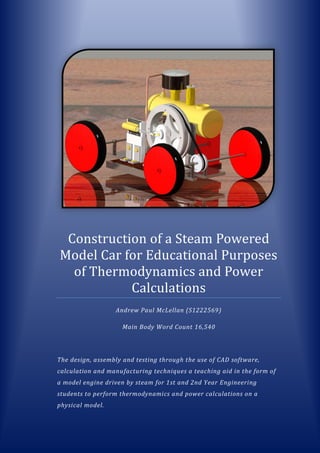
  • 1. Construction of a Steam Powered Model Car for Educational Purposes of Thermodynamics and Power Calculations Andrew Paul McLellan (S1222569) Main Body Word Count 16,540 The design, assembly and testing through the use of CAD software, calculation and manufacturing techniques a teaching aid in the form of a model engine driven by steam for 1st and 2nd Year Engineering students to perform thermodynamics and power calculations on a physical model.
  • 2. i Abstract The aim of this project was to create a teaching aid that would be a useful tool for lecturers of Thermodynamics and Engineering Design and Analysis. The thought behind this being that testing of a physical model could help consolidate theory learned in lectures and tutorials providing students with a better understanding of the applications of what they have learned in the classroom. This was achieved through the design, manufacture and testing of a model engine powered by a pressurised vessel containing steam. With applications for thermodynamics calculations, and engine torque and power calculations, a small steam engine provided a wide-range of applications for the lecturer to relate to the curriculum. The engine was taken from the initial design stage with different engine concepts considered before deciding on the most suitable design due to a variety of factors. These components were created using computer aided design software and where then manufactured using a variety of manufacturing methods in the university engineering applications workshop. These included 3-axis machining and 3D rapid prototyping techniques. With the completion of component manufacturing, the assembly and testing of the engine was then undertaken. All tests conducted had a high emphasis on safety due to the nature of the model’s intended environment of application. Numerous steps were taken throughout the various sections of the testing phase to ensure personal safety and to make the system as safe as possible to handle. These included performing hand calculations to validate the boiler design and material in conjunction with computer aided finite element analysis. It also entailed abiding to British Standards for pressure vessel testing and the completion of risk assessments for use of naked flame heat sources and a pressurised vessel in an educational environment. With results and testing being a success a study of possible applications and apparatus needed to perform these experiments was constructed. The result of this was the foundation of potential lesson plans a lecturer could create that could be carried out by the student.
  • 3. ii Acknowledgements Special thanks to my project supervisor David Ross on feedback and advice given throughout the year and being available for me to arrange meetings whenever I had questions about the direction of my project. A huge thanks to technicians Ian Hamilton and Derek Leitch for putting up with my daily visits and holding you back from your lunch and coffee breaks with my project. Your input in helping to solve problems that cropped up on a weekly basis with construction was invaluable. Thank you to Colin Russell of the Chemistry Department for welcoming an outsider into your department to conduct experiments deemed too dangerous to perform anywhere else. To Colin Dalglish I extend my gratitude for the incredibly quick turnaround of 3D printed components every time I needed a new part made and for answering almost every email within the same minute of me sending them. A final thank you to my university colleagues, friends, family and to my girlfriend for putting up with my absence during long days and nights in the library.
  • 4. iii Table of Contents Abstract............................................................................................................................i Acknowledgements..........................................................................................................ii Table of Contents............................................................................................................ iii List of Figures................................................................................................................. vii Tables........................................................................................................................... viii Nomenclature................................................................................................................. ix Glossary.......................................................................................................................... ix 1 Introduction .............................................................................................................1 2 Literature Review .....................................................................................................3 2.1 Historical Introduction to Using Steam for Work ......................................................3 2.2 Laws of Thermodynamics ..........................................................................................5 2.2.1 Steam .................................................................................................................5 2.2.2 Heat Engines and Second Law of Thermodynamics ..........................................5 2.3 How a Steam Engine Works.......................................................................................8 2.3.1 Engine Overview ................................................................................................8 2.3.2 Cylinder ..............................................................................................................8 2.4 Various Cylinder Designs............................................................................................9 2.4.1 Double Acting Stationary Engine Cylinder .........................................................9 2.4.2 Oscillating Cylinder Design...............................................................................10 2.4.3 Uniflow (Unaflow) Engine................................................................................10 2.5 Boiler Design/Efficiency ...........................................................................................11 2.5.1 Safety Relief Valves..........................................................................................11 2.5.2 Efficiency..........................................................................................................12 2.5.3 Boiler Types......................................................................................................13 2.6 Manufacturing Methods..........................................................................................14 2.6.1 Cylinder and Piston ..........................................................................................14 2.6.2 Boiler................................................................................................................14 2.6.3 Flywheel...........................................................................................................15 2.7 Teaching Techniques................................................................................................16 2.7.1 Lectures............................................................................................................16 2.7.2 Tutorials ...........................................................................................................16 2.7.3 Labs ..................................................................................................................16 2.8 Corresponding British Standards .............................................................................17
  • 5. iv 3 Methods................................................................................................................. 18 3.1 Design Process .........................................................................................................18 3.1.1 Component Design...........................................................................................19 3.1.2 Flywheel...........................................................................................................19 3.1.3 Crank ................................................................................................................20 3.1.4 Flywheel Mount ...............................................................................................20 3.1.5 Boiler................................................................................................................21 3.1.6 Firebox .............................................................................................................22 3.1.7 Piston, Cylinder and Port Face.........................................................................22 3.1.8 Model Car Chassis............................................................................................23 3.2 Manufacture ............................................................................................................25 3.2.1 Machining (3-Axis) ...........................................................................................25 3.2.2 Rapid Prototyping ............................................................................................28 Fabrication .......................................................................................................................30 3.2.3 Lathe ................................................................................................................33 3.3 Construction.............................................................................................................35 3.3.1 Mounting the Flywheel....................................................................................35 3.3.2 Boiler Threaded Connections...........................................................................36 3.3.3 Synchronisation of Cylinder/Piston..................................................................36 3.3.4 Component Placement ....................................................................................37 3.3.5 Component Redesign.......................................................................................37 4 Testing ................................................................................................................... 39 4.1 Analytical Calculations for Boiler .............................................................................39 4.1.1 Working Pressure (15psi).................................................................................41 4.1.2 Factor of Safety Pressure (45psi) .....................................................................41 4.2 Analysis of Boiler with Ansys Software....................................................................43 4.2.1 Working/Destructive Pressure Testing ............................................................43 4.3 Testing of Heat Sources on Boiler............................................................................46 4.3.1 Fuel Types ........................................................................................................46 4.3.2 Test Outline......................................................................................................47 4.3.3 Risk Assessment...............................................................................................48 4.3.4 Execution of Test..............................................................................................48 4.4 Pressure Testing of Boiler ........................................................................................51 4.5 Full Engine Model Tests ...........................................................................................52 4.5.1 Synchronisation of Oscillating Cylinder, Piston and Crank ..............................52
  • 6. v 4.5.2 Stationary Test.................................................................................................53 4.5.3 Test on Model Car Chassis ...............................................................................54 4.5.4 Engineering Calculations from Stationary Model............................................54 5 Results ................................................................................................................... 54 5.1 Design.......................................................................................................................54 5.2 Manufacture ............................................................................................................56 5.3 Assembly..................................................................................................................57 5.3.1 Sub-Assembly...................................................................................................57 5.3.2 Full Assembly ...................................................................................................58 5.4 Testing......................................................................................................................59 5.4.1 Ansys Pressure Testing.....................................................................................59 5.4.2 Physical Testing................................................................................................59 6 Discussion .............................................................................................................. 60 6.1 Part Design...............................................................................................................60 6.1.1 Flywheel...........................................................................................................60 6.1.2 Flywheel Mount ...............................................................................................61 6.2 Tolerances................................................................................................................62 6.3 Attaching the V Belt.................................................................................................63 6.4 Acquiring Suitable Components...............................................................................64 6.5 Manipulation of Steam Flow....................................................................................65 6.6 Possible System Tests ..............................................................................................66 7 Further Work.......................................................................................................... 68 7.1 Boiler Efficiency........................................................................................................68 7.2 Convection Analysis .................................................................................................68 7.3 Manufacture of All Components .............................................................................69 7.4 Inclusion of Electronics and Electrical Components................................................70 7.4.1 RC Capability ....................................................................................................70 7.4.2 Obstacle Avoidance..........................................................................................70 7.4.3 Flywheel Connection to Dynamo.....................................................................71 7.5 Closed System (Rankine Cycle Design).....................................................................71 7.6 Masters Project........................................................................................................72 8 Conclusion.............................................................................................................. 73
  • 7. vi 9 References ............................................................................................................. 74 10 Appendices............................................................................................................. 80 10.1 Appendix A - PTC Creo Pro-Engineer Component Designs......................................80 10.1.1 Piston ...............................................................................................................80 10.1.2 Copper Piping...................................................................................................80 10.1.3 Flywheel...........................................................................................................80 10.1.4 Cylinder ............................................................................................................81 10.1.5 Flywheel Mount ...............................................................................................81 10.1.6 Crank ................................................................................................................81 10.1.7 Firebox .............................................................................................................82 10.1.8 Chassis..............................................................................................................82 10.1.9 Rear Axle Sub-Assembly...................................................................................83 10.1.10 Engine Final Assembly......................................................................................83 10.2 Appendix B – Ansys Pressure Testing Results..........................................................84 10.2.1 Pressure Test 15psi ..........................................................................................84 10.2.2 Pressure Test 45psi ..........................................................................................95 10.3 Appendix C – Manufacture ....................................................................................107 10.3.1 Dugard Technical Information .......................................................................107 10.3.2 ProJet 1000 Technical Information................................................................108 10.4 Appendix D - Rod End Bearing Technical Information...........................................108 10.5 Appendix E - Flanged Bearing Technical Information............................................109 10.6 Appendix F - Safety Relief Valve Technical Information........................................109 10.7 Appendix G - Pressure Gauge Technical Information............................................110 10.8 Appendix H - Testing/Evaluation ...........................................................................110 10.9 Appendix I - Boiler Material Data Sheet ................................................................110 10.10 Appendix J - Analysis of Boiler with Ansys Software .........................................113 10.11 Appendix K - Heat Sources Data Sheets.............................................................113 10.11.1 (Hexamine Solid Fuel) ....................................................................................113 10.11.2 (Methylated Spirit Liquid Fuel) ......................................................................117 10.12 Appendix L -Hydraulic Pump Data Sheet ...........................................................120 10.13 Appendix N - Risk Assessment for Pressure Testing..........................................131 10.14 Appendix O - BS ISO 16528-1:2007 (Testing Section)........................................138 11 Bibliography......................................................................................................... 140
  • 8. vii List of Figures FIGURE 2-1 NEWCOMEN ENGINE (THE TRANSCONTINENTAL RAILROAD, 2012)........................................................3 FIGURE 2-2THEVITHICK'S HIGH PRESSURE TRAM ENGINE (THE TRANSCONTINENTAL RAILROAD, 2012) ........................4 FIGURE 2-3-A PLOT OF TEMPERATURE VERSUS ENERGY ADDED WHEN A SYSTEM INITIALLY CONSISTING OF 1.00 G OF ICE AT 230.0Β°C IS CONVERTED TO STEAM AT 120.0Β°C. (SERWAY& JEWETT JR, 2014 PG599)....................................5 FIGURE 2-4CARNOT (IDEAL) HEAT CYCLE (P/V) & (T/S), (ELECTROPEDIA, 2005) ....................................................6 FIGURE 2-5 OTTO HEAT CYCLE (P/V) & (T/S), (ELECTROPEDIA, 2005)..................................................................7 FIGURE 2-6 – SIMPLE DIAGRAM OF A RECIPROCATING STEAM ENGINE (HOW A STEAM ENGINE WORKS, 2011) ............8 FIGURE 2-7 - DIAGRAMMATIC AND PERSPECTIVE SECTION OF CYLINDER, PISTON AND CONNECTED SLIDE VALVE (WILLIAMS, 2009, P. 12)......................................................................................................................9 FIGURE 2-8 DOUBLE ACTING STATIONARY CYLINDER STAGES OF ACTION IN THE CYLINDER (BRITANNICA ONLINE, 2012) .9 FIGURE 2-9 LABELLED DIAGRAM OF OSCILLATING CYLINDER DESIGN (MARTIN, 2007).............................................10 FIGURE 2-10 SCHEMATIC OF COMPRESSION AND EXPANSION IN A UNIFLOW ENGINE (WIKIPEDIA, 2016) ................10 FIGURE 2-11 HOW A SPRING LOADED SAFETY RELIEF VALVE FUNCTIONS...............................................................11 FIGURE 2-12 COMPARISON OF WATERTUBE BOILER AND FIRETUBE BOILER (HOW STUFF WORKS, 2008) ...................13 FIGURE 2-13 DEEP DRAWING MANUFACTURING PROCESS..................................................................................14 FIGURE 2-14 DIE CASTING MANUFACTURING METHOD .....................................................................................15 FIGURE 2-15 EXAMPLE OF TESTING THAT COULD BE CARRIED OUT BY STUDENTS ....................................................17 FIGURE 3-1 STEPS TAKEN FOR METHODS USED IN PROJECT ................................................................................18 FIGURE 3-2 STEPS TAKEN FOR FLYWHEEL DESIGN ON PRO ENGINEER....................................................................19 FIGURE 3-3 STEPS TAKEN FOR CRANK DESIGN ON PRO ENGINEER ........................................................................20 FIGURE 3-4 STEPS TAKEN FOR FLYWHEEL HOUSING DESIGN ON PRO ENGINEER ......................................................20 FIGURE 3-5 STEPS TAKEN FOR BOILER DESIGN ON PRO ENGINEER........................................................................21 FIGURE 3-6 STEPS TAKEN FOR FIREBOX DESIGN ON PRO ENGINEER ......................................................................22 FIGURE 3-7 CAD REPRESENTATION OF FINISHED PORT FACE BLOCK WITH ATTACHED COMPONENTS ..........................23 FIGURE 3-8 3 STEPS TAKEN FOR MODEL CAR CHASSIS DESIGN ON PRO ENGINEER ..................................................24 FIGURE 3-9 ENGINE CHASSIS SUB ASSEMBLY....................................................................................................24 FIGURE 3-10DUGARD HSM 600 SET FOR 3 AXIS MILLING AND SIEMENS CONTROLLER............................................25 FIGURE 3-11 COMPARISON OF AXIS BETWEEN 3 AND 5 AXIS (CNC COOKBOOK INC., 2015) P.15,17........................26 FIGURE 3-12 COMPARISON OF TOOL SELECTION BETWEEN 3/5-AXIS TO EXPRESS SAME RESULT................................26 FIGURE 3-13 ALUMINIUM BLOCK PREPARED FOR MACHINING AND AFTER MACHINING OF TOP SIDE OF FLYWHEEL.......27 FIGURE 3-14 LAYOUT OF STEREOLITHOGRAPHIC 3D PRINTER (ADDITIVELY, 2013)..................................................28 FIGURE 3-15 RAPID PROTOTYPE CONSTRUCTION OF FLYWHEEL MOUNT USING PROJET 1000...................................29 FIGURE 3-16 CONCEPT CRANK AND FINAL FINISHED CRANK CREATED WITH PROJET 1000 .......................................30 FIGURE 3-17 DEEP DRAWING METHOD ..........................................................................................................31 FIGURE 3-18 PURCHASED MAMOD SE3 BOILER ...............................................................................................31 FIGURE 3-19 FINISHED FABRICATED FIREBOX STAINLESS STEEL ............................................................................32 FIGURE 3-20 SMALL JIG WITH THREADED END TO ATTACH FLYWHEEL IN POSITION TO BE CUT BY THE LATHE. ...............33 FIGURE 3-21 CUTTING OF CENTRE 6MM X 2.5MM CHANNEL OF THE FLYWHEEL WITH A LATHE..................................33 FIGURE 3-22 FINISHED PISTON AND CYLINDER..................................................................................................34 FIGURE 3-23 ENGINE COMPONENTS UNASSEMBLED..........................................................................................35 FIGURE 3-24 5 X 10 X 4MM FLANGED BEARING ...............................................................................................35 FIGURE 3-25 FLYWHEEL MOUNTING SUB-ASSEMBLY.........................................................................................36 FIGURE 3-26 BOILER PLUGS FOR PRESSURE TESTING .........................................................................................36 FIGURE 3-27 MOVING PARTS OF OSCILLATING PISTON AND CYLINDER DESIGN WITH CONNECTED CRANK ....................37 FIGURE 4-1 ALPHA BRASS.............................................................................................................................39 FIGURE 4-2 BOILER DIMENSIONS FOR THIN CYLINDER CALCULATIONS ...................................................................40 FIGURE 4-3 APPLICATIONS OF FINITE ELEMENT ANALYSIS ...................................................................................43 FIGURE 4-4 BOILER WITH INTERNAL PRESSURE OF 15PSI SHOWING VON MISES EQUIVALENT STRESS ..........................45 FIGURE 4-5 15PSI INTERNAL PRESSURE RESULT IN 1.2E+033(0.5 AUTO) TO EXAGGERATE DEFORMATION........... ERROR! BOOKMARK NOT DEFINED. FIGURE 4-6 SOILD FUEL (THE PREPARED GUY, 2015)........................................................................................46 FIGURE 4-7 LIQUID FUEL (THE PAINT SHED, 2016)...........................................................................................46 FIGURE 4-8 ENVAIR VACUUM HOOD ..............................................................................................................48
  • 9. viii FIGURE 4-9 METHYLATED SPIRITS TEST WITH THERMAL IMAGE DISPLAYING IGNITION TEMPERATURE OF HEAT SOURCE APPLIED TO BOILER.............................................................................................................................49 FIGURE 4-10 SOLID HEXAMINE FUEL TEST WITH THERMAL IMAGE DISPLAYING IGNITION TEMPERATURE OF HEAT SOURCE APPLIED TO BOILER.............................................................................................................................49 FIGURE 4-11 HEAT SOURCE TRAY DURING TEST VS AFTER REDESIGN....................................................................50 FIGURE 4-12 PRESSURE TESTING OF BOILER.....................................................................................................51 FIGURE 4-13 CRANK POSITION VS CYLINDER AXIAL MOVEMENT ..........................................................................52 FIGURE 4-14 MODEL RUNNING ON COMPRESSED AIR AT 15PSI WITH NO BELT ATTACHED TO REAR AXLE ...................53 FIGURE 5-1 FINISHED MODEL ISOMETRIC VIEW ................................................................................................54 FIGURE 5-2 FINISHED MODEL TOP VIEW HIGHLIGHTING PATH OF COPPER PIPE......................................................55 FIGURE 5-3 FINISHED MODEL REAR VIEW SHOWING BOTH FLYWHEELS ARE IN LINE ................................................55 FIGURE 6-1 INCLUSION OF GRUB SCREW INTO FLYWHEEL DESIGN ........................................................................60 FIGURE 6-2 FLYWHEEL MOUNT SUPPORTING FLYWHEEL ON ONE SIDE ONLY..........................................................61 FIGURE 6-3 ROD BEFORE AND AFTER KNURLING TECHNIQUE USED TO INCREASE ROD DIAMETER ...............................62 FIGURE 6-4 ALLIGATOR BELT FASTENER...........................................................................................................63 FIGURE 6-5 PILLOW BLOCK AND ROD END BEARING..........................................................................................64 FIGURE 6-6 DIFFERENCE IN BELT ANGLE BETWEEN PILLOW BLOCK AND ROD END BEARINGS WITH REGARDS TO CHASSIS 65 FIGURE 7-1 MODEL FIRETUBE BOILER THAT WOULD INCREASE BOILER EFFICIENCY (GIANDOMENCIO, 2011)...............68 FIGURE 7-2 CONVECTION ANALYSIS OF A FIRETUBE BOILER USING FEA SOFTWARE (COSMOL, 2016) ........................69 FIGURE 7-3 RADIO CONTROLLED FRONT AXLE FOR TURNING FRONT WHEELS (RED RC NETWORK, 2009)...................70 FIGURE 7-4 INFRARED SENSORS ATTACHED TO RC CAR CONTROLLED BY ARDUINO MICROCONTROLLER (PEER, 2015)...70 FIGURE 7-5 RANKINE CYCLE (TRANSPACIFIC ENERGY, INC, 2016) ........................................................................71 Tables TABLE 1 STEPS OF CARNOT CYCLE ....................................................................................................................6 TABLE 2 STEPS OF OTTO CYCLE ........................................................................................................................7 TABLE 3 MATERIAL PROPERTIES OF BOILER FOR FEA SIMULATION (CES EDUPACK, N.D.) .........................................44 TABLE 4 COMPONENT MANUFACTURING PROCESSES .........................................................................................56 TABLE 5 RESULTS FROM ANSYS PRESSURE VESSEL TESTING .................................................................................59
  • 10. ix Nomenclature Abbreviation Meaning CAD Computer Aided Design FEA Finite Element Analysis RPM Revolutions per minute BS British Standard CNC Computer Numerical Control BSP British Standard Pipe BSF British Standard Fine SL Stereolithography, type of 3D printing RC Radio Controlled PSI Pounds per Square Inch MPa Mega Pascals Glossary Word/Phrase Meaning Entropy(S) A measure of Molecular Disorder within a macroscopic system. Isothermal An isothermal process is a change of a system, in which the temperature remains constant. Adiabatic When a gas is compressed under adiabatic conditions, its pressure increases and its temperature rises without the gain or loss of any heat. Rapid Protoyping Rapid prototyping is a group of techniques used to quickly fabricate a scale model of a physical part or assembly using three- dimensional computer aided design data. PTC Creo/ProEngineer Computer Aided Design Software Ansys Finite Element Analysis Software Factor of Safety (FOS) Capacity of a system beyond the expected loads or actual loads. Von Mises Equivalent Stress Used to validate whether a design can withstand a given load condition Youngs Modulus A measure of elasticity, equal to the ratio of the stress acting on a substance to the strain produced. All symbols used in this report are sufficiently labelled throughout.
  • 11. 1 1 Introduction In the engineering sector, it has been recognised that there is a considerable jump that many find difficult between university and the workplace. Applying what students have learned at university to real life situations that arise while working in the field of engineering is sometimes one that requires a lot of supervision by the employer. On numerous courses students leave university having had minimal, if any, exposure to practical experience in an engineering working environment either through placements or university. The resultant costs of this ultimately being picked up by the employer by needing to give the graduates extra training to meet the required company standards. This gap in practical familiarity also limits the responsibility that can be given to graduates early in their career as it hinders the progress an entry level engineer can make before becoming an experienced engineer. This lack in familiarity is fundamentally down to the fact that many students do not recognise how considerable portions of the curriculum they have spent the last 4/5 years of their academic career attaining relates to real problems in industry. Students can be told by a lecturer how a certain topic they are learning is used in a variety of applications. But unless these applications can be attempted through the use of engineering tools relating the problem to examples faced in industry it is likely not all students will grasp what the lecturer is trying to explain. The problem lies not with what they have been taught but that it could be taught in a way that is more effective in helping the student to understand why this rule or technique is used. It has been shown in studies that graduates with relevant industrial experience and a good classification of degree have a better chance of getting a job than someone with a better classification with no experience. In a study by the Independent Newspaper figures show that 58 per cent of employers rated work experience as β€œthe most popular qualification among those presented” (Garner, 2015)Although it cannot be expected by industry to accommodate every student with industrial experience, this is where universities should be able to help make up for this unavoidable shortfall. A survey carried out by YouGov in 2013 consisting of 635 employers showed that β€œjust 19 per cent of business leaders said all or most graduate recruits were work-ready.” (Paton, 2013) Giving students real practical problems on working models using techniques which have common ground with industry can help create more overlap better preparing students for the transition to the workplace. It is common practice for some students to be able to study for exams, pass and progress onto the next level without any real awareness as to how the problems they solved in their
  • 12. 2 exam are used outside of the classroom. Many universities offering engineering courses focus solely on the classroom and theory side of engineering which is extremely important. However, it is being able to put across what students have learned in the classroom by appropriately relating it to problems faced in the engineering environment that is most important for student understanding. This is where the use of practical teaching aids to supplement learning comes into play. Using a physical model relating to the problem faced helps students identify why the course content is relevant to their learning and potential careers. It also helps create a groundwork going forward that a student can look back to and relate to future problems they may come across. Working with this idea, the central aim of this dissertation was to create a working model of a steam powered model car that can be used as a teaching aid for basic thermodynamics and engineering principles across various modules. The project will consist of working from the initial design stage of this engine using CAD software packages for component design and analysis and for safety testing of components to ensure it is suitable for the teaching environment. The model components will be created in the workshop using a variety of different manufacturing techniques then be assembled. The constructed model will then have certain high stress components tested separately before performing tests of the overall system to ensure it is running correctly and safely as designed. After the finished model has been deemed safe and running correctly from the evidence collected in the test phase it will advance to the creation of possible lesson plans. These lesson ideas will focus on the applications in areas of Thermodynamics and Engineering Design and Analysis. It will outline apparatus that can be used in conjunction with the model to gather data to perform suitable calculations. There will then be a discussion section which will evaluate what the project has achieved and its viability as a suitable teaching aid. The discussion will be followed by a section on further work that could be investigated to further develop this model. And by doing so, making it a more valuable piece of equipment for the university. This project gives an example of how models can be used to aid teaching and consolidate learning early in student academic careers at university studying engineering.
  • 13. 3 2 Literature Review 2.1 Historical Introduction to Using Steam for Work The steam engine is regarded by historians to be one of the most ground breaking inventions of the modern age. This invention was the earliest example of a source able to provide power regardless of weather, location or having to rely on the work of animals (Lovland, 2007, p. 1). Though it had been touched on by many as the understanding of what the atmosphere itself grew it was not until the early 1700s any real progress was made within the design of the modern steam engines recognised today. Up to this point steam had only been used in the way of a small pump designed by Thomas Savery in which he created a vacuum which would provide a pressure resulting in pushing water upwards. This design invented by Savery in 1698 consisted of 3 valves, a boiler, condensing chamber and was connected by tubes allowing water to be pumped upwards. Another inventor who when faced with a problem that was solved by revisiting Savery’s early design was Thomas Newcomen. The problem faced by Newcomen was to come up with an alternative to using horses to keep pumping water out from larger mines that were flooding as using horses was becoming very expensive due to the number that were needed. By using points from Savery’s Pump as a starting point Newcomen was able to invent in its simplest form the first atmospheric engine. (Dickinson, 1939, pp. 29-53). Although his engine was somewhat inefficient and start-up costs too expensive as an alternative for many mine owners it was a significant step closer to the steam engine that is held in high regard when looking back at how it has evolved since the late 1600s. It was in the 17&1800s that vast improvements were made on design and efficiency of the early steam engine and the realisation that this system could be applied to other areas of industry than just water pumps. (Lovland, 2007, p. 5) James Watt, the Engineer responsible for developing the concept of horsepower as a universal measurement of power, made a considerable contribution to the development of the steam engine by further improving inefficiencies in Newcomen’s designs. Many accept James Watt to be the inventor of the steam engine but with some research it is evident that he made large ground-breaking improvements and Figure 2-1 Newcomen Engine (The Transcontinental Railroad, 2012)
  • 14. 4 expansions on existing designs rather than conceptualising from its beginning. Even though his design was manufactured and used in the 1700s after huge investment, this was only in Great Britain and very few steam engines could have been found anywhere else until the mid-1800s due to Britain’s booming Industrial Revolution (Dickinson, 1939). And as Watt engines became more readily available as mechanical sources of work the industrial power of the British Empire only grew and so did the country’s wealth. (Griffin, 2010) By looking back at how much of an effect being able to harness steam power had it is evident the impact that it had in terms of industrial progress in the late 1800s was huge. With later designs by Richard Trevithick and then William McNaught incorporated further applications into areas such as transportation on land and at sea its effect was profound and it changed these areas forever paving the way for further advancement and more efficient engines as the decades went on. (Hills, 2004) Figure 2-2Thevithick's High Pressure Tram Engine (The Transcontinental Railroad, 2012)
  • 15. 5 2.2 Laws of Thermodynamics 2.2.1 Steam When looking at using steam as work the laws of thermodynamics are of vital importance in calculating and understanding properties of steam. Since the engine for this project is using steam from water as a way of creating pressure within a cylinder to produce work it is vital that an understanding of how water’s state varies with temperature. For a steam engine the water only becomes useful when it is steam and when this is stored in a sealed pressurised vessel it will boil at a higher temperature therefore its pressure can be increased above atmospheric pressure making for a high steam output making the engine more powerful. (Serway & Jewett Jr, 2014) Figure 2-3-A plot of temperature versus energy added when a system initially consisting of 1.00 g of ice at 230.0Β°C is converted to steam at 120.0Β°C. (Serway& Jewett Jr, 2014 Pg599) 2.2.2 Heat Engines and Second Law of Thermodynamics The application of heat engines are systems that convert heat energy from an external source through a cyclic process in turn ejecting a portion of this energy into workable kinetic energy. During this process for steam engines in particular the water in the boiler absorbs energy in the way of heat evaporating into steam and uses this to push a piston. The fundamental limit is known as the Carnot limit where in an ideal heat engine it would convert all heat energy into workable mechanical energy as shown in the graph of an ideal Carnot Cycle below.
  • 16. 6 Figure 2-4Carnot (Ideal) Heat Cycle (P/V) & (T/S), (Electropedia, 2005) Table 1 Steps of Carnot Cycle Change of State Carnot Heat Cycle Processes A – B β€œReversible isothermal compression of the cold gas. Isothermal heat rejection. Gas starts at its "cold" temperature. Heat flows out of the gas to the low temperature environment. B – C Reversible adiabatic compression of the gas. Compression causes the gas temperature to rise to its "hot" temperature. No heat gained or lost. C - D Reversible isothermal expansion of the hot gas. Isothermal heat addition. Absorption of heat from the high temperature source. Expanding gas available to do work on the surroundings (e.g. moving a piston). D - A Reversible adiabatic expansion of the gas. The gas continues to expand, doing external work. The gas expansion causes it to cool to its "cold" temperature. No heat is gained or lost.” (Electropedia, 2005) β€œThe maximum (or "theoretical") efficiency of any heat engine is described in terms of the temperatures of the heat source and heat sink. Temperatures are expressed in the Kelvin scale (Celsius + 273).” (Berger, 2001) π‘‡β„Žπ‘’π‘œπ‘Ÿπ‘’π‘‘π‘–π‘π‘Žπ‘™ 𝐸𝑓𝑓𝑖𝑐𝑖𝑒𝑛𝑐𝑦 = π‘‡β„Žπ‘œπ‘‘ βˆ’ π‘‡π‘π‘œπ‘™π‘‘ π‘‡β„Žπ‘œπ‘‘ Γ— 100% However, there are many inefficiencies within these systems, with none ever having 100% efficiency when compared to the theoretical Carnot engine. This is due to a variety of causes: ο‚· Transfer of Heat from Heat Source ο‚· Frictional Forces ο‚· Energy losses by conduction ο‚· Energy Lost through Sound ο‚· Change in entropy Due to these factors indicated the cycle that would be considered most suitable to describe a steam engine would be the Otto Cycle.
  • 17. 7 Figure 2-5 Otto Heat Cycle (P/V) & (T/S), (Electropedia, 2005) Table 2 Steps of Otto Cycle Change of State Otto Heat Cycle Processes A – B β€œCompression Stroke. Adiabatic compression of air / fuel mixture in the cylinder B – C Ignition of the compressed air / fuel mixture at the top of the compression stroke while the volume is essentially constant. C - D Expansion (Power) Stroke. Adiabatic expansion of the hot gases in the cylinder. D - A Exhaust Stroke Ejection of the spent, hot gases. Induction Stroke Intake of the next air charge into the cylinder. The volume of exhaust gasses is the same as the air charge.” (Electropedia, 2005)
  • 18. 8 2.3 How a Steam Engine Works 2.3.1 Engine Overview In the figure below the diagram shows the main parts of a single cylinder reciprocating steam engine in its simplest form. It shows water in the form of steam being pushed through and into the cylinder pushing the piston forward. When the piston is fully extended it allows the steam that has pushed it forward to escape allowing atmospheric pressure to be achieved in the cylinder before the mechanical work that has turned the flywheel from the steam pushes the piston back in the cylinder closing off the gas escape valve therefore creating pressure again in the cylinder to repeat the process. This cycle is what keeps this engine running on the power of the pressure built up in the cylinder with steam allowing for the heat energy to be converted into more useful mechanical energy. (Serway & Jewett Jr, 2014) As this system is not a closed system it will eventually run out of workable steam when the water from the boiler has all been exhausted unlike a closed system that would continue to run until the heat source stopped heating the boiler. Figure 2-6 – Simple Diagram of a Reciprocating Steam Engine (How A Steam Engine Works, 2011) 2.3.2 Cylinder The key to the steam engine’s reciprocating process is what happens within the cylinder. The diagram of the cylinder below shows that the steam is injected into the steam chest where it is directed by the slide valve to enter the cylinder. The valve rod is controlled by the previous mechanical work done by the engine which covers and exposes the left injection valve allowing the steam to pressurise the cylinder pushing the piston forward till the valve is opened allowing for the pressure to be released. This is part of the engine is what is doing the work and replacing the need for physical work by the human body. The linear cyclical motion produced in the cylinder is converted into a rotary motion by the connected driving rod and crank that turns a weighted flywheel. (Williams, 2009, p. 12)
  • 19. 9 Figure 2-7 - Diagrammatic and Perspective Section of Cylinder, Piston and Connected Slide Valve (Williams, 2009, p. 12) 2.4 Various Cylinder Designs In the case of model steam engines - the focus of this project - there are various designs that can be taken as a basis for the design of the engine to be used in this project. The main point of difference on many of the model designs is the three main types of piston and cylinder. 2.4.1 Double Acting Stationary Engine Cylinder This cylinder design as described in the previous section is the more common of the two cylinder designs. This design has a steam chest attached in which the steam is directed to either the left or right side of the cylinder by the sliding valve. This sliding valve works in synchronisation with the cylinder and piston and is done so through and eccentric rod attached to the flywheel so both the cylinder and sliding valve work at the same rpm. From the diagram the cylinder has steam pushed in from the left pushing the piston right. This work done from the steam pushing the piston left turns the flywheel which connected to the eccentric rod slides the sliding D valve exposing the exhaust port allowing the steam to escape. When the left side of the cylinder is exposed to the exhaust port the steam is then directed into the right side of the cylinder pressurising it therefore pushing back in the left direction. This process, when repeated, makes up the reciprocating motion needed to turn the flywheel and creates kinetic energy. Figure 2-8 Double Acting Stationary Cylinder Stages of Action in the Cylinder (Britannica Online, 2012)
  • 20. 10 2.4.2 Oscillating Cylinder Design This variant of cylinder design is one that does not require valves or the addition of an eccentric crank. The cylinder is instead held in place by a pivot (trunnion) that on which the entire cylinder is able to oscillate back and forth. It is when performing this motion that the hole in the cylinder lines up with the holes in the port face that inject and exhaust the steam traveling from the boiler. As the cylinder lines up with the steam hole steam flows into the cylinder expanding and pushing forward the piston. As the crank rotates the cylinder rocks on the x-axis until it lines up with the exhaust port expelling the steam. The process then repeats. This design is rarely used full scale and is mostly used in models due to its simplicity. This design in order to cycle properly needs to be lined up at the same height as the flywheel and placed in a position that allows for the piston to have a full range of movement through the length of the cylinder. (World Heritage Encyclopedia, 2002) Figure 2-9 Labelled Diagram of Oscillating Cylinder Design (Martin, 2007) 2.4.3 Uniflow (Unaflow) Engine This particular type of steam engine uses the steam to push the piston past half way in the cylinder which in turn exposes the exhaust port located in the centre of the cylinder. There are two poppet valves controlled by a rotating camshaft that work in relation to which side the steam enters the cylinder. When the exhaust port is exposed on one side it pushes the piston past half way and closes the flow of steam to this side and pushes the steam through the other poppet valve pushing the piston back until the exhaust port is exposed from the opposite direction. From the diagram below high pressure steam enters the cylinder (red) and exhausts after full expansion which exposes the exhaust port (yellow). Figure 2-10 Schematic of Compression and Expansion in a Uniflow Engine (Wikipedia, 2016)
  • 21. 11 2.5 Boiler Design/Efficiency The boiler is a crucial part of how the overall engine performs as this is the source of the engines power. There have been various boiler designs for steam engines depending on the application and heat source available to boil the water. When designing a boiler there are several factors that must be taken into account in order for it to be fit for purpose. The aspects that must be adhered to for model steam engine boilers in order for them to be considered to be an acceptable design consist of: 1. Conformity to Safety UK Standards, Regulations and Considerations 2. Suitable Material for quality of water being used. 3. Calculated Design Pressures and Temperatures 4. Type of Heat Source from which the steam will be created. 5. Capacity of Steam Output Needed for Engine to function at determined Power. 6. Cost of Material Constraints. (HSE, 2000, p. 25) 2.5.1 Safety Relief Valves A suitable safety relief valve would also be added once the boiler has been designed as another method to ensure safety while the boiler is pressurised and performing at the boiler’s determined working pressure. It works by automatically not allowing the boiler system to go above the intended pressure of the boiler by releasing excess steam bringing the pressure back down to within the intended safe limits. Most common type of safety valve in the application of model steam engines is the spring loaded safety valve. This valve works by having a spring of a certain compressive strength inserted into the valve housing. The compressive strength of this spring is what affects at what pressure the valve with release opening the value allowing steam to escape. This will in turn bring the pressure of the boiler back down below the pressure needed to set off the relief valve, the working pressure. Figure 2-11 How a Spring Loaded Safety Relief Valve Functions
  • 22. 12 2.5.2 Efficiency There are two methods used to calculate efficiency of the boiler, direct and indirect method. Direct method When using the direct method, the boiler efficiency is directly defined by the exploitable heat output from the boiler and by the fuel power of the boiler: Ξ· = Ο† π‘œπ‘’π‘‘π‘π‘’π‘‘ φ𝑖𝑛𝑝𝑒𝑑 β€œWhere Ο† π‘œπ‘’π‘‘π‘π‘’π‘‘ is the heat that is exploitable from the boiler after being heated by an external source, and φ𝑖𝑛𝑝𝑒𝑑 is the potential fuel power of the boiler if no heat escapes into the atmosphere.” (Teir & Kulla, 2002) Advantages of direct method ο‚· Boiler Efficiency can be evaluated by workers rapidly. ο‚· Instrumentation needed for monitoring is minimal. Disadvantages of direct method ο‚· Can show operator efficiency of the system but cannot specify why efficiency is lower. ο‚· Calculations do not include losses responsible for varying efficiency levels. Indirect method The indirect method defines the efficiency of a boiler by using the sum of the major losses and by fuel power of the boiler: Ξ· = 1 βˆ’ Ο†π‘™π‘œπ‘ π‘ π‘’π‘  φ𝑖𝑛𝑝𝑒𝑑 β€œWhere Ο†π‘™π‘œπ‘ π‘ π‘’π‘  is the sum of the major losses within the boiler, and φ𝑖𝑛𝑝𝑒𝑑 is the fuel power of the boiler. The indirect method provides a better understanding of the effect of individual losses on the boiler efficiency.” (Teir & Kulla, 2002) Advantages of indirect method ο‚· A complete mass and energy balance can be obtained for each individual stream, which makes it easier to identify options to improve boiler efficiency Disadvantages of indirect method ο‚· This method of efficiency calculation is more time consuming. ο‚· Due to nature of calculations this method requires lab facilities in order for analysis to be carried out. (Energy Efficiency Guide for Industry in Asia, 2006)
  • 23. 13 2.5.3 Boiler Types 2.5.3.1 Pot Boiler This type of boiler was used in the first steam engines and is by far the simplest design. The boiler consists of one hollow chamber that is partly filled with water. Heat is applied to the bottom of the tank and heats the water inside until it becomes steam which can then be used to power the engine. This type of boiler is still used today in construction of model steam engine kits as it is simplistic in design making it easy to manufacture. 2.5.3.2 Firetube With firetube boilers, heated air known as flue gases are directed through vertical or horizontal steel tubes that are surrounded by the water for heating, and typically go through a number of changes in direction depending on the boiler size. The efficiency of this boiler is an improvement when compared to a pot boiler as there is more heated surface area in contact with the water it is trying to evaporate into steam meaning it achieves producing steam quicker. 2.5.3.3 Water Tube In watertube boilers, the opposite is performed from firetubes. Instead of the water being outside the tubes, it circulates inside the tubes and is heated externally by the combustion gases within the tank. Fuel is burned inside the furnace, which heats the water in the steam- generating tubes. The water then rises to the steam drum where saturated steam is drawn from the top of the drum and used in the same application. (Johnston Boiler Company , 1995) Figure 2-12 Comparison of Watertube Boiler and Firetube Boiler (How Stuff Works, 2008)
  • 24. 14 2.6 Manufacturing Methods 2.6.1 Cylinder and Piston Pistons are usually partly manufactured using the metal cast method. Molten metal is poured into a mould in the shape of the piston and then subjected to huge pressure. Once cooled and ejected from mold the piston is prepped for secondary machining which allows for more complex parts of material removal to be completed. (Feng, et al., 2002) This process is usually used to do the finishing on the piston as to where it can be inspected and then be deemed fit for use. Secondary machining also reduces the amount of components that would possibly need to be reworked as they can be amended during the material removal in the 3/5-axis milling process. 2.6.2 Boiler When designing a boiler of a small size cold working of the chosen material is usually used. The material must be relatively malleable and not brittle to allow it to be manipulated easily. Popular materials for boilers of this size include copper, brass and steel due to their good levels of conductivity. The process of using the chosen material involves using a variety of different molds to change the shape of the material gradually from a flat piece to a hollow cylinder. This process is called deep drawing and helps strengthen the material by strain hardening as it is stretched gradually through a series of steps. The advantage to using this method is that it eliminates the need for the boiler to be welded longitudinally as it is seamless making the cylinder stronger. The wall thickness can also be reduced considerably when compared to other methods of manufacture and the surface finish is cleaner. Figure 2-13 Deep Drawing Manufacturing Process
  • 25. 15 2.6.3 Flywheel Most flywheels in industry which are still produced today for modern engines are done so through the die casting method. The metal– usually steel –heated to a liquid is injected into a mold in the shape of the flywheel under great pressure where it is held until it cools. This century old process has been modernised through use of computers allowing higher accuracy, smaller tolerances and less rework of the casting after first injection. Molds can also be made more complex by use of computers. The mold consists of two halves one with the main body cavity and the other with protrusions discounting a need for extra drilling to be done on the casting as it can be done within the mold itself. (Feng, et al., 2002) This part is kept in the mold till it cools and it is then ejected and further treated to remove burrs and flashes from the finished flywheel. This process is mostly the same with model steam engine as it is with modern car flywheels. This is with the exception of possible different choices of material depending on cost effectiveness, batch size and properties needed from the material for that particular engine design. Figure 2-14 Die Casting Manufacturing Method
  • 26. 16 2.7 Teaching Techniques When teaching engineering as a subject a variety of teaching techniques are used to give the student the best chance of understanding the course content as possible but studies have proven that some teaching techniques have more impact than others. 2.7.1 Lectures Lectures are the usually used as the point where a student will be exposed to new course material for the first time. This is the first point of contact between the lecturer and the student. Lectures are usually performed in front of large numbers of students making it a rather impersonal teaching method as it is difficult to engage will all students with student number of this size. Topics are usually presented in form of slides through power point outlining key areas of the topics including background knowledge and examples. 2.7.2 Tutorials The common practice of tutorials is to consolidate the topic areas covered within in the previous lecture. This is broken into smaller groups where students have the chance to ask questions and be given one to one feedback. The small class sizes make for a more personal style of learning where questions and potential problems can be raised with the lecturer in a less distant environment than that of a lecture. 2.7.3 Labs The use of labs gives lecturers an opportunity to display techniques to students they have learned in preceding lectures and tutorials through methods of application. This can range from, for example, performing tests on stress concentrations of thin walled steel structures to applying control systems to a working model car to verify its validity as an appropriate system for its intended purpose. This method of teaching can be very effective if proper initial guidance is given to the student and outcomes of physical testing can be appropriately linked back to current areas of teaching in lectures and tutorials. Using labs as a launch point for a module coursework that will involve students acquiring results from physical testing is a method that helps quantify the knowledge the student has gained and reinforcing their understanding. This type of teaching environment helps get students more invested in the subject area especially coursework involves students working as part of a team. This supports methods used in industry as projects are rarely ever carried out by a single person meaning not only is the student learning the course content more fully but is gaining skills by working as part of a team.
  • 27. 17 By reviewing the teaching techniques used by universities, studies have shown that a better balance of the three main teaching methods used by engineering lecturers must be given to ensure students are given the ideal opportunity to grasp the curriculum. From a study comparing exam scores of the use of active and traditional learning techniques in STEM disciplines it showed that students in classes with traditional lecturing were 1.5 times more likely to fail than students in classes with active learning. (Freeman, et al., 2014) Applying techniques learned in lectures and tutorials can improve not just student exam performance but well-rounded understanding of the subject. Figure 2-15 Example of Testing That could be Carried Out by Students 2.8 Corresponding British Standards When implementing any sort of teaching aid that is to be used to supplement learning and will be exposed to students proper standards must be adhered to. These British standards give information as to how to make the teaching environment as safe as it can possibly be with the appropriate control measures put in place. With model steam engines being classed as a pressurised vessel these items must be stored properly with correct documentation and safety checks being carried out in correspondence with Pressure Systems and Transportable Gas Containers Regulations of 1989. (Surrey County Council , 1997). This is extremely important with regards to safety as a model steam engine that does not have the proper safety checks carried out on it could have the potential of causing injury to students and lecturers. (BS4163:2014, 2014)
  • 28. 18 3 Methods In order to arrive at the final outcome which is to have a full working model of a steam engine capable of running safely in an educational environment there is numerous stages of the design process which are outlined in the diagram below. Figure 3-1 Steps Taken for Methods Used in Project 3.1 Design Process The first area in which research was carried out was into model steam engines of a similar size currently available on the market to buy as a set. The engines looked at most closely were stationary steam engines by companies Mamod and Jensen taking their designs into account when starting conceptual designs for this engine.
  • 29. 19 3.1.1 Component Design When designing all components for this steam engine the Computer Aided Design (CAD) software used was Creo Parametric 2.0. This software is an industry standard that gives the user the ability to create realistic models of their design that can be easily altered and improved as the design becomes more refined. This platform also allows for compatibility with other software that will be useful within this project such as Ansys and ProManufacture. This software also has the ability to convert files to be compatible with rapid prototype 3D printing machines, crucial for refinement throughout the project all the way to the construction and test phase if smaller parts need to be redesigned. It was decided that all components being used in the construction of the engine would be accurately designed using this software in order to provide a 3D model of the finished engine for simulation and presentation. 3.1.2 Flywheel This component was designed using Creo Parametric as the intention was to have this part machined out of aluminium as a 3D printed alternative would be too lightweight. A programme could be written using this software to produce the machine codes necessary to produce this piece using Pro-Manufacture. The outer diameter was chosen to be 105mm, a size from after research was considered suitable for a model engine of this scale. When designing this part the intention was that every part following would be designed with regards to this component’s scale. Therefore a 5mm hole was created in the centre of the flywheel in which the rod connecting it to the crank would be positioned. It was imperative at this point onwards that uniformity of parts be a main priority if the components where to be compatible with one another. A grove in the outer radius was created with the purpose of being the channel in which the belt connecting this flywheel to a smaller wheel would be positioned. The channel created was 6mm X 2.5mm giving a 5mm belt enough clearance on each side as not to cause wear from the belt touching the sides of the channel. Material was also symmetrically removed meaning it would still run smooth lower the flywheel’s weight. Figure 3-2 Steps Taken for Flywheel Design on Pro Engineer
  • 30. 20 3.1.3 Crank When designing the crank a top heavy design was chosen to give it stability at the point of contact with the rod connecting the crank to the flywheel. The top hole was made as 5mm in diameter in order to line up properly geometrically with the 5mm diameter connecting rod and centre hole of the flywheel already designed. The bottom hole was also designed as 5mm diameter to keep a uniformity of hole sizes throughout the assembly which would cut down on need for steel rods of different diameters. This bottom hole is the connection hole of the crank to the piston where the power will be delivered from the workable steam to turn the flywheel. Figure 3-3 Steps Taken for Crank Design on Pro Engineer 3.1.4 Flywheel Mount This component had many factors that had to be incorporated into its design in terms of its geometry. The main geometric issue that had to be addressed was that it had to fit the flywheel designed previously. This was done so by using the flywheel as a reference model for the construction of this component. As the centre hole of the flywheel was 5mm it was crucial that this model have a hole diameter of at least double this. This is so this hole could house bearings that could be force fitted into both holes to decrease work needed to turn the flywheel that would have been lost forces of friction. Suitable sized bearings were then be chosen with an inner diameter of 5mm to stay in line with the flywheel centre hole dimensions. Figure 3-4 Steps Taken for Flywheel Housing Design on Pro Engineer
  • 31. 21 3.1.5 Boiler With regards to the boiler design it was decided beforehand that designing I would be too complicated of a process. With the work and money needed to design and fully test a boiler in correlation with external health and safety examiners it was decided the most cost and time effective alternative would be to buy a pre-fabricated boiler. The boiler chosen would need to satisfy various numerous specifications on relative size, material selection and safety standards. The boiler chosen was a Mamod SE3 boiler used in model steam engine kits as it met all specifications. This would ensure the number of tests needed to be carried out on the boiler in order to deem it safe to use in a university environment would be minimal as it had been purposely built by a recognised model steam engine company as a pressurised vessel for holding steam. In order to include the boiler purchased in CAD assemblies of the entire system it was created to exact scale in Creo Parametric taking all measurements and placement of the 4 holes accurately straight from the physical boiler itself. When referencing technical drawings of the boiler all measurements were given in inches meaning they all had to be converted into millimetres to stay standard with all other components created. This boiler consists of a 1/8” thread hole on one side for the water filling level , two ¼” threaded holes and one threaded 3/8” hole on the top. The boiler was recreated as shown below. All dimensions where converted from inches to millimetres to keep metrics between all components constant. Figure 3-5 Steps Taken for Boiler Design on Pro Engineer It was critical that the boiler in particular be dimensionally accurate when generating it as the Creo design was to be later exported into Ansys 16.0 software to test and produce a heat mapped model of pressure and heat against time.
  • 32. 22 3.1.6 Firebox The design of the firebox was a component of significance with regards to efficiency. A tight fit would reduce heat escaping and keep the heat from the heat source concentrated on the bottom of the boiler. In order to design a firebox with this key point in mind it had to be designed to be compatible with the SE3 boiler purchased. Dimensions of the boiler were incorporated to ensure a correct length and diameter of firebox that would be a stable platform for when it is placed on top by sitting in place by the cavity on each end. In order to ensure the heat source would be supplied with sufficient oxygen four 10mm holes were created in both sides of the model to allow adequate air to flow. Figure 3-6 Steps Taken for Firebox Design on Pro Engineer 3.1.7 Piston, Cylinder and Port Face It was recognised early in the design process that there was a limit in tool sizes available that would affect manufacture of specific components. Due to the lack in availability of tools small enough for machining it was decided that both the port face and the cylinder would be purchased from a manufacturer of model steam engine parts. In order for these components to be suitable within this engine design a block was to be designed to house the port-face on which the cylinder sits at the correct height. Creating a dimensionally accurate CAD model of the purchased components would aid in the design of the block as it is easier to visualise the component being designed in relation to the purchased components in which it will have direct contact with. One of the key design points that needed to be incorporated into this part was that it needed to house the port-face hole at the exact height as the 10mm hole in the flywheel housing. This was so the full range of motion by the piston and cylinder could be achieved or else the engine would not run
  • 33. 23 effectively. The figure below illustrates an exploded view of the port-face block with the purchased components attached in the configuration they will be in on the final model. Figure 3-7 CAD Representation of Finished Port Face Block with Attached Components 3.1.8 Model Car Chassis In order to allow the steam engine to display how the engine can perform practical tasks by converting steam into mechanical work, a chassis for the finished engine to sit in had to be designed. This was the last component designed as the full finished engine had to be assembled on Pro Engineer to confirm component placement so a decision could be made as to what the dimensions of the chassis would need to be. After components were placed appropriately on the stationary plinth the chassis design was able to now be constructed as a new part. By taking measurements of the base plinth (150mm X 130mm) a suitably dimensioned cavity could be designed into which the engine would sit preventing it from moving. Once this was taken into account, the next thing that needed to be incorporated into the design was the positioning of the front and back axle and lining up the flywheel connected to the back axle with the larger flywheel. By referring to the assembly of the stationary configuration of the engine and performing hand calculations the cut out for the flywheel was properly positioned.
  • 34. 24 Figure 3-8 3 Steps Taken for Model Car Chassis Design on Pro Engineer Figure 3-9 Engine Chassis Sub Assembly
  • 35. 25 3.2 Manufacture There were a number of various manufacturing methods exploited throughout the construction of this model steam engine. Each component was studied individually taking into account its application and placement with regards to other components before making an informed decision on its chosen manufacturing process. This meant considering potential structural loads, pressures, temperatures and resistance through friction the component would likely come into contact with while running. After research and discussing the factors mentioned a material would be chosen which would most likely determine the manufacturing process. A combination of methods performed in-house and outsourced were used including machining, rapid prototyping and fabrication in order to accumulate all components required to have a finished working model. 3.2.1 Machining (3-Axis) A 3-Axis milling machine was used to manufacture a select number of components. Parts chosen to be 3-Axis machined were parts that would need to be the most hard wearing and of a suitable refined design as to be machined using the 3-Axis milling machine located in the engineering workshop. The milling machine available to use for the creation of components for this project was the Dugard HSM600, a milling machine capable of both 3-Axis and 5-Axis cutting. This particular system had been set up as a 3-Axis machine meaning suitability of models designed would need to be reviewed. The designs had to be refined several times until a model was created that would be fully compatible with the machine parameters and available tools. Figure 3-10Dugard HSM 600 set for 3 Axis Milling and Siemens Controller
  • 36. 26 Limitations With regards to this 3-Axis milling machine it allows the user to create very complex models relatively quickly and to a great accuracy. However, tool selection can sometimes limit what can be achieved with the machine with regards to models that can be created. With 3-Axis machining problems can occur with models of a large depth that require machining with tools long enough to reach the bottom of the model. This is an area in which 5-Axis machining has a much greater advantage. With the mill itself being able to rotate as the 3 axis does but also have the work piece which the model is attached to simultaneously able to roll either longitudinal or laterally on the a-b axis results in a smaller tool selection required and the opportunity to create more complex 3D models. With the 3 axis machine it requires machine code with a longer cycle time when edges need to be blended and would require further treatment and polishing when the machining process had been completed. (CNC Cookbook Inc., 2015) β€œWith a fixed spindle / tilting table configuration maximum rigidity of the tool and tool holder is achieved, whilst allowing the tool to access even the most difficult aspects of a complicated workpiece.” (Matsuura Machinery Corporation, 2009) Figure 3-11 Comparison of Axis between 3 and 5 Axis (CNC Cookbook Inc., 2015) P.15,17 Figure 3-12 Comparison of Tool Selection between 3/5-Axis to Express Same Result
  • 37. 27 Flywheel As expressed in the design section of this investigation, a suitable material for this component would need to be researched. It was key that the flywheel be heavy enough for the piston cylinder pressure but not too heavy as to where the crank would not be able to apply enough force to rotate appropriately. It was therefore decided proceed to the manufacturing stage with the material Aluminium 6082. The weight was the prevalent feature that helped in material selection as it would be heavier than a 3D printed plastic equivalent but light with regards to a carbon steel or iron equivalent. Additionally, this material was also picked due to it being purposely straightforward to machine. With regards to material properties of Aluminium 6082 although they were researched and deemed fit for purpose it was clearly evident that the application of this material for this project would come nowhere near the stresses capable of possible material deformity or maximum tensile strength and no further testing was considered to be necessary before incorporation of this component into the final engine construction. When writing the machine code the limitations expressed in the previous section would need to be taken into account and tools available to carry out this process. Firstly, the raw material was cut to an approximate diameter leaving a small amount of extra material around the outer diameter to be finished by the machining process. In order to produce a jig, five holes were cut to allow the workpiece to be secured tightly to eliminate and chance of the workpiece moving during the milling process. Machining code was then created on the Siemens 840D CNC controller in two separate programs in conjunction with technical drawing exported from Creo Parametric. This was necessary to complete in two halves in order to complete the piece because the workpiece would need to be flipped in order to finish the other side of the flywheel. This was due to their needing to be the removal of material in the centre of the flywheel on the opposite side from the machining surface that could not be reached without taking the part out of turning it around. Figure 3-13 Aluminium Block Prepared for Machining and After Machining of Top Side of Flywheel
  • 38. 28 3.2.2 Rapid Prototyping The newest method of manufacturing components used for this engine model was the use of rapid prototyping (3D printing). Components picked for manufacturing through this method were chosen under the assumption they were unlikely to either be under large amounts of stress or come into contact with high levels of heat. There are a variety of types of 3D printers on the market; the components for this project were constructed using a stereolithography (SL) type printer. This type of printer (SL) is currently the most commonly used rapid prototyping process within the field of design and manufacture and is a considerable improvement over previous types of prototyping processes. Models can be produced to a high level of accuracy with SL, a great improvement over earlier prototyping techniques and with very low geometrical tolerances. (Tang, 2005) This particular type of printer follows the following steps to result in the physical representation of the intended model: - β€œA 3-D model of an object is created in a CAD program. - The software (e.g. Lightyear, 3D Systems) slices the 3-D CAD model into a series of very thin horizontal layers. - The sliced information is transferred to an ultraviolet laser that scans the top layer of the photosensitive resin, hardening it. - The newly built layer attached to the platform is lowered to just below the surface the distance of one layer, and a new layer of resin is then recoated and scanned on top of the previous one. This process repeats layer by layer, with successive layers bonding to each other, until the part is complete.” (How Stuff Works Inc, 2001) Figure 3-14 Layout of Stereolithographic 3D Printer (Additively, 2013)
  • 39. 29 Limitations When the decision was made to produce a select number of components using SL it was critical that the material properties of the composite resin be researched. The evidence found indicated that in order to make sure the components would function correctly they would need to be designed with no sections of the component being below 1mm in thickness. Any thinner than 1mm and the material would be malleable and able to bend with a small load put upon it. This was addressed during the design phase on the CAD software. When reviewing other components within this project there could have been others, from a dimension perspective, within the capabilities of3D printing. However, due to the plastic composite resin used the weight and density of the components would have been too low for its intended purpose meaning other alternative manufacturing methods had to be explored. (Protosys Technologies Pvt. Ltd, 2005) Flywheel Mount The first component that was streamed towards this method of manufacture was the mount that would house the bearings and the machined flywheel. With acknowledgement to the limitations in material strength, the flywheel mount’s wall thickness of 10mm and model shape made this part fit for purpose. This method was also chosen due to the intended placement of this component in relation to sources of heat. The only other components that would be coming into contact with this model would be the bearings which would be used to turn the flywheel with less resistance from friction forces. Figure 3-15 Rapid Prototype Construction of Flywheel Mount using ProJet 1000
  • 40. 30 Crank Using this method to manufacture the crank for the engine posed a considerable advantage. Once this part had been produced first time round it was realised that the component’s dimensions were no longer of the appropriate size to be compatible with the length of the piston. Therefore the crank needed to be redesigned to fit with all other existing components and ensure that the cycle of the piston in the cylinder was able to get the full range of motion to cycle properly. Once this new design was sent to the printer and due to the small dimensions of the component it was ready to be used in the engine assembly in less than an hour. This therefore proves that the correct manufacturing method was chosen for this component due to the quick turnaround that was needed to amend this part as quickly as possible. Figure 3-16 Concept Crank and Final Finished Crank Created with ProJet 1000 Fabrication When constructing a component with a thin wall thickness that will be subject to high levels of heat other methods of manufacture become awkward. 3D printing uses an acrylic plastic which has a melting point of 52Β°C and comparatively low tensile and impact strength when compared to metal. Machining, although could be done, would result in a very significant amount of material waste as you would need to start with a block of the component’s outer dimensions and then remove the majority of the material. For scenarios such as this fabrication is used as an alternative. Metal is manipulated, bent and welded with a variety of human controlled machines to create complex shapes. This includes using a variety of techniques where human input is required at all stage. This practice is by far the oldest method of manufacturing as computers are not used for measurement or machining.
  • 41. 31 Limitations Using this technique of construction for various components can cause a number of problems. Firstly, this technique requires a skilled person to carry out the variety of techniques that are used. This method is also not considered a good method for large volumes of manufacture due to human input being needed at all sections of the process. Boiler As discussed earlier it was decided that magnitude of the undertaking for designing, constructing and testing a boiler would be too ambitious with regards to the size of the project already. The potential pitfalls with time constraints, money and health safety meant the purchase of an appropriate boiler would be the best outcome. The boiler purchased was from a previousmodelMamodSE3 Steam Engine chosen for its compatible size. This boiler was constructed to safety standards outlined in British Standards (BS ISO 16528-1:2007 , 2007) and constructed using the deep drawing method discussed previously with the addition of brass endcaps force fitted and joined to the cylinder with silver solder paste and then passed through an oven to soften and then harden the joints. Figure 3-17 Deep Drawing Method Figure 3-18 Purchased Mamod SE3 Boiler
  • 42. 32 Firebox The firebox was constructed from2mm Stainless Steel metal plate. It was cut to the dimensions conveyed in previous designs using Creo CAD software from which a detailed technical drawing was produced for the technician. All four sides were prepared separately with the two long sides having four 10mm diameter holes cut in each which would allow more controlled volume of air to flow to the heat source. The two small sides, which were each end of the firebox, had a half circle of 50mm diameter cut into them from the top edge creating a half circle cut out. This would be the section of the firebox which would be the point of contact with the boiler on each end to keep it in a stable position. As the firebox was designed to be slightly wider than the boiler itself the longer sides had 5mm from the top edges bent inwards at a 90Β° angle to enclose the gap between the boiler and the sides of the box. This would ensure a cleaner and flusher finish with the boiler which would limit the amount of heat escaping keeping it concentrated on the bottom surface of the boiler. All four sides were then spot welded and a base plate was finally welded on to protect the plinth on with the firebox would be positioned on in the final model. Figure 3-19 Finished Fabricated Firebox Stainless Steel
  • 43. 33 3.2.3 Lathe For the finishing of the machined flywheel the lathe was used in order to create the channel on the part’s outer diameter. This process was chosen due to limitations within the 3 axis machining technique used to give the flywheel its shape as it is unable to cut on that axis accurately and to a suitable finish. In order to create this channel a small jig was produced that would allow the flywheel to be secured to the lathe with a bolt in a manner where the cutting face would be unobstructed. This can be seen in the figure below. Figure 3-20 Small Jig with Threaded End to Attach Flywheel in Position to be cut by the Lathe. The 6mm X 2.5mm channel outlined in the previous CAD drawings, for a belt to be attached to, was measured accurately with a micrometre across the thickness of the flywheel to ensure the channel would be central. If this channel cut was not central the engine would become unbalanced affecting the engine performance. Figure 3-21 Cutting of Centre 6mm x 2.5mm Channel of the Flywheel with a Lathe
  • 44. 34 Piston and Cylinder As mentioned previously, these components were purchased due to limitations of tool sizes available for use with 3 axis machining. As discussed in the literature review section these parts were manufactured using two subsequent methods. However the secondary machining for these parts was not completed using 3 axis machining but were instead performed with a lathe. The brass cylinder casting was fixed to the chuck on the lathe and was cleaned up using the lathe tool. The material used for the piston was from a brass rod and piston head is also worked on the lathe to machine the two channels which are there to hold lubricant keeping the engine running smooth. The piston rod and piston head were then force fitted under high pressure resulting in a very tight fit. Figure 3-22 Material Removal on Cylinder on Lathe The finished parts where then connected to ensure they were properly compatible and ensuring a close seal between the cylinder inner diameter with the piston outer diameter. This was crucial because if the seal was too loose then steam would escape lowering the power in which the steam would push the piston resultantly lower the engine power. Figure 3-23 Finished Piston and Cylinder
  • 45. 35 3.3 Construction With reference to the engine assembly designed on PTC Creo the construction of the engine was able to be completed. Figure 3-24 Engine Components Unassembled 3.3.1 Mounting the Flywheel Bearings When exploring best ways to reduce friction in the connecting rod and turning of the flywheel, using bearings is an example of mounting a component that would result in a reduction in friction. With bearings primary use being to reduce the level of friction force acting upon a wheel it was therefore logical to incorporate this into the engine designs. Due to the flywheel having had a 10mm hole cut out on each arm this left optimal room to install a bearing in each to improve how smooth the flywheel would turn. With the purchase of two small 5mm x 10 x 4mm flanged bearings greatly reduced the friction between the walls of the flywheel mount and the flywheel connecting rod. Figure 3-25 5 x 10 x 4mm Flanged Bearing
  • 46. 36 Figure 3-26 Flywheel Mounting Sub-Assembly 3.3.2 Boiler Threaded Connections The mamod SE3 boiler purchased to act as the boiler for this engine had connections that proved to be problematic. The boiler had three threaded connections, two ¼” British Standard Fine (BSF) and one 3/8” BSF, and finding components with the appropriate thread type were challenging. It was therefore decided that adapters would be manufactured in the workshop using the lathe. For all three connections adapters were fabricated converting the threads from BSF to British Standard Pipe (BSP), a thread type more widely used in a variety of different component increasing options for attachments. An example of the boiler plugs manufactured are in the figure below. Figure 3-27 Boiler Plugs for Pressure Testing 3.3.3 Synchronisation of Cylinder/Piston For this engine to run there was a crucial requirement for certain components to be perfectly synchronised. The cylinder being used, as previously stated, is an oscillating cylinder purchased from a model steam engine. Making this cylinder and piston compatible with other manufactured engine components was an integral element that would need to be addressed.
  • 47. 37 3.3.4 Component Placement When constructing the engine placement of the key engine components was crucial in the functionality of the system. The components most important in their placement were the cylinder in relation to the crank. The reason these two components were so crucial to be placed correctly was to allow for the piston to have a full range of motion within the cylinder. Not only did the cylinder need to move along the full length of the cylinder to cycle properly but the steam hole had to be line up as the cylinder turned. This meant having to make sure the cylinder lined up allowing for steam injection and ejection in a full cycle with both the steam inlet and exhaust as the cylinder swivelled between its two positions. Figure 3-28 Moving parts of Oscillating Piston and Cylinder Design with Connected Crank 3.3.5 Component Redesign As some components that had been purchased and were only able to be sized from pictures before they arrived this resulted in some components not being dimensionally compatible. The crank designed originally was for use with a cylinder and piston of a larger size and therefore the range of motion it allowed for was too large for the piston and cylinder purchased. Therefore by using simple maths calculating the size of this new crank was possible. Firstly, the internal length of the cylinder was taken, the range of motion the piston could take. πΏπ‘’π‘›π‘”π‘‘β„Ž π‘œπ‘“ πΆπ‘¦π‘™π‘–π‘›π‘‘π‘’π‘Ÿ = 40π‘šπ‘š πΏπ‘’π‘›π‘”π‘‘β„Ž π‘œπ‘“ π‘ƒπ‘–π‘ π‘‘π‘œπ‘› π»π‘’π‘Žπ‘‘ = 10π‘šπ‘š
  • 48. 38 When taking into account the size of the piston head this must be subtracted from the length of cylinder the piston can travel so the piston does not come out of the end of the cylinder while running. πΏπ‘’π‘›π‘”π‘‘β„Ž π‘ƒπ‘–π‘ π‘‘π‘œπ‘› π‘π‘Žπ‘› π‘‡π‘Ÿπ‘Žπ‘£π‘’π‘™ π‘€π‘–π‘‘β„Žπ‘–π‘› πΆπ‘¦π‘™π‘–π‘›π‘‘π‘’π‘Ÿ (𝐿) = 40 βˆ’ 10 = 30π‘šπ‘š This value of internal length of the cylinder is then halved to take into account the crank position involved in a full turn when piston is fully extended. This is explained in the figure below. 𝑆𝑖𝑧𝑒 π‘œπ‘“ πΆπ‘Ÿπ‘Žπ‘›π‘˜ = π‘…π‘Žπ‘›π‘”π‘’ π‘œπ‘“ π‘€π‘œπ‘‘π‘–π‘œπ‘› 𝑏𝑦 π‘ƒπ‘–π‘ π‘‘π‘œπ‘›(𝐿) 2 𝑆𝑖𝑧𝑒 π‘œπ‘“ πΆπ‘Ÿπ‘Žπ‘›π‘˜ = 𝐿 2 = 30 2 = 15π‘šπ‘š
  • 49. 39 4 Testing In order to prove that this engine design that had now been constructed was safe to use a variety of tests were essentially conducted. The main component of the engine system that needed considerable levels of testing was the Mamod SE3 boiler that had been purchased. This was to validate that this boiler was indeed fit for purpose and was well within pressure limits with regards to the engine requirements. The key points of the boiler testing consisted of pressure testing to validate it was within boundary conditions and that the heat source chosen would be compatible with the boiler materials. Once this was completed a test of the full constructed engine model was to be carried out firstly in its stationary configuration and finally connected to the model car chassis with vbelt connected to the rear axle of the chassis. Along with ensuring engine is running correctly engine rpm and torque were then calculated from the physical model to determine the engine power. 4.1 Analytical Calculations for Boiler This section focussed on inspecting how the boiler would react to three different values of pressure calculated separately. The pressures being tested were the working pressure, three times the working pressure that would work as a minimum factor of safety for its intended environment as a teaching aid and finally the pressure required to make this design fail and plasticise. In order to conduct these hand calculations material properties of the boiler needed to be established. The material used in this boiler’s construction was Alpha Brass, a cold worked alloy of 65% Copper (Cu) and 31% Zinc (Zn). This material is typically used in β€œmachined parts on automatic lathes, bushes, bearings, screws and extrusions.” (CES EduPack, n.d.) Figure 4-1 Alpha Brass
  • 50. 40 By using CES EduPack software, key material characteristics and the stress range of alpha brass were noted. This information, along with dimensions for the boiler, allowed for analysis to be carried out by calculating the hoop(Οƒ 𝐻) and longitudinal(Οƒ 𝐿) stresses acting on the cylinder when under certain magnitudes of pressure. This was then compared to the material Yield Stress (Οƒ π‘Œπ‘–π‘’π‘™π‘‘)to validate of the use of this material and design for incorporation into the engine assembly. In order for the calculations that were to be carried out to be accurate the formula would need to take into account any welds and soldered joints in the cylinder. As this design has two flat end caps that were brushed with solderpaste, force fitted and passed through a furnace to melt the solder the maximum pressure the material could withstand is reduced when compared to a seamless equivalent of the same material. Incorporating joint efficiency was necessary to ensure a more accurate representation of this boiler design and for silver solder paste joint efficiency was 32.5%. (Messler, Jr, 1993)This was one of three steps taken in validating that the boiler was indeed fit for purpose. Figure 4-2 Boiler Dimensions for Thin Cylinder Calculations πΌπ‘›π‘›π‘’π‘Ÿ π·π‘–π‘Žπ‘šπ‘’π‘‘π‘’π‘Ÿ(𝐷) = 49.8π‘šπ‘š π‘Œπ‘œπ‘’π‘›π‘”β€² π‘ π‘€π‘œπ‘‘π‘’π‘™π‘’π‘ (Ξ΅) = 989000π‘€π‘ƒπ‘Ž π‘Šπ‘Žπ‘™π‘™ π‘‡β„Žπ‘–π‘π‘˜π‘›π‘’π‘ π‘  (𝑇) = 1π‘šπ‘š π‘Œπ‘–π‘’π‘™π‘‘ π‘†π‘‘π‘Ÿπ‘’π‘ π‘ (Οƒ π‘Œπ‘–π‘’π‘™π‘‘) = 2400π‘€π‘ƒπ‘Ž πΆπ‘¦π‘™π‘–π‘›π‘‘π‘’π‘Ÿ πΏπ‘’π‘›π‘”π‘‘β„Ž (𝐿) = 154π‘šπ‘š π‘ƒπ‘œπ‘–π‘ π‘ π‘œπ‘› π‘…π‘Žπ‘‘π‘–π‘œ = 0.34 π½π‘œπ‘–π‘›π‘‘ 𝐸𝑓𝑓𝑖𝑐𝑖𝑒𝑛𝑐𝑦 π‘œπ‘“ π‘†π‘–π‘™π‘£π‘’π‘Ÿ π‘†π‘œπ‘™π‘‘π‘’π‘Ÿ π‘œπ‘› 𝐸𝑛𝑑 πΆπ‘Žπ‘π‘  (Ι³ 𝐽) = 32.5% (0.325)
  • 51. 41 4.1.1 Working Pressure (15psi) The first pressure that was taken as the internal pressure of the boiler was 15psi, this was to be the working pressure of the boiler when the engine is running at its intended pressure for running the engine. 𝒑 = πŸπŸ“π’‘π’”π’Š (𝟎. πŸπŸŽπŸ‘πŸ’πŸπŸ 𝑴𝑷𝒂) 4.1.1.1 Hoop Stress Οƒ 𝐻 = 𝑝𝐷 2𝑑. Ι³ 𝐽 Οƒ 𝐻 = 0.103421 Γ— 49.8 2 Γ— 1 Γ— 0.2 Οƒ 𝐻 = 15.84727938 𝛔 𝑯 = πŸπŸ“πŸ–. πŸ“π‘΄π‘·π’‚ @ πŸπŸ“π’‘π’”π’Š 4.1.1.2 Longitudinal Stress Οƒ 𝐿 = 𝑝𝐷 4𝑑. Ι³ 𝐽 Οƒ 𝐿 = 0.103421 Γ— 49.8 4 Γ— 1 Γ— 0.325 Οƒ 𝐿 = 7.923639692 𝛔 𝑳 = πŸ•πŸ—. πŸπ‘΄π‘·π’‚ @πŸπŸ“π’‘π’”π’Š When compared to the yield stress (Οƒ π‘Œπ‘–π‘’π‘™π‘‘) of the boiler material it is evident that this pressure is well within the structural limits capable of the material as 𝛔 𝑯& πœŽπ‘³ < 240𝑴𝑷𝒂 @ πŸπŸ“π’‘π’”π’Š . 4.1.2 Factor of Safety Pressure (45psi) The second pressure that was taken as the internal pressure of the boiler was 45psi. Calculations were applied at this pressure as this would give the boiler a factor of safety rating of three making sure the boiler design was within safety limits that could be safely used in a lab environment without risk of a catastrophic failure. 𝒑 = πŸ’πŸ“π’‘π’”π’Š (𝟎. πŸ‘πŸπŸŽπŸπŸ”πŸ’ 𝑴𝑷𝒂)
  • 52. 42 4.1.2.1 Hoop Stress Οƒ 𝐻 = 𝑝𝐷 2𝑑. Ι³ 𝐽 Οƒ 𝐻 = 0.310264 Γ— 49.8 2 Γ— 1 Γ— 0.325 Οƒ 𝐻 = 9.42143122 𝛔 𝑯 = πŸπŸ‘πŸ•. πŸ•π‘΄π‘·π’‚ @ πŸ’πŸ“π’‘π’”π’Š 4.1.2.2 Longitudinal Stress Οƒ 𝐿 = 𝑝𝐷 4𝑑. Ι³ 𝐽 Οƒ 𝐿 = 0.310264 Γ— 49.8 4 Γ— 1 Γ— 0.325 Οƒ 𝐿 = 11.88549785 𝛔 𝑳 = πŸπŸπŸ–. πŸ— 𝑴𝑷𝒂 @ πŸ’πŸ“π’‘π’”π’Š When comparing results from when the internal pressure to the material yield stress (Οƒ π‘Œπ‘–π‘’π‘™π‘‘) when increased to 45psi it is clear that this boiler is still well within the material structural limits as𝛔 𝑯& πœŽπ‘³ < 240𝑴𝑷𝒂 @ πŸ’πŸ“π’‘π’”π’Š. This shows a good basis in terms of safety of the system ensuring as low risk as possible can be achieved when running this boiler as a medium from which the steam for this model engine created.
  • 53. 43 4.2 Analysis of Boiler with Ansys Software FEA analysis computer programs are used as a tool by engineers to support findings, prove theory and refine design before a model is tested physically. This program is applied to assess structures to provide a prediction of how a chosen component will respond to different levels of thermal and structural loads. It can make the analysis of more complex structures quicker to evaluate and asses if a structure falls within design safety limits/factors. It allows for changes in geometry and material type to components in order to compare how different sizes and materials of the model can change its reaction to stresses and loads. It also means components do not need to be physically constructed to evaluate if a component design is valid making its quicker and cheaper for engineering to determine whether a structure will fail or not. If used correctly it is a very useful tool to the modern engineer saving time and money. FEA can be applied in the following ways. Figure 4-3 Applications of Finite Element Analysis 4.2.1 Working/Destructive Pressure Testing Before performing a hydraulic pressure test on the boiler ensuring it is safe to be used at its working pressure of 15psi by modelling the conditions using FEA software would be key. This would prove before performing the physical test that the boiler will in theory be fit for purpose. The model of the boiler created on Pro Engineer was imported into Ansys Workbench with the addition of 3 boiler plugs that were designed to plug the 3 holes. This was to allow the boiler to be internally pressurised to test that the dimensions and material would be suitable
  • 54. 44 as a pressurised vessel. In order for this test to be as accurate as possible the material properties of alpha brass that had been researched and recorded previously were used and applied to this model geometry. In the table below the following material properties where used in all FEA simulations. Table 3 Material Properties of Boiler for FEA Simulation (CES EduPack, n.d.) Property Value Unit Density 8350 Kgm^-3 Young’s Modulus 98.9 GPa Poisson’s Ratio 0.34 - Bulk Modulus 1.0302E+11 Pa Shear Modulus 3.6903E+10 Pa Tensile Yield Strength 240 MPa The use of this material for performing as the boiler safely by not buckling under pressure is an application on paper making this material fit for purpose. The material compositions of copper and zinc give the boiler good fracture toughness with the high copper content giving the boiler good thermal conductivity. One notable point that was assumed in this FEA model was that there was a joint efficiency (Ι³ 𝐽) of 100%. 4.2.1.1 Simulation at 15psi The first test to be carried out was subjecting the boiler to the pressure that would be the working pressure for when the system was running, as a control. This pressure was 15psi as this had been the working pressure from evidence gathered from other stationary engines of comparable size. The test was carried out by applying a 15psi (0.103421MPa) uniform internal pressure to the inside surfaces of the cylinder and then observing the solutions by running the ansys simulation software. Upon applying this pressure the solution displayed values for both Equivalent (von mises) Stress and total deformation of the structure of the boiler. The equivalent stress portrayed in the figure below shows how the boiler reacts under a uniform internal pressure of 15psi displaying through the use of heat mapping with blue being the lowest value of stress and red the highest.