Removing and installing turbocharger AFN, AVG, AHH, AHU
1. Charge air system with turbocharger
Removing and installing turbocharger with attachments
Observe rules for cleanliness => Page 21-2.
Notes:
◆ All hose connections are secured with clamps and/or securing clips.
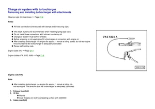
◆ VAS 5024 A pliers are recommended when installing spring-type clips.
◆ Do not install hose connections with lubricant containing oil.
◆ Charge air system must be free of leaks.
◆ Before screwing on oil supply pipe fill turbocharger at connection with engine oil.
◆ After installing turbocharger run engine for approx. 1 minute at idling speed, do not rev engine.
This ensures that the turbocharger is adequately lubricated.
◆ Renew self-locking nuts.
Engine code AHU =>Page 21-4
Engine codes AFN, AVG, AHH =>Page 21-8
Engine code AHU
Note:
◆ After installing turbocharger run engine for approx. 1 minute at idling, do
not rev engine. This ensures that the turbocharger is adequately lubricated.
1. Exhaust manifold
2. 35 Nm
◆ Renew
◆ Coat threads and bolt head seating surface with G000500
3. Intake manifold
2. 4. From charge air cooler
5. Gasket
◆ Renew
◆ Coating (beading) towards intake manifold
6. 25 Nm
7. Gasket
◆ Note installation position
8. Washer
3. 9. 25 Nm
10. Heat shield
11. To crankcase breather
12. From air cleaner
13. Hose
◆ To charge pressure control solenoid valve (N75)
=> Page 21-20
14. Banjo bolt, 15 Nm
15. Seal
◆ Renew
16. 30 Nm
17. Oil return pipe
◆ To cylinder block
18. Banjo bolt, 30 Nm
19. Gasket
◆ Renew
20. Hose
4. ◆ To charge pressure control solenoid valve (N75)
=> Page 21-20
21. 10 Nm
◆ Install with D6
22. Pressure unit
◆ For charge pressure regulating valve
◆ Checking =>Page 21-22
◆ Removing and installing
=> Page 21-23
23. Circlip
24. Turbocharger
◆ Checking => Page 21-24
◆ Checking charge pressure control
=> Page 21-33
25. Gasket
◆ Renew
26. Front exhaust pipe
5. 27. Connection, 30 Nm
◆ Renew
◆ Coat threads and bolt head seating surface with "G 052 112 A3"
◆ Before screwing on oil supply pipe fill connection with engine oil
28. Bolt
◆ Tightening torque => page 17-8, item 9
29. Oil supply pipe
◆ From oil filter bracket
=> Page 17-3, item 6
◆ Before screwing on oil supply pipe fill connection with engine oil
◆ Removing and installing =>page 17-8
Engine codes AFN, AVG, AHH
Note:
6. ◆ After installing turbocharger run engine for approx. 1 minute at idling, do
not rev engine. This ensures that the turbocharger is adequately lubricated.
1. Exhaust manifold
2. Intake manifold
3. From charge air cooler
4. Gasket
◆ Renew
◆ Coating (beading) towards intake manifold
5. 25 Nm
6. Gasket
◆ Note installation position
7. Retainer
7. ◆ For heat shield item 9
8. Washer
9. Heat shield
◆ Engage in bracket item 7
10. Pressure unit
◆ For charge pressure control
◆ Integral part of turbocharger cannot be replaced
11. Turbocharger
◆ Checking charge pressure control
=> Page 21-33
12. To crankcase breather
13. From air cleaner
14. Gasket
◆ Renew
15. 30 Nm
16. Oil return pipe
◆ To cylinder block
8. 17. Seal
◆ Renew
18. Banjo bolt, 30 Nm
19. Retainer
20. To charge air cooler
21. Gasket
◆ Renew
22. Front exhaust pipe
23. Hose
◆ To charge pressure control solenoid valve (N75)
=> Page 21-16
24. Connection, 30 Nm
◆ Renew
◆ Coat threads and bolt head seating surface with "G 052 112 A3"
9. ◆ Fill connection with engine oil before screwing on oil supply pipe.
25. Bolt
◆ Tightening torque => page 17-8, item 9
26. Oil supply pipe
◆ From oil filter bracket
=> Page 17-3, item 6
◆ Fill connection with engine oil before screwing on oil supply pipe.
◆ Removing and installing =>page 17-8
27. Retainer
28. 25 Nm
◆ Renew
◆ Coat threads and bolt head seating surface with G 000 500