The document describes a network diagram where an APoE01 device receives data and power over Ethernet from a router and provides power over Ethernet to an APoE03 device, while both the APoE01 and switch are connected to an uninterruptible power supply for backup power in case the power adapter fails.
Berhampur Call Girl Just Call 8084732287 Top Class Call Girl Service Available
APOE application diagram
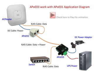
1. APoE03 work with APoE01 Application Diagram Check here to Play the animation AP/Router RJ45 Cable: Data DC Cable: Power APoE01 DC Power Adapter RJ45 Cable: Data + Power APoE03 Switch UPS Power RJ45 Cable: Data
2. APoE03 work with APoE01 Application Diagram Next AP/Router RJ45 Cable: Data DC Cable: Power Power source from Power Adapter APoE01 DC Power Adapter RJ45 Cable: Data + Power APoE03 Switch UPS Power RJ45 Cable: Data
3. APoE03 work with APoE01 Application Diagram EXIT Close Animation AP/Router RJ45 Cable: Data When No Power Source from Power Adapter Automatic take Power Source from UPS DC Cable: Power APoE01 DC Power Adapter RJ45 Cable: Data + Power APoE03 Switch UPS Power RJ45 Cable: Data