
Recommended
More Related Content
What's hot
What's hot (20)
Viewers also liked
Similar to AURORA FILTERS Portable Filtration Systems
Similar to AURORA FILTERS Portable Filtration Systems (20)
AURORA FILTERS Portable Filtration Systems
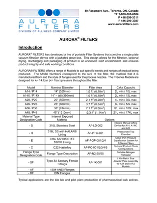
- 1. 49 Passmore Ave., Toronto, ON, Canada TF 1-888-368-8884 P 416-299-3311 F 416-299-3387 www.aurorafilters.com AURORA® FILTERS Introduction AURORA® FILTERS has developed a line of portable Filter Systems that combine a single plate vacuum filtration device with a jacketed glove box. This design allows for the filtration, optional drying, discharging and packaging of product in an enclosed, inert environment, and ensures product integrity and safe working conditions. AURORA® FILTERS offers a range of Models to suit specific needs and ranges of product being produced. The Model Numbers correspond to the size of the filter, the material that it is manufactured from and the style of flanges used for the process nozzles. The P-Series Models are designed for +/- 14.7psi (+/- 1bar) pressure throughout the filter. Model Nominal Diameter Filter Area Cake Capacity 2 A14 / P14 14” (350mm) 1.0 ft (0.10m2) 2L min / 10L max 2 A14X / P14X 14” – tall (350mm) 1.0 ft (0.10m2) 2L min / 15L max 2 A20 / P20 20” (500mm) 2.1 ft (0.20m2) 4L min / 30L max 2 2 A26 / P26 26” (660mm) 3.7 ft (0.34m ) 6L min / 52L max 2 A36 / P36 36” (914mm) 7.1 ft (0.66m2) 12L min / 100L max 2 A48 / P48 48” (1210mm) 12.3 ft (1.14m2) 21L min / 174L max Material Type Internal Exposed Designation Code Material Options Integral Manual Lifting -S 316L Stainless Steel AF-LD-002 Device for A14, A14X, and A20 316L SS with HALAR® Pressurized Top -H AF-PTC-001 Chamber Lining Glove Port Pressure 316L SS with ETFE -E AF-PGP-001/2/4 Equalization System for 1020® Lining P-Series Filters Optional Product Chute -C C22 Hastelloy AF-PC-001/2/3/4/5 Configurations Flange Type Portable Nitrogen Flange Type Description AF-N2-25/55 Preheater Designation Code I Kilo Batch Size Type 3A Sanitary Ferrule Adapter Plate Assembly - SF AF-1K-001 for A14 and A14X Fittings Models - AF 150# ANSI Flanges - DF DIN Flanges Typical applications are the kilo lab and pilot plant production of pharmaceutical bulk actives,
- 2. intermediates and fine chemicals that are sensitive to the atmosphere, or are produced in volatile solvents. General Description The filter is assembled as two chambers separated by the filtration media. Bottom Chamber – Vacuum Nutche The Bottom Chamber is the Vacuum Nutsche. The Bottom Chamber supports a fully perforated removable filter plate, which supports the customer specified filter media. The larger units have a filter support grid to give further support to the filter plate. The Bottom Chamber is fitted with a small sight glass so that the operator may monitor the rate of extraction of filtrate. The Bottom Chamber is also fitted with a Filter Cloth Retaining Ring. The A14, A14X and A20 filters are supplied with a quantity of disposable Teflon Packing material that is fitted into a groove in the mating flanges to hold the filter media in place. The larger models are supplied with a custom fitted solid ring of the same material as the filter that snaps over the filter media. There are no mechanical joints, fittings, or hardware inside the filter. Top Chamber – Glove Box The Top Chamber is the Glove Box. The size of the vessel determines the number of Glove Ports and Product Chutes. The Model A14 and A14X have one Glove Port and one Product Chute, while the A36 and A48 have two sets of Glove Ports as well as two Product Chutes. The top of the Top Chamber is fitted with a large Viewing Window to maximize the viewing access of the interior of the filter. The operator is able to control the feed and filtration process, and manipulate the filter cake using the fitted Gloves and supplied polypropylene Product Scoop. Insulated Heating/Cooling Jacket The Top Chamber is fitted with an insulated Heating/Cooling Jacket. This jacket is designed for use of heat transfer fluids such as Brine, Glycol, etc, (not for steam) operating at 50 to 75psi (bar) in a temperature range of –30C to 100C (-22F to 212F). The jacket covers the maximum slurry depth in the Top Chamber and aids in the filtration and drying sequences. Opening/Closing the Filter Opening and closing the filter is handled in a couple of manners, again dependent on the size of the filter. The A14, A14X and A20 filters require a small lifting tackle to lift the Top Chamber off of the Bottom Chamber, which is support by three legs with castors. A new optional feature the AF-LD-002 is an integral manual handling device that allows the Top and Bottom Chambers to be separated without the need for external auxiliary equipment. More information regarding this option can be obtained 2
- 3. from your AURORA® FILTERS Sales Representative or as detailed on our website. The A26, A36 and A48 filters are fitted with a self contained Hydraulic Piston System, which allows the Bottom Chamber to be raised and lowered into position by a single operator. This system is charged and ready to operate and requires very little maintenance. O-Ring Sealing System Once the chamber mating flanges are in position a series of swing bolts lock the filter chambers together. These mating flanges contain an O-Ring sealing system, which provides a liquid and vacuum tight seal between the chambers. Process Nozzles The filters are typically terminated with flanges only. The customer is responsible for supplying process valves, gas regulator system, vacuum pumping system, and any other system auxiliary equipment. AURORA FILTERS is capable of assisting with this auxiliary equipment and will price separately upon request. Preparation for Filtration Filter Media The customer is responsible for selecting and supplying the filter media to be used with the filter. A variety of combinations can be used on the same filter. The customer is required to supply a size of sample filter media to custom fit the Filter Cloth Retaining Rings for the A26, A36 and A48 models. Two Filter Cloth Retaining Rings are supplied with each filter. No filter media samples are required for the A14 and A20 models. The most commonly used media is a relatively lightweight (polyester) top cloth combined with a heavier (cotton) backing cloth, but a wide range of media can be accommodated Affixing the Filter Media In preparation for filter media installation, the Bottom Chamber must be separated from the Top Chamber. The Filter Plate Support Grid rests in the Bottom Chamber, which supports the Filter Plate so that it is near level with the upper rim of this chamber. The cloths are placed over the Filter Plate, which has 10 mm diameter perforations. The Filter Clamp Ring fits over the cloths and the Filter Plate to hold them in position. This ring is a push-fit so that there are no screws or fixing bolts within the filter. For the smaller filters, Teflon Packing is pressed onto the filter media and into a groove in the mating flanges, which holds the filter media in place. Final Equipment Installation Standard Dry Box Gloves are fitted to the Glove Ports and secured using supplied clamp rings. Scoops are supplied of polypropylene material and should be placed inside the filter prior to closing. Suitable receivers are sealed to the two Product Chutes; for example, plastic sacks supported in shipping drums. Stainless steel hose clamps are supplied to fasten the receiving bags to the Product Chute; however, the operator may decide to use a combination of tape or other methods. 3
- 4. Closing the Filter With the filter media and Product Scoop in place the filter can now be closed using the hydraulic system or lifting tackle depending on the model size and tightening the swing bolt assemblies. The assembled filter may now be rolled into position for filtration. The Filtration Process Each filter contains four flanged process connections to the Top Chamber and three flanged process connections to the Bottom Chamber. Nozzles that are not in use must be closed off with valves or blind flanges. Continuous Vent The Nozzle (A) is used to exhaust the filter to the facility’s Vent Line. It is very important to maintain this vent at all times, as the Top Chamber of the filter is not a pressure vessel and is designed specifically for atmospheric conditions. Failure to maintain atmospheric conditions will result in the gloves or product receiver bags bursting or the viewing window breaking. Inert Gas When required, an inert gas - typically nitrogen - is admitted to the filter by Nozzle (D) and briefly in Nozzle (F) for a period prior to commencing filtration. The Operator ensures a small positive pressure (0.5 to 1psi bar) of nitrogen in the filter throughout the process. Adequate pressure can be monitored by observing the small amount of pressure acting on the gloves. Please review the schematic AF-N2 for the recommended Nitrogen Gas supply system. Slurry Input Slurry is admitted via Nozzle (B) to the level of the top of the Jacket, some 20 mm (¾”) below the Product Chute. Filtrate is extracted from the base of the Bottom Chamber via Nozzle (G). (To avoid any electrical requirement in the area around the filter, a pneumatically operated diaphragm pump is typically employed.) The Operator can adjust the rate of filtrate extraction by observing the liquor level through the Bottom Chamber sight glass. Periodically the Operator should admit more slurry to the filter. During this phase of operation the filtrate extraction pump will maintain vacuum conditions in the Bottom Chamber. Heating/Cooling Jacket If the filtration process requires other than an ambient temperature, an appropriate heat transfer fluid is circulated through the Jacket via Nozzles (J) and (K). Cake Washing If the process scheme requires the filter cake to be washed, solvent may be admitted through the Wash Inlet Nozzle (C). The Operators may mix the cake using the Gloves and Scoop to assist in reslurrying the solids. 4
- 5. Final Vacuum When the batch is nearing completion, vacuum may be applied via Nozzle (E) (just below the Filter Plate) to extract the maximum amount of liquor out of the cake. As necessary throughout the process, the nitrogen flow via Nozzle (D) must be increased to maintain the small positive pressure in the Top Chamber. Pressurization of the Filter The P-Series Filters have been designed to withstand +/-14.7psi throughout the filter. In order to operate the filter under pressure conditions the Product Chute and Glove Port must be isolated from the pressure. In order to isolate the Product Chute the operator must remove the Product receiver and install the sanitary cap; gasket and clamp supplied for this connection or install a third-party isolation valve with a pressure plug adaptor. The isolation of the Glove Ports can be done two ways. The first method requires the removal of the gloves to and the installation of the supplied 8” sanitary cap, gasket and clamp prior to introducing a pressure differential to the filter. The second method is to utilize the AF-PGP-002 Option that is supplied with the P-Series filter. The 10” cap is installed over the Glove Ports prior to pressurization. The two-way valve is set to the ‘P’ (pressure) position. The Glove Port Pressure Equalization system will equal the pressure conditions from the filter on both sides of the glove to protect the glove from failure. The atmosphere within the filter is protected from the user-side of the gloves by the in-line HEPA filter in the piping. Once pressure conditions have been returned to atmospheric conditions within the filter the two- way valve is set to the ‘V’ (vent) position. In this position the operator can attach external air onto the valve and force air into the user side of the glove and vent any lingering vapours through the vent line. Using the Filter for Drying Drying, by volatilisation of solvents from the cake, can be accomplished within the filter by applying a positive flow of nitrogen (or other media) through Nozzle (F) (just below the Filter Plate). With the Vent Nozzle (A) fully open and all other nozzles closed off, the Jacket temperature should be increased to the maximum - within the filter’s range - which can be tolerated by the product. Periodically the Operator may manipulate the cake with the Product Scoop to give greater exposure of more moist areas of the cake to the drying gas. This process is meant to be a slow procedure. Increasing the flow rate of nitrogen will not necessarily accelerate the process and may in fact cause unwanted dusting and lose of product out the exhaust vent. 5
- 6. Please refer to the schematic AF-N2, for the recommended Nitrogen Gas supply system. Discharge of Filter Cake Suitable receiving containers are connected to the Product Chute. For example, a flexible plastic sack, supported in a shipping drum, may be hose clamped or taped to the chute. The Operators use the Gloves and Scoops to discharge the filter cake down the Product Chutes into the receiving containers. When completed, with the flow of nitrogen still maintaining a positive pressure, the containers may be sealed off and disconnected from the filter using a two-knot system. Product Chutes are fitted with Type 3A Sanitary Ferrule Fittings. Third party ChargePoint Valves can be easily adapted to the product chutes to add further control and safety to the handing of the finished product. For more information, contact you AURORA® FILTERS Representative. Cleaning After use, appropriate solvents may be admitted through the Wash Inlet Nozzle (C) to wash out the filter. The Wash Nozzle is fitted with a 360° Teflon CIP Spray Ball Assembly as standard supply. The filter is now opened using the hydraulic system or manual methods so that the Top and Bottom Chamber are separated. In this position a complete inspection of the filter cloth and cleaning process can be executed. With the Bottom Chamber rolled out, the Operator may sit on a small stool under the Top Chamber to complete cleaning of the larger filters or the Top Chamber can be carefully tipped to gain access in the smaller filters. The Gloves and Scoops should be cleaned and reinstalled as part of the filter, and all nozzles closed off, to await the next application. If the next application is a duplicate process of the preceding operation, the filter does not necessarily need to be cleaned between batches. 6
- 7. 7
- 8. AURORA® FILTERS SPECIAL FEATURES OPTIONS SHEET AURORA® FILTERS is working hard to accommodate the needs of our customers. Over the years, we have developed standardized products with features to meet our customer expectations; however, we have come to realize that we can’t possibly predict all of our customer’s requirements. To this end, we are offering a variety of Custom Options for our customer’s consideration. PRODUCT CHUTE OPTIONS AF-PC-001 AF-PC-002 AF-PC-003 AF-PC-004 AF-PC-005 6” Rotational 4”/6” Downward 4”/6” Downward 6” Straight Angle 6” Downward Projection Projection with Chute Projection and Vent Rotational OPTIONS HIGHLIGHT BY FEATURE CARDS 1. Top Chamber Rated For Full Vacuum – See AF-PTC-001 Feature Card 2. Glove Port Pressure Equalization System – See AF-PGP-001 Feature Card 3. Integral Handling Device for the A-Series and P-Series - 14” and 20” Filters – See AF-LD-001 Feature Card. 4. Pressure Rated Filters – See AF-PF-001 Feature Card 5. Portable Nitrogen Gas Pre-Heaters – See AF-N2-XP Feature Card OTHER OPTIONS 1. Product Chute plug 2. Spray Gun or Spray Nozzle CIP system 3. Interior Tool Hooks on A36, P36, and A48 Filters 4. Fork Lift Handling Brackets for A36, P36, And A48 Filters 5. Pressure Gauges on Upper and/or Lower Chamber 6. Customize the Height of the A-Series or P-Series - 14” and 20” Filters 7. Sampler Ports or Other Additional Nozzle Connections can be added to the design. 8. Spare Parts Kits available for all Filter Models 9. AURORA FILTERS can assist in supplying a wide range of Auxiliary Equipment including Ball Valves, Isolation Valves, Gas Regulators, Gloves, Etc. Please ask your Sales Representative for more information. 1-888-368-8884 www.aurorafilters.com August 2009
- 9. AURORA® FILTERS P-SERIES PRESSURE RATED FILTERS Model P36 Model P14X Model P20 The AURORA® FILTERS P-Series Filters are designed for 14.7psi and Full Vacuum operating conditions. These filters feature the AF-PGP-001 Glove Port Pressure Equalization System which allows the filter to be pressurized without the requirement of removing the drybox gloves and therefore maintaining containment and the protective inert environment throughout the filtration and drying sequence. The P-Series features all the standard design parameters and common safety and operating features that you are accustom to with the AURORA® FILTERS A-Series Product Line. Easy of use, Adaptability, and Quality are common to all AURORA® FILTERS products. FEATURES AND BENEFITS • Filter designed for 14.7psi to Full Vacuum conditions throughout. • Glove Box Pressure Equalization System - User protection engineered into the system with the inclusion of a HEPA Filter and purging system for each glove port. • Maintaining large viewing window for operator. • Available in all AURORA FILTERS Model sizes • ChargePoint Valve required for Product Chute – not included in scope of supply. This can be included in scope of supply or supplied directly by the user. • Can be designed to elevated pressure conditions to ASME Section VII Div 1. Please ask your Sales Representative for more information. 1-888-368-8884 www.aurorafilters.com January 2007
- 10. AURORA® FILTERS AF-PGP-001 Glove Port Pressure Equalization System For reasons of safety, as well as process purposes, many of our customers have been requesting that the entire filter be designed for pressure or full vacuum conditions. Any form of positive or negative pressure in the Upper Chamber of the AURORA® FILTER has been previously been restricted by the ability of the Viewing Window glass, the Gloves, and the Product Receiver bag to withstand a pressure condition. If the Vent Nozzle in the Upper Chamber is closed a pressure condition is immediately created within the vessel. AURORA® FILTERS has developed the AF-PGP-001 Glove Port Pressure Equalization System. THE SOLUTION The new AF-PGP-001 allows the Drybox Gloves to remain in place under pressure conditions and therefore eliminating the need of breaking the containment of the production batch. The AF-PGP-001 system captures the pressure conditions of the interior of the vessel and equalizes both sides of the dry-box gloves. A HEPA filter and Purge System protects the user from contact with hazardous chemicals or remnants of solvent vapours. A manifold purge system operates in only two positions (ON/OFF), which simplifies the process for the operator. Other Pressure Considerations The Viewing Window glass has been engineered to withstand pressure. The Product Chute must be fitted with a ChargePoint Valve system with a Passive Pressure-Retaining Plug. Included with this Option: Filter designed for 14.7psi throughout including Viewing Glass, Glove Port Pressure Retaining Caps, Pressure Equalization Piping, In- Line HEPA Filter, Internal Pressure Gauge, and Purging System Manifold Valve. Not included with this Option: Product Chute ChargePoint Valve, Process Nozzle Ball Valves. Please ask your Sales Representative for more information. 1-888-368-8884 www.aurorafilters.com
- 11. AURORA® FILTERS AF-PTC-001 Pressurized Top Chamber Design One of the repeated requests that we have had from customers is the ability to rate the Top Chamber for a pressure condition. AURORA® FILTERS has answered this request, however, we caution our customers to gain complete understanding of the process requirements for this option. Any form of positive or negative pressure in the Upper Chamber of the vessel has been restricted by the ability of the Viewing Window glass, the Gloves, and the Product Receiver bag to withstand a pressure condition. If the Vent Nozzle in the Upper Chamber is closed a pressure condition is immediately created within the vessel. THE SOLUTION The Option AF-PTC-001 deals with the engineering design of the Top Chamber and in particular the Viewing Window glass to withstand 14.7psi (1 bar) to Full Vacuum (-1 bar) of pressure. This Option assumes that the Product Chute has either been capped with the supplied Tri- Clamp Cap, Clamp and Gasket or fitted with a ChargePoint Valve system with a Passive Pressure-Retaining Plug. The AF-PTC-001 option also assumes that the Gloves have been removed from the Glove Ports and replaced with the supplied Tri-Clamp Cap, Clamp, and Gasket or the Option AF- PGP-001 has been ordered in conjunction with this Option. (Option AF-PGP-001 includes Option AF-PTC-001) The Option AF-PTC-001 does not result in the Top Chamber being able to withstand pressure without the Operator taking necessary steps to ensure that the Gloves and Product Receiver Bag have been isolated from the pressure boundary. Included with this Option: Engineered Viewing Window Glass, Engineered Top Chamber for +/- 14.7psi (+/-1 bar), and Upper Chamber Pressure Gauge. Not included with this Option: Product Chute ChargePoint Valve, AF-PGP-001 Glove Port Pressure Equalization System, and Process Nozzle Ball Valves. Please ask your Sales Representative for more information. 1-888-368-8884 www.aurorafilters.com
- 12. AURORA® FILTERS AF-1K-001 Models A14, A14X 1 Kilo Batch Adapter Plate For years our customers have been asking for an AURORA® FILTERS that can efficiently handle smaller batch sizes. The challenge has been to create a filter with all the applicable process nozzles, product discharge chute and operator glove port into a vessel with a small enough filter area size. AURORA® FILTERS has answered the call with the new AF-1K-001 – 1 Kilo Batch Adapter Plate. This option converts new and existing Model A14 and A14X AURORA FILTERS into smaller filter areas while maintaining all of the features that are inherent in the AURORA® FILTERS. The Adapter Plate Kit is customer sized to the customer required specifications to produce a ¾” (18mm) cake with an equivalent filter area as determined by the customer. The operation of the filter is exactly the same as the standard Model A14 and A14X filters. The 1 Kilo Batch Adapter Plate is made of Teflon with an accompanying filter plate in the applicable material to match the new or existing Model A14 or A14X filter. Easy to clean and adapt to your next production batch. Please ask your Sales Representative for more information. 1-888-368-8884 www.aurorafilters.com
- 13. AURORA® FILTERS AF-LD-002 Models A14, A14X, A20 Integral Handling Device The engineers at AURORA® FILTERS have been busy answering to the needs of our customers. The latest major development is the AF-LD-002 Integral Handling Device for the smaller AURORA® FILTERS Models. After manually lowering the Lower Chamber of the filter with the mechanical assist mechanism, the Lower Chamber rotates out from under the Upper Chamber. The Filter area can be either worked on in this position or lifted onto a workbench and placed onto the holding jig supplied with this option. This feature eliminates the need for any auxiliary lifting equipment within the confines of your laboratory. Please ask your Sales Representative for more information. 1-888-368-8884 www.aurorafilters.com
- 14. AURORA® FILTERS AF-N2-XP NITROGEN GAS PRE-HEATER AURORA® FILTERS is proud to announce the AF-N2-XP Series of Nitrogen Gas Pre- Heaters. This system allows operators to regulate the Pressure, Flow and Temperature of the product system inert gas in connection with all other AURORA® FILTERS Nutche Filter/Dryer products and can be adapted to other equipment in the laboratory. The small, compact, portable design is ideal for Kilo Lab and Pilot Plant facilities, has standard power requirements, and includes safety details and limits engineered into the system. SCOPE OF SUPPLY • Pressure Regulator BASIS OF DESIGN • Flow Regulator • Model AF-N2-XP1 - Suitable for use in Class I Div I • Inlet Ball Valve Groups A, B, C, D Hazardous locations • Heater and Control Panel • Model AF-N2-XP2 – Suitable for use in Class I DivII o 120VAC, 1 phase, 60Hz requirement Groups A, B, C, D Hazardous locations o Stainless Steel X-Purged enclosure with remote setpoint • Designed for Max. Input Pressure of 8.27 bar (120psi) digital temperature control on AF-N2-XP1 version. • Maximum outlet temperature tested to 80OC (175OF) o NEMA 7 RTD sensor • Maximum flow rate tested to 2.83 m3/h (100scfh) o Removable Immersion heat element – replacements • Size – 0.5m x 0.76m x 1.5m (h) (20” x 30” x 60” (h)), stocked by AURORA FILTERS 125kg (275lbs) • Insulated Outlet Hose • Options – CE Label • All stainless steel portable skid package • QA Documentation and Operating Manual Please ask your Sales Representative for more information. 1-888-368-8884 www.aurorafilters.com August 2009