1. Shenzhen KYL Communication Equipment Co., Ltd
Shenz Co.
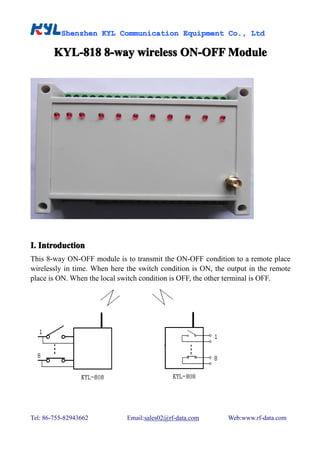
KYL-818 8-way wireless ON-OFF Module
8-way
I. Introduction
This 8-way ON-OFF module is to transmit the ON-OFF condition to a remote place
wirelessly in time. When here the switch condition is ON, the output in the remote
place is ON. When the local switch condition is OFF, the other terminal is OFF.
Tel: 86-755-82943662 Email:sales02@rf-data.com Web:www.rf-data.com
2. Shenzhen KYL Communication Equipment Co., Ltd
Shenz Co.
II. Features of KYL-818
II.
1、 8-way isolated input, high reliability and stability.
2、 8-way relay dry contact output, contact current is 220V, 5A.
3、 Collocated with a wireless data module inside whose transmitting distance
is about 2km-3km; the working frequency 433MHz (400-470MHz); RF
power: 1000mW; Receiving sensitivity: -123dBm
4、 Receiving current: 60mA; transmitting current: 350mA
5、 Power supply: DC 12V-30V
6、 Dimension: 145mm*90mm*40mm
III. Dip switch instruction
III.
Pic 1. DIP Switch
DIP8 working method
DIP8:working
ON—touch off transmitting. Once you change any of the 8 channels condition,
the module will send out this info .
OFF---fixed time transmitting. The master transmits 8 channels' condition to the
slave every 1s or 2s (not real-time transmitting).
DIP7 master and slave choosing under the fixed time transmitting mode
DIP7:master
ON—slave,OFF—host
DIP6 data collecting mode
DIP6:data
The master collects input condition or controls output condition via sending data. In
data collecting mode, the module can't send out data actively. That is to say touch off
transmitting and timing transmitting are both invalid in this mode.
DIP5 ON--no definition
DIP5:ON ON--no
Tel: 86-755-82943662 Email:sales02@rf-data.com Web:www.rf-data.com
3. Shenzhen KYL Communication Equipment Co., Ltd
Shenz Co.
DIP1-4 channel choosing
DIP1-4:channel
To avoid interference, please use different DIP switch mode and choose different
channels when you use several pairs of modules in the same place. Maximal 16
channels.
The following is a channel correspondence table for DIP switch 1-4:
Channel Channel Channel Channel
DIP No. DIP No. DIP No. DIP No.
No. No. No. No.
1 5 9 13
2 6 10 14
3 7 11 15
4 8 12 16
Notice:
* For most users "touch off transmitting mode" is OK-----DIP7-ON
* To avoid interference caused by more pairs of modules working in the same place,
please choose different channels for different systems.
* In timing mode, there should be a master and a slave.
* changing the DIP switch just takes effect after the module is re-power on.
IV. Wiring Terminal Schematic
IV.
Tel: 86-755-82943662 Email:sales02@rf-data.com Web:www.rf-data.com
4. Shenzhen KYL Communication Equipment Co., Ltd
Shenz Co.
Pic 2:Switch input wiring terminal schematic
Pic 3: Switch output wiring terminal schematic
V. Pin Definition:
Pin name Pin No. Definition Remarks
COM1 1 GND The ground of power supply
2 VCC DC:12-30V
3 - Blank
4 - Blank
st
5 OUT1 The 1 way dry contact output
6
7 OUT2 The 2nd way dry contact output
8
9 OUT3 The 3rd way dry contact output
10
11 OUT4 The 4th way dry contact output
12
13 OUT5 The 5th way dry contact output
14
15 OUT6 The 6th waydry contact output
16
17 OUT7 The 7th way dry contact output
18
19 OUT8 The 8th way dry contact output
Tel: 86-755-82943662 Email:sales02@rf-data.com Web:www.rf-data.com
5. Shenzhen KYL Communication Equipment Co., Ltd
Shenz Co.
20
COM2 1 IN1 The 1st ON-OFF condition input
2 GND
3 IN2 The 2nd ON-OFF condition input
4 GND
5 IN3 The 3rd ON-OFF condition input
6 GND
7 IN4 The 4th ON-OFF condition input
8 GND
9 IN5 The 5th ON-OFF condition input
10 GND
11 IN6 The 6th ON-OFF condition input
12 GND
13 IN7 The 7th ON-OFF condition input
14 GND
15 IN8 The 8th ON-OFF condition input
16 GND
VI. How to use KYL-818
VI.
1. Consider your specific application, set the DIP switch, connect VCC(12V-30V
DC) and switch input and output cables as per the above instruction.
2. Power supply on for the module.
3. The factory setting is touch off transmitting mode and current channel is No.1.
4. Choose different frequency points to avoid interference caused by more pairs of
modules working in the same area.
Tel: 86-755-82943662 Email:sales02@rf-data.com Web:www.rf-data.com