SlideShare a Scribd company logo
1 of 78
Download to read offline
®

WWW.CABLEJOINTS.CO.UK

THORNE & DERRICK UK
TEL 0044 191 490 1547 FAX 0044 477 5371
TEL 0044 117 977 4647 FAX 0044 977 5582
WWW.THORNEANDDERRICK.CO.UK

PANDUCT ® Wiring Duct

PANDUCT ® Wiring Duct
SA-WDCB05

Overview

(replaces SA101N64D-LP)

Overview
New Products . . . . . . . . . . . . . . . . . . . . . . . . . . . . . . . . . . . . . . . . . . . . . . . . . . . . . . . . . . . . . . . . . . . . . . . . . . . . . . . . A2
Part Number Nomenclature . . . . . . . . . . . . . . . . . . . . . . . . . . . . . . . . . . . . . . . . . . . . . . . . . . . . . . . . . . . . . . . . . . . . . . A3

Control Panel
PANDUCT ® Wiring Duct for Control Panel Applications Introduction . . . . . . . . . . . . . . . . . . . . . . . . . . . . . . . . . . . . . . B1
Control Panel Applications Roadmap . . . . . . . . . . . . . . . . . . . . . . . . . . . . . . . . . . . . . . . . . . . . . . . . . . . . . . . . . . . . B2-B3
Type G Wide Slot Wiring Duct . . . . . . . . . . . . . . . . . . . . . . . . . . . . . . . . . . . . . . . . . . . . . . . . . . . . . . . . . . . . . . . . . . B4-B5
Type F Narrow Slot Wiring Duct . . . . . . . . . . . . . . . . . . . . . . . . . . . . . . . . . . . . . . . . . . . . . . . . . . . . . . . . . . . . . . . . B6-B7
New Flush Cover Type D Round Hole Wiring Duct . . . . . . . . . . . . . . . . . . . . . . . . . . . . . . . . . . . . . . . . . . . . . . . . . . B8-B9
Type MC Metric Narrow Slot Wiring Duct . . . . . . . . . . . . . . . . . . . . . . . . . . . . . . . . . . . . . . . . . . . . . . . . . . . . . . . . B10-B11
New Type H Hinged Cover Wiring Duct . . . . . . . . . . . . . . . . . . . . . . . . . . . . . . . . . . . . . . . . . . . . . . . . . . . . . . . . . . . . B12

Control
Panel

Special Environment
PANDUCT ® Wiring Duct for Special Environments Introduction . . . . . . . . . . . . . . . . . . . . . . . . . . . . . . . . . . . . . . . . . . C1
Special Environments Selection Chart . . . . . . . . . . . . . . . . . . . . . . . . . . . . . . . . . . . . . . . . . . . . . . . . . . . . . . . . . . . C2-C3
New Type NNC Halogen Free Metric Wiring Duct . . . . . . . . . . . . . . . . . . . . . . . . . . . . . . . . . . . . . . . . . . . . . . . . . . . C4-C5
Type NE NORYL* Halogen Free Wiring Duct. . . . . . . . . . . . . . . . . . . . . . . . . . . . . . . . . . . . . . . . . . . . . . . . . . . . . . . C6-C7
New Type TMC Low Smoke/Low Toxicity Wiring Duct . . . . . . . . . . . . . . . . . . . . . . . . . . . . . . . . . . . . . . . . . . . . . . . . C8-C9

Special
Environment

Voice & Data
PANDUCT ® Wiring Duct for Communication Applications Introduction . . . . . . . . . . . . . . . . . . . . . . . . . . . . . . . . . . . . D1
Communication Applications Roadmap . . . . . . . . . . . . . . . . . . . . . . . . . . . . . . . . . . . . . . . . . . . . . . . . . . . . . . . . . . . D2-D5
New Type H Hinged Cover Wiring Duct . . . . . . . . . . . . . . . . . . . . . . . . . . . . . . . . . . . . . . . . . . . . . . . . . . . . . . . . . . . D6-D7
Type FS Solid Wall Raceway. . . . . . . . . . . . . . . . . . . . . . . . . . . . . . . . . . . . . . . . . . . . . . . . . . . . . . . . . . . . . . . . . . . D8-D9
Type G Wide Slot Wiring Duct . . . . . . . . . . . . . . . . . . . . . . . . . . . . . . . . . . . . . . . . . . . . . . . . . . . . . . . . . . . . . . . . . . . D10
1" Bend Radius Corner Strips . . . . . . . . . . . . . . . . . . . . . . . . . . . . . . . . . . . . . . . . . . . . . . . . . . . . . . . . . . . . . . . . . . . D11
Bend Radius Control Trumpet. . . . . . . . . . . . . . . . . . . . . . . . . . . . . . . . . . . . . . . . . . . . . . . . . . . . . . . . . . . . . . . . . . . . D11
TAK-TY ® Hook & Loop Cable Ties . . . . . . . . . . . . . . . . . . . . . . . . . . . . . . . . . . . . . . . . . . . . . . . . . . . . . . . . . . . . . . . . . D12
New ULTRA-CINCH ™ Hook & Loop Ties . . . . . . . . . . . . . . . . . . . . . . . . . . . . . . . . . . . . . . . . . . . . . . . . . . . . . . . . . . . . . D12
TAK-TAPE ™ Hook & Loop Strips . . . . . . . . . . . . . . . . . . . . . . . . . . . . . . . . . . . . . . . . . . . . . . . . . . . . . . . . . . . . . . . . . . . D13
TAK-TY ® Hook & Loop Cable Tie Mounts. . . . . . . . . . . . . . . . . . . . . . . . . . . . . . . . . . . . . . . . . . . . . . . . . . . . . . . . . . . . D13
Cable Management Solutions for Network Racks . . . . . . . . . . . . . . . . . . . . . . . . . . . . . . . . . . . . . . . . . . . . . . . . . . . . . D14

Voice &
Data

Tools & Accessories
PANDUCT ® Accessories and Installation Tools Introduction . . . . . . . . . . . . . . . . . . . . . . . . . . . . . . . . . . . . . . . . . . . . . E1
Accessories and Installation Tools Roadmap . . . . . . . . . . . . . . . . . . . . . . . . . . . . . . . . . . . . . . . . . . . . . . . . . . . . . . . E2-E3
New Type FL Flexible Wiring Duct . . . . . . . . . . . . . . . . . . . . . . . . . . . . . . . . . . . . . . . . . . . . . . . . . . . . . . . . . . . . . . . . . E4
Solid and Slotted Divider Wall. . . . . . . . . . . . . . . . . . . . . . . . . . . . . . . . . . . . . . . . . . . . . . . . . . . . . . . . . . . . . . . . . . . . . E5
Mounting Base . . . . . . . . . . . . . . . . . . . . . . . . . . . . . . . . . . . . . . . . . . . . . . . . . . . . . . . . . . . . . . . . . . . . . . . . . . . . . . . . E6
Wire Retainers . . . . . . . . . . . . . . . . . . . . . . . . . . . . . . . . . . . . . . . . . . . . . . . . . . . . . . . . . . . . . . . . . . . . . . . . . . . . . E6-E7
Duct Corner Strips . . . . . . . . . . . . . . . . . . . . . . . . . . . . . . . . . . . . . . . . . . . . . . . . . . . . . . . . . . . . . . . . . . . . . . . . . . . . . E8
Duct Joining Strips . . . . . . . . . . . . . . . . . . . . . . . . . . . . . . . . . . . . . . . . . . . . . . . . . . . . . . . . . . . . . . . . . . . . . . . . . . . . . E8
Mounting Brackets and Fasteners . . . . . . . . . . . . . . . . . . . . . . . . . . . . . . . . . . . . . . . . . . . . . . . . . . . . . . . . . . . . . . E9-E10
PAN-TY ® Cable Ties . . . . . . . . . . . . . . . . . . . . . . . . . . . . . . . . . . . . . . . . . . . . . . . . . . . . . . . . . . . . . . . . . . . . . . . . . . . E10
4-Way Adhesive Backed Mounts. . . . . . . . . . . . . . . . . . . . . . . . . . . . . . . . . . . . . . . . . . . . . . . . . . . . . . . . . . . . . . . . . . E11
Tie Mounts — Mechanically Applied . . . . . . . . . . . . . . . . . . . . . . . . . . . . . . . . . . . . . . . . . . . . . . . . . . . . . . . . . . . . . . . E11
Tie Anchor Mounts — Screw Applied . . . . . . . . . . . . . . . . . . . . . . . . . . . . . . . . . . . . . . . . . . . . . . . . . . . . . . . . . . . . . . E12
Low Profile Mounts — Screw Applied . . . . . . . . . . . . . . . . . . . . . . . . . . . . . . . . . . . . . . . . . . . . . . . . . . . . . . . . . . . . . . E12
Adhesive Tape . . . . . . . . . . . . . . . . . . . . . . . . . . . . . . . . . . . . . . . . . . . . . . . . . . . . . . . . . . . . . . . . . . . . . . . . . . . E12-E13
Duct Cutting Tool . . . . . . . . . . . . . . . . . . . . . . . . . . . . . . . . . . . . . . . . . . . . . . . . . . . . . . . . . . . . . . . . . . . . . . . . . . . . . E14
Duct Finger Cutting Tool . . . . . . . . . . . . . . . . . . . . . . . . . . . . . . . . . . . . . . . . . . . . . . . . . . . . . . . . . . . . . . . . . . . . . . . . E14
Duct Notching Tool . . . . . . . . . . . . . . . . . . . . . . . . . . . . . . . . . . . . . . . . . . . . . . . . . . . . . . . . . . . . . . . . . . . . . . . . . . . . E15
Nylon Rivet Installation Tool . . . . . . . . . . . . . . . . . . . . . . . . . . . . . . . . . . . . . . . . . . . . . . . . . . . . . . . . . . . . . . . . . . . . . E15

Tools &
Accessories

Technical
Info

Technical Info
Dimensions and Information. . . . . . . . . . . . . . . . . . . . . . . . . . . . . . . . . . . . . . . . . . . . . . . . . . . . . . . . . . . . . . . . . . F1-F7
Wirefill Capacity . . . . . . . . . . . . . . . . . . . . . . . . . . . . . . . . . . . . . . . . . . . . . . . . . . . . . . . . . . . . . . . . . . . . . . . . . . . F8-F11
Material Specifications. . . . . . . . . . . . . . . . . . . . . . . . . . . . . . . . . . . . . . . . . . . . . . . . . . . . . . . . . . . . . . . . . . . . . . F12-F13
Color Selection Guide. . . . . . . . . . . . . . . . . . . . . . . . . . . . . . . . . . . . . . . . . . . . . . . . . . . . . . . . . . . . . . . . . . . . . . . . . . F14
Installation Tips . . . . . . . . . . . . . . . . . . . . . . . . . . . . . . . . . . . . . . . . . . . . . . . . . . . . . . . . . . . . . . . . . . . . . . . . . . . . . . F15
Explanation of Agency Approvals and Standards . . . . . . . . . . . . . . . . . . . . . . . . . . . . . . . . . . . . . . . . . . . . . . . . . . F15-F16

Index

Index
Alphanumeric Part Number Index . . . . . . . . . . . . . . . . . . . . . . . . . . . . . . . . . . . . . . . . . . . . . . . . . . . . . . . . . . . . . G1-G5
*NORYL is a registered trademark of General Electric Company.
For service and technical support, call 800-777-3300 (outside the U.S. and Canada, see back cover).

A1
Overview

Type H — Hinged Cover
Wiring Duct

Wiring Duct
from PANDUIT ®

Designed for wire management
applications where frequent moves, adds,
changes or equipment upgrades require
repeated, easy and quick access to
duct channel.

Control
Panel

See pages B12, D6 & D7 for details.

Type FL
Special
Environment

—

Flexible Wiring Duct

Designed to route and protect wires installed in control panel
applications that require flexibility.
See page E4 for details.

Voice &
Data

Type NNC

—

Halogen Free Metric Wiring Duct

Designed for panel applications where high temperatures or halogen free
requirements exist.
See pages C4-C5 for details.

Tools &
Accessories

Type TMC — Low Smoke/Low Toxicity
Wiring Duct
Designed for wire management applications in public transportation.
Technical
Info

See pages C8-C9 for details.

Flush Cover Type D
Hole Wiring Duct

—

Round

Improved profile design provides greater
wirefill capacity.
Index

See pages B8-B9 for details.

A2
®

PANDUCT ® Wiring Duct
Overview

For over 45 years, PANDUIT ® has been the
world leader in the design and manufacture
of wiring duct in a wide selection of sizes,
styles, colors and materials. The PANDUIT ®
name has become synonymous with high
quality, innovative wiring duct products
used to route, protect and conceal wiring
in a wide variety of industrial control and
telecommunications applications. PANDUIT ®
continues to develop new wiring duct solutions
to satisfy the wire management challenges
facing our customers worldwide.

Control
Panel

Special
Environment

Wiring Duct Functional Part Number System Makes Ordering Easy
G
Type/Style
G
F
FS
H
D
NNC
NE
MC
TMC

=
=
=
=
=
=
=
=
=

.5
Nominal
Width
In. or mm

Wide Finger Flush Design
Narrow Finger Flush Design
Solid Wall Flush Design
Wide Finger Hinged Design
Round Hole Flush Design
Halogen Free Design
NORYL * Wide Finger Design
Metric Narrow Finger Design
Low Smoke Metric Design

X

.5

LG

6

-A

Nominal
Height
In. or mm

Color

Length

Voice &
Data

–A = Adhesive Backed
= Without Adhesive
(leave blank)
NM = No Mounting Holes

LG
DG
WH
BL
IB
BR
IG

=
=
=
=
=
=
=

Light Gray
Dark Gray
White
Black
Intrinsic Blue
Beige
International
Grey

Ft. or M

Tools &
Accessories

Technical
Info

Index

Note: See page F12 for UL94 requirements.
*NORYL is a registered trademark of General Electric Company.
For service and technical support, call 800-777-3300 (outside the U.S. and Canada, see back cover).

A3
Overview

Wiring Duct Overview

Notes

Control
Panel

Special
Environment

Voice &
Data

Tools &
Accessories

Technical
Info

Index

A4
Wiring Duct for Control Panel Applications

Overview

PANDUCT ® Wiring Duct is the premium wire management solution for routing and
concealing wiring in control panels. A wide variety of sizes are available to meet the wire
capacity needs and space constraints of the smallest wall mounted panels to the largest

Control
Panel

integrated systems. In addition, five innovative wiring duct styles accommodate a variety

pe G
of specification requirements, control panel designs and post-installation needs.

Some of the features and benefits found in all
PANDUCT ® Wiring Duct types include:

Special
Environment

Smooth corners and edges will not abrade wiring
or irritate hands
Integrated nonskid liner and unique cover designs
insure the duct cover will not slide once installed
or during vibration
UL Recognized as meeting the requirements of
UL Standard 1565 for Positioning Devices

Voice &
Data

CE compliant for panels that are to be exported
to Europe
Specially formulated PVC material meets the
NFPA79: 2002 flame retardancy requirements for
nonmetallic duct in industrial equipment

Tools &
Accessories

PVC material carries a UL94 flammability rating of V-0
for excellent flame retardancy

Technical
Info

Index

For service and technical support, call 800-777-3300 (outside the U.S. and Canada, see back cover).

B1
Wiring Duct for Control Panel Applications
Overview

Control
Panel

3

4

Special
Environment

2
a

1

5

Voice &
Data

a For information on the

complete line of PANDUCT
Accessories see page E1
®

1 Type H Hinged Cover Wiring Duct

Duct cover hinges open,
providing easy access to
cabling without the need to
remove the cover. Ideal for
applications with frequent
moves, adds and changes.

Tools &
Accessories

Technical
Info

PAGE B12

2 Type F Narrow Slot Wiring Duct

PAGES B6/B7

Narrow finger and slot
design for high-density
terminal blocks. Restricted
slots retain conductors.
Index

B2
Overview

Control
Panel

3 Type G Wide Slot Wiring Duct

PAGES B4/B5

Wide finger and slot design
allows both single conductors
and small cable bundles to
be easily transitioned from
the channel. Fits a wide
variety of applications.

4 Type MC Metric Wiring Duct

PAGES B10/B11

Narrow finger and slot
design for high-density
terminal blocks. Metric sizing
with DIN style mounting hole
pattern meets European
specifications.

5 Type D Flush Cover Round Hole Wiring Duct

Special
Environment

Voice &
Data

Tools &
Accessories

PAGES B8/B9

Round hole design allows the
positioning of wires at various
heights when transitioning
from the duct. Flush cover
design for increased capacity
and superior aesthetics.

Technical
Info

Index

For service and technical support, call 800-777-3300 (outside the U.S. and Canada, see back cover).

B3
Wiring Duct Control Panel

Overview

PANDUCT ® Type G — Wide Slot Wiring Duct
• Wide slot/finger design provides greater sidewall rigidity and can
be used with a wide range of wire bundle sizes
• Made of rigid PVC
• UL Recognized continuous use temperature: 50°C (122°F)
• UL94 Flammability Rating of V-0
• Provided with mounting holes
• Conforms with NFPA 79-2002 section 14.3.1 requirement for
flame retardant material

Control
Panel

Duct Size W x H

Special
Environment

Part Number

• nonmetallic, non-flame
propagating CDS
• medium impact resistance
• 331 temperature classification
• cover removal without tools

Voice &
Data

W

H
Tools &
Accessories

Reference

Page(s)

Color Availability

F14

Adhesive Tape
Technical
Info

E12, E13

Dimensions

F2

Wirefill Guide

F8

Material
Specifications

F13

Tools & Accessories D11, D12,
Section E
Installation Tips

Index

F15

In.

mm

G.5X.5LG6
G.5X1LG6
G.5X2LG6
G.5X4LG6
G.75X.75LG6
G.75X1LG6
G.75X1.5LG6
G.75X2LG6
G1X1LG6
G1X1.5LG6
G1X2LG6
G1X3LG6
G1X4LG6
G1.5X1LG6
G1.5X1.5LG6
G1.5X2LG6
G1.5X3LG6
G1.5X4LG6
G2X1LG6
G2X1.5LG6
G2X2LG6
G2X3LG6
G2X4LG6
G2X5LG6
G2.5X3LG6
G3X1LG6
G3X2LG6
G3X3LG6
G3X4LG6
G3X5LG6
G4X1.5LG6
G4X2LG6
G4X3LG6
G4X4LG6
G4X5LG6
G6X4LG6

.69 x .60
.69 x 1.06
.69 x 2.03
.69 x 4.10
.93 x .82
.93 x 1.06
.93 x 1.57
.93 x 2.03
1.26 x 1.12
1.26 x 1.62
1.26 x 2.12
1.26 x 3.12
1.26 x 4.10
1.75 x 1.12
1.75 x 1.62
1.75 x 2.12
1.75 x 3.12
1.75 x 4.10
2.25 x 1.12
2.25 x 1.62
2.25 x 2.12
2.25 x 3.12
2.25 x 4.10
2.25 x 5.10
2.75 x 3.12
3.25 x 1.12
3.25 x 2.12
3.25 x 3.12
3.25 x 4.10
3.25 x 5.10
4.25 x 1.62
4.25 x 2.12
4.25 x 3.12
4.25 x 4.10
4.25 x 5.10
6.25 x 4.15

17.5 x 15.2
17.5 x 26.9
17.5 x 51.6
17.5 x 104.1
23.6 x 20.8
23.6 x 26.9
23.6 x 39.9
23.6 x 51.6
32.0 x 28.4
32.0 x 41.1
32.0 x 53.8
32.0 x 79.2
32.0 x 104.1
44.5 x 28.4
44.5 x 41.1
44.5 x 53.8
44.5 x 79.2
44.5 x 104.1
57.2 x 28.4
57.2 x 41.1
57.2 x 53.8
57.2 x 79.2
57.2 x 104.1
57.2 x 129.5
69.9 x 79.2
82.6 x 28.4
82.6 x 53.8
82.6 x 79.2
82.6 x 104.1
82.6 x 129.5
108.0 x 41.1
108.0 x 53.8
108.0 x 79.2
108.0 x 104.1
108.0 x 129.5
158.8 x 105.4

Cover
Part
Number

Duct
Cover
Std. Ctn. Std. Ctn.
Qty.
Qty.

Length
(ft)

C.5LG6

120
120
120
60

120

6

C.75LG6

120
120
120
120

120

6

C1LG6

120
120
120
120
60

120

6

C1.5LG6

120
120
120
120
60

120

6

120

6

120

6

120

6

120

6

120

6

C2LG6

C2.5LG6

C3LG6

C4LG6

C6LG6

120
120
120
60
60
60
120
120
120
60
60
60
120
60
60
60
60
60

Part Number shown for LG (Light Gray). For other color availability see Color Selection Guide, page F14.

B4

Order number of feet required, in multiples of 6' or Standard Carton Quantity. Base and cover sold separately.
®

PANDUCT ® Wiring Duct
Overview

Non-Slip Cover

Specially Formulated
Lead-Free
Material

Rounded Edges
V-Shaped Slot
Lead-In

Flush Cover
Design
Control
Panel

Wire
Retainer
(page E6)

Restricted Slot Design

Upper Scoreline

Wide
Finger
Design

Special
Environment

Lower Scoreline

Features

Advantages

Benefits

Wide finger and slot design

Greater rigidity and larger slot width

Can be used with a wide range of wire and
bundle sizes

Smooth rounded edges

Exclusive PANDUIT ® process rounds the
edges in duct slots and at top of duct fingers

Protects hands and wiring/cabling from abrasion

Non-slip cover (co-extruded
non-slip liner inside duct covers)

Will not slide easily when installed on
duct base

Cover stays in place during shipment,
vibration and when in a vertical orientation,
eliminating rework

Flush cover design

Greater capacity than traditional duct designs

Can potentially use a smaller size wiring duct for
same number of wires

Cover sits flush with sidewall

Voice &
Data

Provides a neat and finished appearance

Double scoreline

Tools &
Accessories

Upper scoreline at base of finger allows fingers Allows quick modification for larger cabling
bundles saving installation time leading to a lower
to be broken out without tools
installed cost
Lower scoreline at base of duct allows sidewall
sections to be removed

Easier to create tee and corner junctions with full
wire carrying capacity

Lead-free

Eliminates health concerns associated with PVC
that contains lead

Provides a smooth burr-free edge when
sidewalls or fingers are broken out

Eliminates the need to deburr saving
installation time

V-shaped slot lead-in

V-shape funnels wires into slot for
easier insertion

Speeds wire installation

Restricted slot design

Once inserted wires are retained in the slot
with or without the cover being installed

Eliminates hassle and saves time during
installation and maintenance

Specially formulated material

Technical
Info

Index

For service and technical support, call 800-777-3300 (outside the U.S. and Canada, see back cover).

B5
Wiring Duct Control Panel

Overview

PANDUCT ® Type F — Narrow Slot Wiring Duct
• Narrow slot/finger design provides more slots to closer fit the
spacing of high-density terminal blocks and other hardware
• Made of rigid PVC
• UL Recognized continuous use temperature: 50°C (122°F)
• UL94 Flammability Rating of V-0
• Provided with mounting holes
• Conforms with NFPA 79-2002 section 14.3.1 requirement for
flame retardant material

Control
Panel

Special
Environment

Part Number

• nonmetallic, non-flame
propagating CDS
• medium impact resistance
• 331 temperature classification
• cover removal without tools

Voice &
Data

.20
(5.0)

.50
(12.7)
Tools &
Accessories

W

H

Technical
Info

Reference

Page(s)

Color Availability

F14

Adhesive Tape

E12, E13

Dimensions

F3

Wirefill Guide

Cover
Part
Number

F.5X.5LG6
F.5X1LG6
F.75X.75LG6
F.75X1.5LG6
F1X1LG6
F1X1.5LG6
F1X2LG6
F1X3LG6
F1X4LG6
F1.5X1LG6
F1.5X1.5LG6
F1.5X2LG6
F1.5X3LG6
F1.5X4LG6
F2X1LG6
F2X1.5LG6
F2X2LG6
F2X3LG6
F2X4LG6
F2X5LG6

.69 x .60
.69 x 1.06
.93 x .82
.93 x 1.57
1.26 x 1.12
1.26 x 1.62
1.26 x 2.12
1.26 x 3.12
1.26 x 4.10
1.75 x 1.12
1.75 x 1.62
1.75 x 2.12
1.75 x 3.12
1.75 x 4.10
2.25 x 1.12
2.25 x 1.62
2.25 x 2.12
2.25 x 3.12
2.25 x 4.10
2.25 x 5.10

17.5 x 15.2
17.5 x 26.9
23.6 x 20.8
23.6 x 39.9
32.0 x 28.4
32.0 x 41.1
32.0 x 53.8
32.0 x 79.2
32.0 x 104.1
44.5 x 28.4
44.5 x 41.1
44.5 x 53.8
44.5 x 79.2
44.5 x 104.1
57.2 x 28.4
57.2 x 41.1
57.2 x 53.8
57.2 x 79.2
57.2 x 104.1
57.2 x 129.5

F3X1LG6
F3X2LG6
F3X3LG6
F3X4LG6
F3X5LG6
F4X2LG6
F4X3LG6
F4X4LG6
F4X5LG6

3.25
3.25
3.25
3.25
3.25
4.25
4.25
4.25
4.25

82.6 x 28.4
82.6 x 53.8
82.6 x 79.2 C3LG6
82.6 x 104.1
82.6 x 129.5
108.0 x 53.8
108.0 x 79.2
C4LG6
108.0 x 104.1
108.0 x 129.5

x
x
x
x
x
x
x
x
x

1.12
2.12
3.12
4.10
5.10
2.12
3.12
4.10
5.10

120

6

C.75LG6

120
120

120

6

C1LG6

120
120
120
120
60

120

6

C1.5LG6

120
120
120
120
60

120

6

C2LG6

120
120
120
60
60
60

120

6

120
120
60
60
60

120

6

60
60
60
60

120

6

F13

B6

Installation Tips

Length
(ft)

120
120

Part Number shown for LG (Light Gray). For other color availability see Color Selection Guide, page F14.

Tools & Accessories Section E
Index

Duct
Cover
Std. Ctn. Std. Ctn.
Qty.
Qty.

C.5LG6

F8

Material
Specifications

Duct Size W x H
In.
mm

F15

Order number of feet required, in multiples of 6' or Standard Carton Quantity. Base and cover sold separately.
®

PANDUCT ® Wiring Duct
Overview

Rounded Edges

Double Restricted
Slot Design

Specially Formulated
Lead-Free Material

Non-Slip
Cover Flush Cover
Design

V-Shaped Slot
Lead-In

Control
Panel

Narrow
Finger
Design

Upper Scoreline

Lower Scoreline

Features

Advantages

Special
Environment

Benefits

Narrow finger and slot design

Provides closer spacing for use with
high-density applications

Allows further fanning of wires for neater wire
management in high-density control panels

Smooth rounded edges

Exclusive PANDUIT ® process rounds the
edges in duct slots and at top of duct fingers

Protects hands and wiring/cabling from abrasion

Non-slip cover (co-extruded
non-slip liner inside duct covers)

Will not slide easily when installed on
duct base

Cover stays in place during shipment,
vibration and when in a vertical orientation,
eliminating rework

Flush cover design

Greater capacity than traditional duct designs

Can potentially use a smaller size wiring duct for
same number of wires

Cover sits flush with sidewall

Voice &
Data

Provides a neat and finished appearance

Double scoreline

Tools &
Accessories

Upper scoreline at base of finger allows fingers Allows quick modification for larger cabling
bundles saving installation time leading to a lower
to be broken out without tools
installed cost
Lower scoreline at base of duct allows
complete side wall sections to be removed

Easier to create tee and corner junctions with full
wire carrying capacity

Lead-free

Eliminates health concerns associated with PVC
that contains lead

Provides a smooth burr-free edge when
sidewalls or fingers are broken out

Eliminates the need to deburr saving
installation time

V-shaped slot lead-in

V-shape funnels wires into slot for
easier insertion

Speeds wire installation

Double restricted slot design

Once inserted wires are retained in the slot
with or without the cover being installed

Eliminates hassle and saves time during
installation and maintenance

Specially formulated material

Second restriction retains cabling within top or Provides a neat and finished appearance
bottom portion of slot in larger wiring duct sizes

For service and technical support, call 800-777-3300 (outside the U.S. and Canada, see back cover).

Technical
Info

Index

B7
Wiring Duct Control Panel

Overview

PANDUCT ® Type D — Flush Cover Round Hole
Wiring Duct
• Round hole design has multiple rows of holes to retain and support
wire at variable heights and positions
• Made of rigid PVC
• UL Recognized continuous use temperature: 50°C (122°F)
• UL94 Flammability Rating of V-0
• Provided with mounting holes
• Conforms with NFPA 79-2002 section 14.3.1 requirement for flame
retardant material

Control
Panel

Special
Environment
Part Number

• nonmetallic, non-flame
propagating CDS
• medium impact resistance
• 331 temperature classification

Voice &
Data

• cover removal without tools

W

Tools &
Accessories

H

1.26
1.26
1.26
1.75
1.75
1.75
2.25
2.25
2.25
2.75
3.25
3.25
3.25
4.25
4.25
4.25

x
x
x
x
x
x
x
x
x
x
x
x
x
x
x
x

2.12
3.12
4.10
2.12
3.12
4.10
2.12
3.12
4.10
3.12
2.12
3.12
4.10
2.12
3.12
4.10

32.0 x 53.8
32.0 x 79.2
32.0 x 104.1
44.5 x 53.8
44.5 x 79.2
44.5 x 104.1
57.2 x 53.8
57.2 x 79.2
57.2 x 104.1
69.9 x 79.2
82.6 x 53.8
82.6 x 79.2
82.6 x 104.1
108.0 x 53.8
108.0 x 79.2
108.0 x 104.1

Cover
Part
Number

Length
(ft)

C1LG6

120
120
60

120

6

C1.5LG6

120
120
60

120

6

120

6

C2LG6
C2.5LG6

120
60
60
120

120

6

C3LG6

120
60
60

120

6

C4LG6

60
60
60

120

6

Page(s)

Color Availability

F14

Adhesive Tape

E12

Dimensions

F2

Wirefill Guide

F8

Material
Specifications

F13

Tools & Accessories Section E
Installation Tips

F15

Index

B8

Duct
Cover
Std. Ctn. Std. Ctn.
Qty.
Qty.

Part Number shown for LG (Light Gray). For other color availability see Color Selection Guide, page F14.

Reference

Technical
Info

D1X2LG6
D1X3LG6
D1X4LG6
D1.5X2LG6
D1.5X3LG6
D1.5X4LG6
D2X2LG6
D2X3LG6
D2X4LG6
D2.5X3LG6
D3X2LG6
D3X3LG6
D3X4LG6
D4X2LG6
D4X3LG6
D4X4LG6

Duct Size W x H
In.
mm

Order number of feet required, in multiples of 6' or Standard Carton Quantity. Base and cover sold separately.
®

PANDUCT ® Wiring Duct
Overview

Non-Slip Cover
Rounded Edges

Flush Cover
Design

Specially Formulated
Lead-Free
Material

Control
Panel

Round
Hole
Design

Special
Environment

Base Scoreline

Features

Advantages

Benefits

Round hole design

Retains and supports wires at variable heights Superior aesthetics and wire management
and positions with or without the cover installed

Flush cover design

Greater capacity than traditional duct designs

Can potentially use a smaller size wiring duct for
same number of wires

Cover sits flush with sidewall

Provides a neat and finished appearance

Non-slip cover (co-extruded
non-slip liner inside duct covers)

Will not slide easily when installed on
duct base

Cover stays in place during shipment,
vibration and when in a vertical orientation,
eliminating rework

Smooth rounded edges

Exclusive PANDUIT ® process rounds the
edges of punched holes

Protects hands and wiring/cabling from abrasion

Specially formulated material

Lead-free

Eliminates health concerns associated with PVC
that contains lead

Provides a smooth burr-free edge when
sidewalls are broken out

Eliminates the need to deburr saving
installation time

Scoreline at base of duct allows sidewall
sections to be removed

Easier to create tee and corner junctions with full
wire carrying capacity

Base scoreline

Voice &
Data

Tools &
Accessories

Technical
Info

Index

For service and technical support, call 800-777-3300 (outside the U.S. and Canada, see back cover).

B9
Wiring Duct Control Panel

Overview

PANDUCT ® Type MC — Metric Narrow Slot Wiring Duct
• CE compliant and metric sizing for control panels intended for
European applications
• Made of rigid PVC
• UL Recognized continuous use temperature: 50°C (122°F)
• UL94 Flammability Rating of V-0
• Provided with DIN 43 659 mounting holes
• Duct and cover packaged together in 2 meter lengths
• Conforms with NFPA 79-2002 section 14.3.1 requirement for
flame retardant material

Control
Panel

Special
Environment

Part Number

• nonmetallic, non-flame
propagating CDS
• medium impact resistance
• 331 temperature classification
• cover removal without tools

Voice &
Data

5.0
(.20)

12.5
(.49)
Tools &
Accessories

W

H

MC25X25IG2
MC25X37IG2
MC25X50IG2
MC25X62IG2
MC25X75IG2
MC37X37IG2
MC37X50IG2
MC37X62IG2
MC37X75IG2
MC50X50IG2
MC50X75IG2
MC50X100IG2
MC62X37IG2
MC62X62IG2
MC75X50IG2
MC75X62IG2
MC75X75IG2
MC75X100IG2
MC100X50IG2
MC100X62IG2
MC100X75IG2
MC100X100IG2

Duct Size W x H
mm
In.
24.6
24.6
24.6
24.6
24.6
37.1
37.1
37.1
37.1
49.5
49.5
49.5
62.0
62.0
74.7
74.7
74.7
74.7
99.6
99.6
99.6
99.6

x
x
x
x
x
x
x
x
x
x
x
x
x
x
x
x
x
x
x
x
x
x

23.6
35.8
47.8
59.7
72.4
35.8
47.8
59.7
72.4
47.8
72.4
97.8
35.8
59.7
48.0
59.7
72.4
97.8
48.0
59.7
72.4
97.8

Available in IG (International Gray) only.

Technical
Info

F14

Adhesive Tape

E12

Dimensions

F4

Wirefill Guide

F9

Material
Specifications

B10

Page(s)

Color Availability

Index

Reference

F13

Tools & Accessories Section E
Installation Tips

F15

Order number of pieces required, in multiples of Standard Package Quantity.

.97 x .93
.97 x 1.41
.97 x 1.88
.97 x 2.35
.97 x 2.85
1.46 x 1.41
1.46 x 1.88
1.46 x 2.35
1.46 x 2.85
1.95 x 1.89
1.95 x 2.85
1.95 x 3.85
2.44 x 1.41
2.44 x 2.35
2.94 x 1.89
2.94 x 2.35
2.94 x 2.85
2.94 x 3.85
3.92 x 1.89
3.92 x 2.35
3.92 x 2.85
3.92 x 3.85

Replacement
Duct
Cover
Cover Part
Std. Ctn. Std. Ctn.
Number
Qty.
Qty.

Length
(M)

C25IG2

20
20
20
20
20

20

2

C37IG2

20
20
20
20

20

2

C50IG2

20
10
10

20

2

C62IG2

20
20

20

2

C75IG2

20
20
10
10

20

2

C100IG2

10
10
10
10

20

2
®

PANDUCT ® Wiring Duct
Overview

Non-Slip Cover

Double Restricted
Slot Design
V-Shaped Slot Lead-In

Control
Panel

Specially Formulated
Lead-Free
Material
Rounded
Edges

Narrow
Finger
Design

Metric
Finger Width
and
Progression

Special
Environment

Lower Scoreline
Upper Scoreline

Features
Metric size and finger progression

Advantages

DIN Mounting Hole Pattern

Benefits

Slot width and pitch may match more closely to Provides a metric sized wiring duct solution for
components with metric dimensions
applications that specify metric dimensioning,
such as when exporting equipment to
European countries

Narrow finger and slot design

Provides closer spacing for use with
high-density applications

Allows further fanning of wires for neater wire
management in high-density control panels

DIN 43 659 mounting hole pattern

Provides the required mounting hole pattern
for use in cabinets which are designed to
these standards

Meets European standards for use in
cabinet applications

Smooth rounded edges

Exclusive PANDUIT ® process rounds the
edges in duct slots and at top of duct fingers

Protects hands and wiring/cabling from abrasion

Double scoreline

Upper scoreline at base of finger allows fingers Allows quick modification for larger cabling
bundles saving installation time leading to a lower
to be broken out without tools
installed cost

Voice &
Data

Lower scoreline at base of duct allows sidewall
sections to be removed

Easier to create tee and corner junctions with full
wire carrying capacity

Lead-free

Eliminates health concerns associated with PVC
that contains lead

Provides a smooth burr-free edge when
sidewalls or fingers are broken out

Eliminates the need to deburr saving
installation time

Non-slip cover (co-extruded
non-slip liner inside duct covers)

Will not slide easily when installed on
duct base

Cover stays in place during shipment,
vibration and when in a vertical orientation,
eliminating rework

Flush cover design

Greater capacity than traditional duct designs

Can potentially use a smaller size wiring duct for
same number of wires

Cover sits flush with sidewall

Provides a neat and finished appearance

Once inserted wires are retained in the slot
with or without the cover being installed

Eliminates hassle and saves time during
installation and maintenance

Tools &
Accessories

Specially formulated material

Double restricted slot design

Technical
Info

Index

Second restriction retains cabling within top or Provides a neat and finished appearance
bottom portion of slot in larger wiring duct sizes

For service and technical support, call 800-777-3300 (outside the U.S. and Canada, see back cover).

B11
Wiring Duct Control Panel

Overview

PANDUCT ® Type H — Hinged Cover Wiring Duct
•
•
•
•

Made of rigid PVC
UL Recognized continuous use temperature: 50°C (122°F)
UL94 Flammability Rating of V-0
Provided with mounting holes

Control
Panel

Duct Size WxH

Special
Environment

Voice &
Data

Part Number
H1.5X2LG6
H1.5X3LG6
H2X2LG6
H2X3LG6
H2X4LG6
H3X3LG6
H3X4LG6
H4X4LG6

H

In.

mm

1.75 x 1.98
1.75 x 3.06
2.17 x 1.98
2.17 x 3.06
2.17 X 4.10
3.25 x 3.06
3.25 x 4.10
4.25 x 4.10

44.5 x 50.3
44.5 x 77.7
55.1 x 50.3
55.1 x 77.7
55.1 X 104.1
82.6 x 77.7
82.6 x 104.1
108.0 x 104.1

Cover
Part
Number
HC1.5LG6
HC1.5LG6
HC2LG6
HC2LG6
HC2LG6
HC3LG6
HC3LG6
HC4LG6

Available in BL (Black), LG (Light Gray) and WH (White).

W

Reference
Color Availability

F14

Adhesive Tape

E12

Dimensions

F7

Wirefill Guide

F9

Material
Specifications

Tools &
Accessories

Page(s)

F13

Tools & Accessories D11, D12,
Section E
Installation Tips

F15

Technical
Info

Index

B12

Order number of feet required, in multiples of 6' or Standard Carton Quantity. Base and cover sold separately.

Duct
Cover
Std. Ctn. Std. Ctn.
Qty.
Qty.
120
120
120
60
60
60
60
60

120
120
120
120
120
120
120
60

Length
(ft)
6
6
6
6
6
6
6
6
Wiring Duct for Special Environments

Overview

PANDUIT ® offers a selection of special materials in PANDUCT ® Wiring Duct for
routing and concealing wiring in special use environments. Special use environments
include applications such as transportation, oil and gas platforms, nuclear power plants

Control
Panel

Environment/Material Specifications

and semiconductor and electronics manufacturing.

Some of the features and benefits found in PANDUCT ®
Wiring Duct types for special environments include:

Special
Environment

Specialty materials will not release toxic or
corrosive gases that could endanger public safety or
damage sensitive electronics, and exhibits excellent
flame retardance
Flush cover design to maximize capacity over the
channel footprint and provide a neater appearance

Voice &
Data

Integrated non-skid liner insures the duct cover will
not slide once installed or during vibration
Smooth corners and edges will not abrade cabling or
irritate hands
UL Recognized as meeting the requirements of
UL Standard 1565 for Positioning Devices

Tools &
Accessories

CE compliant for panels that are to be exported
to Europe

Technical
Info

Index

For service and technical support, call 800-777-3300 (outside the U.S. and Canada, see back cover).

C1
Wiring Duct for Special Environments
Overview

Control
Panel

Type NNC Halogen Free Metric Wiring Duct

Halogen free material is nontoxic, lead-free,
environmentally safe and will not release toxic
or corrosive gases that could endanger public
safety or damage sensitive electronic equipment

Special
Environment

UL94V-0

Data &
Voice

Type NE NORYL* Halogen Free Wiring Duct
Halogen free material is nontoxic, lead-free,
environmentally safe and will not release toxic
or corrosive gases that could endanger public
safety or damage sensitive electronic equipment
UL94V-1

Tools &
Accessories

Type TMC Low Smoke/Low Toxicity Wiring Duct

Low smoke/Low toxicity material emits a low
level of toxic fumes and low smoke emissions
when burned

Technical
Info

Meets Federal Rail Administration Guidelines and
NFPA 130 requirements for all transit vehicles
UL94V-0

Index

The material is
self-extinguishing and
has excellent flame
retardancy UL94V-0.

*NORYL is a registered trademark of General Electric Company.

C2

The material does
not release dense
smoke when burned
per ASTM E662 test
method.

The material does
not emit a high
volume of toxic gases
when burned per
Boeing and Airbus
test methods.
Overview

Control
Panel

Environment/Material Specifications

Typical Applications

PAGES

C4/C5

Semiconductor Manufacturing
Ship Building
Nuclear Power Plants
Oil Platforms

Environment/Material Specifications

Typical Applications

Special
Environment

PAGES

C6/C7

Data &
Voice

Semiconductor Manufacturing
Ship Building
Nuclear Power Plants
Oil Platforms

Tools &
Accessories

Environment/Material Specifications

Typical Applications

PAGES

C8/C9

Passenger Rail Cars
Other Transportation Vehicles
Technical
Info

The material contains
no fluorine, bromide
or chlorine and will not
emit any corrosive or
toxic gases when
burned per IEC 60754-2
test method.

Material is rated
for a continuous use
temperature above
75˚ C (167˚ F).
Index

For service and technical support, call 800-777-3300 (outside the U.S. and Canada, see back cover).

C3
Wiring Duct Special Environments

Overview

PANDUCT ® Type NNC — Halogen Free Metric Wiring Duct
• Made of halogen free material and verified with IEC 60754-2
test method (test on gases evolved during combustion of
electric cables)
• UL Recognized continuous use temperature: 95°C (203°F)
• UL94 Flammability Rating of V-0
• Conforms with NFPA 79-2002 section 14.3.1 requirement for
flame retardant material
• Provided with DIN 43 659 mounting holes
• Metric sizing and finger progression
• Duct and cover packaged together in 2 meter lengths

Control
Panel

Special
Environment

Duct Size WxH
mm
In.

Part Number
• nonmetallic, non-flame
propagating CDS
• medium impact resistance
• 211 temperature classification
• cover removal without tools

Data &
Voice

W

H

NNC25X25LG2
NNC25X37LG2
NNC25X50LG2
NNC25X75LG2
NNC37X37LG2
NNC37X50LG2
NNC37X75LG2
NNC50X50LG2
NNC50X75LG2
NNC50X100LG2
NNC75X75LG2
NNC100X50LG2
NNC100X75LG2
NNC100X100LG2

24.6
24.6
24.6
24.6
37.1
37.1
37.1
49.5
49.5
49.5
74.7
99.6
99.6
99.6

Technical
Info

Reference

Page(s)

Color Availability

F14

Adhesive Tape

E12

Dimensions

F5

Wirefill Guide

F9

Material
Specifications

F13

Tools and
Accessories
Installation Tips

C4

23.6
35.8
47.8
72.4
35.8
47.8
72.4
47.8
72.4
97.8
72.4
47.8
72.4
97.8

.97 x .93
.97 x 1.41
.97 x 1.88
.97 x 2.85
1.46 x 1.41
1.46 x 1.88
1.46 x 2.85
1.95 x 1.88
1.95 x 2.85
1.95 x 3.85
2.94 x 2.85
3.92 x 1.88
3.92 x 2.85
3.92 x 3.85

Duct
Cover
Std. Ctn. Std. Ctn.
Qty.
Qty.

Length
(M)

NC25LG2

20
20
20
20

20
20
20
20

2

NC37LG2

20
20
20

20
20
20

2

20
10
10
10

20
20
20
20

10
10
10

20
20
20

NC50LG2
NC75LG2
NC100LG2

2
2
2

Available in LG (Light Gray) and WH (White).
Do not allow cutting, tapping or cleaning fluids that contain hydrocarbons to come in contact with Type NNC
Wiring Duct as it will cause stress cracking. See page F15 for a list of chemicals to avoid.

Tools &
Accessories

Index

x
x
x
x
x
x
x
x
x
x
x
x
x
x

Replacement
Cover Part
Number

E9, E10,
E13, E14
F15

Order number of meters required, in multiples of Standard Carton Quantity.
®

PANDUCT ® Wiring Duct
Overview

Rounded Edges
V-Shaped Slot Lead-In

Halogen Free
Non-Slip
Cover Liner

Restricted Slots

Control
Panel

Specially Formulated
Halogen Free
Material
Metric Finger
Width and
Progression

Special
Environment

Upper Scoreline
Features

Lower Scoreline

Advantages

Benefits

Material is nontoxic, lead-free, environmentally
safe and will not release toxic or corrosive
gases that could endanger public safety or
damage sensitive electronics

Ideal for application where public safety during a
fire is a concern

Greater resistance to heat than PVC

Suitable for panel applications where high
temperatures exist

UL94V-0 material flame rating

The V-0 flammability rating exceeds the rating
of most other halogen free duct materials

Material is self-extinguishing and exhibits the
highest flame retardance meeting more electrical
panel applications

Halogen free non-slip cover liner

Cover will not slide easily when installed on
duct base

Cover stays in place during shipment,
vibration and when in a vertical orientation,
eliminating rework

Co-extruded liner made from halogen
free material

Liner will not emit corrosive or toxic gases

DIN 43 659 mounting hole pattern

Provides the required mounting hole pattern
for use in cabinets which are designed to
these standards

Meets European standards for use in
cabinet applications

Smooth rounded edges

Exclusive PANDUIT ® process rounds the
edges in duct slots and at top of duct fingers

Protects hands and wiring/cabling from abrasion

Double scoreline

Upper scoreline at base of finger allows fingers Allows quick modification for larger cabling
bundles saving installation time leading to a lower
to be broken out without tools
installed cost

Halogen free modified
PPO material

Material is recyclable and suitable for applications
requiring eco-friendly materials

Lower scoreline at base of duct allows sidewall
sections to be removed

Easier to create tee and corner junctions with full
wire carrying capacity

V-shaped slot lead-in

V-shape funnels wires into slot for
easier insertion
Once inserted wires are retained in the slot
with or without the cover being installed

Provides a neat and finished appearance

Duct and cover packaged together

Fewer part numbers to stock and manage

Reduced inventory cost

Metric size and finger progression

Technical
Info

Eliminates hassle and saves time during
installation and maintenance

Second restriction retains cabling within top
or bottom portion of slot in larger wiring
duct sizes

Tools &
Accessories

Speeds wire installation

Double restricted slot design

Voice &
Data

Slot width and pitch may match more closely to Provides a metric sized wiring duct solution for
components with metric dimensions
applications that specify metric dimensioning,
such as when exporting equipment to
European countries
For service and technical support, call 800-777-3300 (outside the U.S. and Canada, see back cover).

Index

C5
Wiring Duct Special Environments

Overview

PANDUCT ® Type NE — NORYL* Halogen Free Wiring Duct
• Made of halogen free NORYL* material
• UL94 Flammability Rating of V-1
• Provided with mounting holes
Control
Panel

Special
Environment

Part Number

Duct Size W x H
In.
mm

• medium impact resistance
• 211 temperature classification
• cover removal without tools

Data &
Voice

Tools &
Accessories

W

H

Page(s)

Color Availability

F14

F13

Tools and
Accessories

Section E

Installation Tips

F15

*NORYL is a registered trademark of General Electric Company.

C6

x
x
x
x

2.06
3.06
4.06
5.06

Duct
Cover
Std. Ctn. Std. Ctn.
Qty.
Qty.

Length
(ft)

NC.5WH6

120
120

120

6

NC1WH6

120
120
120
120
60

120

6

NC1.5WH6

120
120
120
60

120

6

120

6

NC2WH6

NC2.5WH6

120
120
60
60
120

120

6

NC3WH6

120
120
60
60
60

120

6

105.2 x 52.3
105.2 x 77.7
NC4WH6
105.2 x 103.1
105.2 x 128.5

60
60
60
60

120

6

Available in WH (White) only.
Do not allow cutting, tapping or cleaning fluids that contain hydrocarbons to come in contact with Type NE
Wiring Duct as it will cause stress cracking. See page F15 for a list of chemicals to avoid.

F10

Material
Specifications

4.14
4.14
4.14
4.14

F6

Wirefill Guide

16.0 x 14.2
16.0 x 26.9
29.0 x 26.9
29.0 x 41.1
29.0 x 52.3
29.0 x 77.7
29.0 x 103.1
41.7 x 41.1
41.7 x 52.3
41.7 x 77.7
41.7 x 103.1
54.4 x 26.9
54.4 x 52.3
54.4 x 77.7
54.4 x 103.1
67.1 x 77.7
79.8 x 26.9
79.8 x 52.3
79.8 x 77.7
79.8 x 103.1
79.8 x 128.5

E12, E13

Dimensions

Index

Reference

Adhesive Tape

Technical
Info

.63 x .56
.63 x 1.06
1.14 x 1.06
1.14 x 1.62
1.14 x 2.06
1.14 x 3.06
1.14 x 4.06
1.64 x 1.62
1.64 x 2.06
1.64 x 3.06
1.64 x 4.06
2.14 x 1.06
2.14 x 2.06
2.14 x 3.06
2.14 x 4.06
2.64 x 3.06
3.14 x 1.06
3.14 x 2.06
3.14 x 3.06
3.14 x 4.06
3.14 x 5.06

NE4X2WH6
NE4X3WH6
NE4X4WH6
NE4X5WH6

• nonmetallic, non-flame
propagating CDS

NE.5X.5WH6
NE.5X1WH6
NE1X1WH6
NE1X1.5WH6
NE1X2WH6
NE1X3WH6
NE1X4WH6
NE1.5X1.5WH6
NE1.5X2WH6
NE1.5X3WH6
NE1.5X4WH6
NE2X1WH6
NE2X2WH6
NE2X3WH6
NE2X4WH6
NE2.5X3WH6
NE3X1WH6
NE3X2WH6
NE3X3WH6
NE3X4WH6
NE3X5WH6

Cover
Part
Number

Order number of pieces required, in multiples of Standard Package Quantity.
®

PANDUCT ® Wiring Duct
Overview

V-Shaped Slot Lead-In

Non-Slip
Cover

Halogen Free
Material

Restricted Slot
Design

Control
Panel

Rounded Edges
Special
Environment

Base Scoreline

Features

Advantages

Benefits

Material is nontoxic, lead-free, environmentally
safe and will not release toxic or corrosive
gases that could endanger public safety or
damage sensitive electronics

Ideal for applications where public safety during a
fire is a concern

Greater resistance to heat than PVC

Suitable for panel applications where high
temperatures exist

Smooth rounded edges

Exclusive PANDUIT ® process rounds the
edges in duct slots and at top of duct fingers

Protects hands and wiring/cabling from abrasion

Non-slip cover (co-extruded
non-slip liner inside duct covers)

Will not slide easily when installed on
duct base

Cover stays in place during shipment,
vibration and when in a vertical orientation,
eliminating rework

Halogen free NORYL* material

Material is recyclable and suitable for applications
requiring eco-friendly materials

Base scoreline

Scoreline at base of duct allows sidewall
sections to be removed
V-shape funnels wires into slot for
easier insertion

Speeds wire installation

Restricted slot design

Once inserted wires are retained in the slot
with or without the cover being installed

Tools &
Accessories

Easier to create tee and corner junctions with full
wire carrying capacity

V-shaped slot lead-in

Voice &
Data

Eliminates hassle and saves time during
installation and maintenance
Technical
Info

Index

*NORYL is a registered trademark of General Electric Company.
For service and technical support, call 800-777-3300 (outside the U.S. and Canada, see back cover).

C7
Overview

Wiring Duct Special Environments
PANDUCT ® Type TMC — Low Smoke/Low Toxicity Wiring Duct
•
•
•
•

Made of low smoke, low toxicity and low flammability material
UL Recognized continuous use temperature: 80°C (176°F)
UL94 Flammability Rating of V-0
Conforms with NFPA 79-2002 section 14.3.1 requirement for
flame retardant material
• Provided with DIN 43 659 mounting holes
• Metric sizing and finger progression
• Duct and cover packaged together in 2 meter lengths

Control
Panel

Duct Size W x H

Special
Environment

Part Number

• nonmetallic, non-flame
propagating CDS
• medium impact resistance
• 331 temperature classification
• cover removal without tools

24.6
37.1
49.5
74.7
74.7
99.6
99.6

x
x
x
x
x
x
x

35.8
35.8
48.0
48.0
73.2
48.0
73.2

In.
.97 x 1.41
1.46 x 1.41
1.95 x 1.89
2.94 x 1.89
2.94 x 2.88
3.92 x 1.89
3.92 x 2.88

Duct
Cover
Std. Ctn. Std. Ctn.
Qty.
Qty.

Length
(M)

TC25BR2
TC37BR2
TC50BR2

20
20
20

20
20
20

2
2
2

TC75BR2

20
10

20

2

TC100BR2

10
10

20

2

Available in BR (Natural Beige) only.

Data &
Voice

Reference

Page(s)

Color Availability

F14

Adhesive Tape

E12

Dimensions

F4

Wirefill Guide

F9

Material
Specifications

F13

Tools and
Accessories

Section E

Installation Tips

Tools &
Accessories

TMC25X37BR2
TMC37X37BR2
TMC50X50BR2
TMC75X50BR2
TMC75X75BR2
TMC100X50BR2
TMC100X75BR2

mm

Replacement
Cover Part
Number

F15

W

H

PANDUCT ® Type TMC — Low Smoke / Low Toxicity Solid Divider Wall
Technical
Info

• TMC Divider Wall can be mounted inside TMC Wiring Duct to create
multiple channels
• Low smoke, low toxicity and low flammability material
• Simply install the divider wall base when mounting the duct and snap the divider wall
onto mounting base (part No. DB-C)

Part Number
Index

For Nominal Duct Height (mm)

Std.
Pkg.
Qty.

TMC50DW2
TMC75DW2

50
75

2
2

Std.
Ctn.
Qty.

Length
(M)

20
20

2
2

NOTE: Must be used with Mounting Base (DB-C) which is sold separately. Install mounting bases to the duct
channel, locate within 2" of each divider wall end and at least every 12" along the length.

C8

Order number of meters required, in multiples of Standard Carton Quantity.
®

PANDUCT ® Wiring Duct
Overview

Rounded Edges
Double Restricted Slot

Control
Panel

V-Shaped Slot
Lead-In

Low Smoke
Low Toxicity
Material

Metric
Finger Width
and
Progression

Special
Environment

Lower Scoreline
Upper Scoreline

Features

Advantages

Benefits

Material emits a low level of toxic fumes when
burned per Boeing BSS 7239 and Airbus ATS
1000.01 test methods

Meets the low toxicity requirements of many Mass
Transit OEM applications
Passenger safety in the case of a fire

Zero flame spread per ASTM E 162
test method

Meets the Federal Rail Administration Guidelines
and National Fire Protection Agency NFPA 130
standards for Mass Transit OEM applications
Material is self-extinguishing and exhibits excellent
flame retardance

Excellent fire resistance

Passenger safety in the case of a fire

Material is 40% lighter than aluminum

Contributes to a reduction in vehicle weight
lending to energy savings

Easier to handle than metal channel and can
be field cut and installed

Reduces installer fatigue and simplifies installation
steps leading to a lower installed cost

Cuts leave smooth, burr-free edges

Eliminates need to deburr cut edges simplifying
installation and reducing concern of wire abrasion

Nonconductive

Lightweight nonmetallic material

Passenger safety in the case of a fire

Material maintains a UL94V-0
flammability rating

Low flammability material

Meets the Federal Rail Administration Guidelines
and National Fire Protection Agency NFPA 130
standards for Mass Transit OEM applications

Emits low levels of toxic fumes when burned

Low toxicity material

Low smoke emissions material per ASTM E
662 test method
Low smoke emissions result in improved
visibility during a fire

Low smoke emission material

Grounding and bonding of the channel is not
required simplifying installation

Non-slip cover (co-extruded nonslip liner inside duct covers)

Will not slide easily when installed on
duct base
Exclusive PANDUIT ® process rounds the
edges in duct slots and at top of duct fingers

Upper scoreline at base of finger allows fingers Allows quick modification for larger cabling
bundles saving installation time leading to a lower
to be broken out without tools
installed cost

Technical
Info

Protects hands and wiring/cabling from abrasion

Double scoreline

Tools &
Accessories

Cover stays in place during shipment,
vibration and when in a vertical orientation,
eliminating rework

Smooth rounded edges

Voice &
Data

Lower scoreline at base of duct allows sidewall
sections to be removed

Index

Easier to create tee and corner junctions with full
wire carrying capacity

For service and technical support, call 800-777-3300 (outside the U.S. and Canada, see back cover).

C9
Overview

Wiring Duct Special Environments

Notes

Control
Panel

Special
Environment

Data &
Voice

Tools &
Accessories

Technical
Info

Index

C10
Wiring Duct for Voice & Data Applications

Overview

PANDUIT ® offers PANDUCT ® Wiring Duct styles specially suited for routing and concealing
cabling in communications applications. Applications include wire management for backboard
mounted voice, data and video applications, cord management near workstations, use

Control
Panel

inside communications cabinets and other general purpose applications.

Some of the features and benefits found in
PANDUCT ® Wiring Duct types for communications
applications include:

Special
Environment

Black color to compliment the look of
telecommunications racks and hardware

PANDUIT ® exclusive wide slot/wide finger
progression and hinging cover provides easy
access ideal for frequent moves, adds and changes

Voice &
Data

Solid wall raceway completely conceals cabling
in applications where frequent breakouts are
not required
Bend radius control accessories for cabling as
required in NFPA 79-2002 section 14.1.4.9 and
TIA/EIA 568-B and 569-A

Tools &
Accessories

Smooth corners and edges that will not abrade
cabling or irritate hands
UL94 flammability rating of V-0 for excellent
flame retardancy

Technical
Info

Index

For service and technical support, call 800-777-3300 (outside the U.S. and Canada, see back cover).

D1
Wiring Duct for Backboard Applications
Overview

Control
Panel

1

Special
Environment

Voice &
Data

2

Tools &
Accessories
3

Technical
Info

4

Index

For Cable Management Solutions for Network Racks see page D14.
D2
Overview

1 Type H Hinged Cover Wiring Duct

PAGE D6/D7

Features wide slot/wide
finger progression for
communications cabling.
Provides easy access to
cabling for moves, adds
and changes.

2 Bend Radius Control Corner Strips

PAGE D11

Snap to duct walls at tee
intersections and right
angles to provide cable
protection around corners.

3 Bend Radius Control Trumpet

™

Special
Environment

Voice &
Data

PAGE D11

Provides a smooth
transition from hardware
to duct channel.

4 TAK-TAPE Hook & Loop Strips

Control
Panel

PAGE D13

Secure cable bundles
entering or exiting the wiring
duct. Tape roll allows any
size cable bundle to be
easily secured.

For service and technical support, call 800-777-3300 (outside the U.S. and Canada, see back cover).

Tools &
Accessories

Technical
Info

Index

D3
Cord Management at the Workstation
Overview

Control
Panel

Special
Environment

2

Voice &
Data
1

3

Tools &
Accessories

4

Technical
Info

Index
®

For information on the complete line of PANDUCT Wiring Duct see page B1

D4
Overview

1 Type H Hinged Cover Wiring Duct

PAGE D6/D7

Contain cable slack at the
workstation. Hinged cover
provides easy access to
cabling for moves, adds
and changes.

2 Wire Retainers

PAGE D12

Contain cabling when
duct cover is opened.
Wire retainers snap easily
between duct fingers.

3 ULTRA-CINCH Hook & Loop Ties
™

TAK-TY Hook & Loop Cable Ties
®

®

Special
Environment

Voice &
Data

PAGE D12

Very easy to release and
reuse, making them ideal for
applications where changes
are anticipated or continuous
access is required.

4 TAK-TY Hook & Loop Cable Tie Mounts

Control
Panel

PAGE D13

Route and secure sensitive
communication cabling
without damaging the cable
bundles. Optional adhesive
backed mounts can be easily
mounted within the wiring
duct base.

For service and technical support, call 800-777-3300 (outside the U.S. and Canada, see back cover).

Tools &
Accessories

Technical
Info

Index

D5
Wiring Duct Voice & Data

Overview

PANDUCT ® Type H — Hinged Cover Wiring Duct
•
•
•
•

Made of rigid PVC
UL Recognized continuous use temperature: 50°C (122°F)
UL94 Flammability Rating of V-0
Provided with mounting holes

Control
Panel

Duct Size WxH

Special
Environment

Part Number
H1.5X2BL6
H1.5X3BL6
H2X2BL6
H2X3BL6
H2X4BL6
H3X3BL6
H3X4BL6
H4X4BL6

H

Voice &
Data

In.
1.75
1.75
2.17
2.17
2.17
3.25
3.25
4.25

x
x
x
x
x
x
x
x

1.98
3.06
1.98
3.06
4.10
3.06
4.10
4.10

mm
44.5 x 50.3
44.5 x 77.7
55.1 x 50.3
55.1 x 77.7
55.1 x 104.1
82.6 x 77.7
82.6 x 104.1
108.0 x 104.1

Cover
Part
Number
HC1.5BL6
HC1.5BL6
HC2BL6
HC2BL6
HC2BL6
HC3BL6
HC3BL6
HC4BL6

Available in BL (Black), LG (Light Gray) and WH (White).

W

Reference
Color Availability

F14

Adhesive Tape

E12

Dimensions

F7

Wirefill Guide

F9

Material
Specifications

Tools &
Accessories

Page(s)

F13

Tools & Accessories D11, D12,
Section E
Technical
Info

Installation Tips

F15

Index

D6

Order number of feet required, in multiples of 6' or Standard Carton Quantity. Base and cover sold separately.

Duct
Cover
Std. Ctn. Std. Ctn.
Qty.
Qty.
120
120
120
60
60
60
60
60

120
120
120
120
120
120
120
60

Length
(ft)
6
6
6
6
6
6
6
6
®

PANDUCT ® Wiring Duct
Overview

Cover Retention Flange

Specially Formulated
Lead-Free Material

Integrated Hinged
Cover Design
Dual-Sided
Hinge

Control
Panel

Rounded Edges
Restricted
Slot Design

Upper Scoreline

Features

Special
Environment

Lower Scoreline

Advantages

Benefits

PANDUIT ® exclusive design provides access
to duct channel without the need to completely
remove and reinstall the cover

Covers are less likely to be misplaced maintaining
a neater appearance to the installation

Dual-sided hinge

Cover can hinge open up to 100° from either
sidewall of duct base

Provides full access to the channel without the
need to remove the cover

Cover retention flange

Enables easier cover engagement with
the base

Provides easy snap-on installation

Engages cover securely with base

Cover stays in place during vibration and when in
a vertical orientation, eliminating rework

Allows cover to open and stay in position at
any angle

Cover will function and stay open regardless of
vertical or horizontal position duct is mounted in

Cover removal rib

Provides surface to grip cover

Cover is easy to open or remove

Smooth rounded edges

Exclusive PANDUIT ® process rounds the
edges in duct slots and at top of duct fingers

Protects hands and wiring/cabling from abrasion

Double scoreline

Upper scoreline at base of finger allows fingers Allows quick modification for larger cabling
bundles saving installation time leading to a lower
to be broken out without tools
installed cost

Integrated hinged cover design

Voice &
Data

Lower scoreline at base of duct allows sidewall
sections to be removed

Easier to create tee and corner junctions with full
wire carrying capacity

Restricted slot design

Once inserted wires are retained in the slot
with or without the cover being installed

Eliminates hassle and saves time during
installation and maintenance

Specially formulated material

Lead-free

Removes health concerns associated with PVC
that contains lead

Provides a smooth burr-free edge when
sidewalls or fingers are broken out

Tools &
Accessories

Eliminates the need to deburr saving
installation time

Technical
Info

Index

For service and technical support, call 800-777-3300 (outside the U.S. and Canada, see back cover).

D7
Wiring Duct Voice & Data

Overview

PANDUCT ® Type FS — Solid Wall Raceway
• Solid wall design fully encloses cables providing maximum
protection and aesthetics
• Made of rigid PVC
• UL Recognized continuous use temperature: 50°C (122°F)
• UL94 Flammability Rating of V-0
• Supplied without mounting holes

Control
Panel

Duct Size W x H

Special
Environment

Cover
Part
Number

Part Number

In.

mm

> FS.5X.5LG6NM

.69 x .60
.69 x 1.06
.93 x .82
1.26 x 1.12
1.26 x 1.62
1.26 x 2.12
1.26 x 3.12
1.26 x 4.10
1.75 x 1.12
1.75 x 1.62
1.75 x 2.12
1.75 x 3.12
2.25 x 1.12
2.25 x 1.62
2.25 x 2.12
2.25 x 3.12
2.25 x 4.10
3.25 x 1.12
3.25 x 2.12
3.25 x 3.12
3.25 x 4.10

17.5 x 15.2
17.5 x 26.9
23.6 x 20.8
32.0 x 28.4
32.0 x 41.1
32.0 x 53.8
32.0 x 79.2
32.0 x 104.1
44.5 x 28.4
44.5 x 41.1
44.5 x 53.8
44.5 x 79.2
57.2 x 28.4
57.2 x 41.1
57.2 x 53.8
57.2 x 79.2
57.2 x 104.1
82.6 x 28.4
82.6 x 53.8
82.6 x 79.2
82.6 x 104.1

3.25
4.25
4.25
4.25
4.25
6.25

82.6 x 129.5
108.0 x 53.8
108.0 x 79.2
C4LG6
108.0 x 104.1
108.0 x 129.5
158.8 x 105.4 C6LG6

> FS.5X1LG6NM

FS.75X.75LG6NM

• nonmetallic, non-flame
propagating CDS

> FS1X1LG6NM

• medium impact resistance

> FS1X1.5LG6NM

• 331 temperature classification
• cover removal without tools
• IP40 degree of protection

Voice &
Data

>
>
>
>

W

>

>

H

>

Tools &
Accessories

>
>
>

FS1X2LG6NM
FS1X3LG6NM
FS1X4LG6NM
FS1.5X1LG6NM
FS1.5X1.5LG6NM
FS1.5X2LG6NM
FS1.5X3LG6NM
FS2X1LG6NM
FS2X1.5LG6NM
FS2X2LG6NM
FS2X3LG6NM
FS2X4LG6NM
FS3X1LG6NM
FS3X2LG6NM
FS3X3LG6NM
FS3X4LG6NM

Reference
Color Availability

F14

> FS4X2LG6NM

Adhesive Tape

E12, E13

> FS4X3LG6NM

Dimensions
Technical
Info

Page(s)

F3

> FS4X4LG6NM

Wirefill Guide

F8

Material
Specifications

F13

FS3X5LG6NM

> FS4X5LG6NM
> FS6X4LG6NM

x
x
x
x
x
x

5.10
2.12
3.12
4.10
5.10
4.15

C.5LG6
C.75LG6

120

6

120

6

C1LG6

120

6

C1.5LG6

120
120
120
120

120

6

C2LG6

120
120
120
60
60

120

6

120

6

120

6

120

6

C3LG6

120
120
60
60
60
60
60
60
60
60

>SYMBOL indicates parts available with mounting holes. Remove NM from part number.
Part Number shown for LG (Light Gray). For other color availability see Color Selection Guide, page F15.

F15

Index

D8

120
120
120

Length
(ft)

120
120
120
120
60

Tools & Accessories D11, D12,
Section E
Installation Tips

Duct
Cover
Std. Ctn. Std. Ctn.
Qty.
Qty.

Order number of feet required, in multiples of 6' or Standard Carton Quantity. Base and cover sold separately.
®

PANDUCT ® Wiring Duct
Overview

Specially Formulated
Lead-Free
Material

Non-Slip Cover

Solid Wall Design
Control
Panel

Flush Cover
Design

Special
Environment

Scoreline at Base

Features

Advantages

Benefits

Solid wall design

Fully encloses the cables providing
maximum protection

Provides a more aesthetically pleasing solution
for applications that do not require frequent
cable breakouts

Flush cover design

Greater capacity than traditional duct designs

Can potentially use a smaller size wiring duct for
same number of wires

Cover sits flush with sidewall

Provides a neat and finished appearance

Base scoreline

Scoreline at base of duct allows sidewall
sections to be removed

Easier to create tee and corner junctions with full
wire carrying capacity

Non-slip cover (co-extruded
non-slip liner inside duct covers)

Will not slide easily when installed on
duct base

Cover stays in place during shipment,
vibration and when in a vertical orientation,
eliminating rework

Specially formulated material

Lead-free

Eliminates health concerns associated with PVC
that contains lead

Provides a smooth burr-free edge when
sidewalls are broken out

Eliminates the need to deburr saving
installation time

Voice &
Data

Tools &
Accessories

Technical
Info

Index

For service and technical support, call 800-777-3300 (outside the U.S. and Canada, see back cover).

D9
Wiring Duct Voice & Data

Overview

PANDUCT ® Type G — Wide Slot Wiring Duct
• Wide selection of sizes available in black color to compliment
the look of telecommunications racks and hardware
• Made of rigid PVC
• UL Recognized continuous use temperature: 50°C (122°F)
• UL94 Flammability Rating of V-0
• Provided with mounting holes
• Conforms with NFPA 79-2002 section 14.3.1 requirement for
flame retardant material

Control
Panel

Special
Environment

Part Number

• nonmetallic, non-flame
propagating CDS
• medium impact resistance
• 331 temperature classification
• cover removal without tools

Voice &
Data

W

H
Tools &
Accessories

Reference

Page(s)

Color Availability

F14

Adhesive Tape
Technical
Info

23.6 x 51.6
32.0 x 28.4
32.0 x 41.1
32.0 x 53.8
32.0 x 79.2
32.0 x 104.1
44.5 x 41.1
44.5 x 53.8
44.5 x 79.2
44.5 x 104.1
57.2 x 28.4
57.2 x 53.8
57.2 x 79.2
57.2 x 104.1
69.9 x 79.2
82.6 x 53.8
82.6 x 79.2
82.6 x 104.1
108.0 x 53.8
108.0 x 79.2
108.0 x 104.1

G4X5BL6

4.25 x 5.10

108.0 x 129.5

120

6

C1BL6

120
120
120
120
60

120

6

C1.5BL6

120
120
120
60

120

6

120

6

120

6

120

6

120

6

C2BL6

C2.5BL6
C3BL6

C4BL6

120
120
60
60
120
120
60
60
60
60
60
60

Part Number shown for BL (Black). For other color availability see Color Selection Guide, page F14.

F13

F15

Index

D10

Length
(ft)

120

Tools & Accessories D11, D12,
Section E
Installation Tips

Duct
Cover
Std. Ctn. Std. Ctn.
Qty.
Qty.

C.75BL6

F8

Material
Specifications

.93 x 2.03
1.26 x 1.12
1.26 x 1.62
1.26 x 2.12
1.26 x 3.12
1.26 x 4.10
1.75 x 1.62
1.75 x 2.12
1.75 x 3.12
1.75 x 4.10
2.25 x 1.12
2.25 x 2.12
2.25 x 3.12
2.25 x 4.10
2.75 x 3.12
3.25 x 2.12
3.25 x 3.12
3.25 x 4.10
4.25 x 2.12
4.25 x 3.12
4.25 x 4.10

F2

Wirefill Guide

G.75X2BL6
G1X1BL6
G1X1.5BL6
G1X2BL6
G1X3BL6
G1X4BL6
G1.5X1.5BL6
G1.5X2BL6
G1.5X3BL6
G1.5X4BL6
G2X1BL6
G2X2BL6
G2X3BL6
G2X4BL6
G2.5X3BL6
G3X2BL6
G3X3BL6
G3X4BL6
G4X2BL6
G4X3BL6
G4X4BL6

Cover
Part
Number

E12, E13

Dimensions

Duct Size W x H
In.
mm

Order number of feet required, in multiples of 6' or Standard Carton Quantity. Base and cover sold separately.
®

PANDUCT ® Wiring Duct
Overview

PANDUCT ® Duct Corner Strip with 1" Bend Radius Control
• Creates a strong rigid corner at wiring duct junctions
• Provides bend radius protection for cabling as required in NFPA 79-2002 section
14.1.4.9 and TIA/EIA 568-B and 569-A
• Available in five pre-cut sizes and 6' lengths that can be cut-to-size to meet any size
requirement
• Easy to install two-piece design
• Compatible with all styles of PANDUIT ® Wiring Duct
• Made of PVC material

Part Number

Part Description

For
Duct Height
In.
mm

Control
Panel

Std. Std.
Pkg. Ctn.
Color Qty. Qty.

6 Foot Lengths for use with all Types of PVC Wiring Duct*
CSC1LG6

Cut-to-size 6 foot corner strip with
a 1" bend radius.

CSC1WH6
CSC1BL6

All sizes
(Cut to
duct
height)

All sizes
(Cut to
duct
height)

Light
Gray

6

120

White
Black

6
6

120
120

Special
Environment

Pre-Cut Pieces for use with all Types of PVC Wiring Duct^
CSPC1LG-Q

1" bend radius corner strip pre-cut
for 1" wall height.

1.00

25.4

Light
Gray

25

250

CSPC1.5LG-Q

1" bend radius corner strip
pre-cut for 1.5" wall height
(2.0" Type H Duct).

1.50

38.1

Light
Gray

25

250

CSPC2LG-Q

1" bend radius corner strip pre-cut
for 2" wall height.

2.00

50.8

Light
Gray

25

250

CSPC3LG-Q

1" bend radius corner strip pre-cut
for 3" wall height.

3.00

76.2

Light
Gray

25

250

CSPC4LG-Q

1" bend radius corner strip
pre-cut for 4" wall height
(4.0" Type H Duct).

4.00

101.6

Light
Gray

25

250

Voice &
Data

*Order number of feet required, in multiples of 6' or Standard Package Quantity.
^Order number of pieces required in multiples of Standard Package Quantity.
Pre-cut pieces available in LG (Light Gray) only.

Tools &
Accessories

Bend Radius Control Trumpet
• Provides method to transition cabling from wall mounted hardware to wiring
duct channel
• Provides bend radius protection for cabling as required in NFPA 79-2002 section
14.1.4.9 and TIA/EIA 568-B and 569-A
• Made of ABS material

Part Number

Part Description

For
Duct Height
In.
mm

Std. Std.
Pkg. Ctn.
Qty. Qty.

TRC2BL

TRC4BL

TRC2HDBL

2.00

50.8

1

10

TRC4BL

Bend radius control trumpet for exiting at
the sidewall of 4" wall heights of Type G or
Type FS Wiring Duct channels.

4.00

101.6

1

10

TRC2HDBL

TRC2BL

Bend radius control trumpet for exiting at
the sidewall of 2" wall heights of Type G or
Type FS Wiring Duct channels.

Bend radius control trumpet for exiting at
the sidewall of 2" wall heights of Type H
Hinged Cover Wiring Duct channels.

2.00

50.8

1

10

Technical
Info

Index

Order number of pieces required in multiples of Standard Package Quantity.
Available in BL (Black) only.

For service and technical support, call 800-777-3300 (outside the U.S. and Canada, see back cover).

D11
Overview

Wiring Duct Voice & Data
TAK-TY ® Hook & Loop Cable Ties

Control
Panel

•
•
•
•
•
•

Releasable and reusable hundreds of times
No risk of over-tensioning and damaging high performance cabling
No installation tool needed
Operating temperature range: 0 to 220°F
Several styles (HLS, HLM, HLT, and HLC) available to suit a variety of applications
Select styles (HLSP and HLTP) are UL Listed for use in air handling space
applications per NEC Section 300-22 (C) and (D)

Part Number

Part Description

Max. Bundle
Diameter
In.
mm

Min. Loop
Std. Std.
Tensile
Length Pkg. Ctn.
Str.
(In.) Qty. Qty.
(Lbs.)

15' & 75' Rolls — Can be cut to desired length, eliminating waste
HLS-15R0

15' roll, .75" width,
Standard, Black.

Various

Various

50

180.0

1

10

HLS-75R0

Special
Environment

75' roll, .75" width,
Standard, Black.

Various

Various

50

900.0

1

10

40

12.0

10

100

Loop Ties — Slot allows for pre-wrapping of bundles
HLT3I-X0

Loop tie, 12.0" length,
.50" width,
Intermediate, Black.

3.18

81

All styles may be used with ABMT mounts on page D13.
Minimum 2" overlap required to achieve loop tensile rating.

Voice &
Data

ULTRA-CINCH ™ Hook & Loop Ties

Tools &
Accessories

• Innovative product with hooks and loops on the same side to secure a greater range
of bundle diameters, including smaller bundles
• Low profile cinch ring reduces overall bundle size
• Sturdy brass grommet (UGCTC/UGCTE styles) resists pull-out, and allows cable
bundles to be securely fastened to surfaces
• PANDUIT ® recommends flat-head screws for use in grommet applications

Part Number

Part Description

Max. Bundle
Diameter
In.
mm

Min. Loop
Std. Std.
Tensile
Length Pkg. Ctn.
Str.
(In.) Qty. Qty.
(Lbs.)

UCT3S-X0

Cinch tie, 12" length,
.85" width,
Standard, Black.

3.00

76

50

12.0

10

100

UCT5S-X0

Cinch tie, 18" length,
.85" width,
Standard, Black.

5.00

127

50

18.0

10

100

UGCTE3S-X0

Cinch tie w/end
mount grommet,
12" length, .85" width,
Standard, Black.

3.00

76

50

12.0

10

100

UGCTC5S-X0

Cinch tie w/center
mount grommet,
18" length, .85" width,
Standard, Black.

5.00

127

50

18.0

10

100

Technical
Info

Index

All styles may be used with ABMT mounts on page D13.
Minimum 2" overlap required to achieve loop tensile rating.

D12

Order number of pieces required, in multiples of Standard Package Quantity.
®

PANDUCT ® Wiring Duct
Overview

TAK-TAPE ™ Hook & Loop Strips
• Thin and flexible to quickly wrap around bundle
• Adjustable, releasable and reusable
• Large continuous roll you can cut to size with Telco snips, scissors or PANDUIT ®
cutter (included with TTS-35RX0 only)
• Wide (3/4") black strap spreads out bundling forces over large area

Part Number

Part Description

Control
Panel

Min. Loop
Std. Std.
Tensile
Length Pkg. Ctn.
Str.
(ft)
Qty. Qty.
(Lbs.)

Max. Bundle
Diameter
In.
mm

TTS-20R0

20' roll, .75" width,
Standard, Black,
Reusable case.

Various

Various

40

20

1

10

TTS-35RX0

35' rolls, .75" width,
Standard, Black, 10Pack (shrink-wrapped).

Various

Various

40

35

1

10

Special
Environment

All styles may be used with ABMT mounts shown below
Minimum 2" overlap required to achieve loop tensile rating

Voice &
Data

TAK-TY ® Hook & Loop Cable Tie Mounts
• Used with PANDUIT ® cable ties for a complete wire routing solution
• Adhesive backing allows routing of wires and cables where mounting holes
cannot be drilled
• Tear tab provides fast and easy liner removal to speed installation
• For indoor use

Tools &
Accessories

Color

Height
In.
mm

Length
In.
mm

Width
In.
mm

Max. Static
Load
Mounting
g
Lbs. Method

Used
With
Cable
Ties

Std.
Pkg.
Qty.

Part Number

Material

ABMT-A-C

Nylon 6.6 Natural

.34

8.4

1.10

28.7

1.10

28.6

174

.38

Rubber TAK-TY ® Hook & 100
Adhesive Loop Cable Ties

ABMT-A-C20

Nylon 6.6

.34

8.4

1.10

28.7

1.10

28.6

174

.38

Rubber TAK-TY ® Hook & 100
Adhesive Loop Cable Ties

ABMT-S6-C

Nylon 6.6 Natural

.34

8.4

1.10

28.7

1.10

28.6

—

—

#6 (M3)
Screw

TAK-TY ® Hook & 100
Loop Cable Ties

ABMT-S6-C20

Nylon 6.6

.34

8.4

1.10

28.7

1.10

28.6

—

—

#6 (M3)
Screw

TAK-TY ® Hook & 100
Loop Cable Ties

Black

Black

Technical
Info

Index

For service and technical support, call 800-777-3300 (outside the U.S. and Canada, see back cover).

D13
Wiring Duct Voice & Data

Overview

Cable Management Solutions for Network Racks
STANDARD Cable Management Rack System
The Standard in Cable Management
Control
Panel

Features horizontal and vertical cable managers that help organize
and manage cable routing
■

Slotted duct organizes and manages cables for simple moves,
adds and changes

■

Cable pass through holes facilitate routing of cable from front
to rear

■

Patented wire retainers hold cable in place during cable
installation and maintenance

Special
Environment

NETFRAME ® Cable Management Rack System
The Modular Rack Solution
Voice &
Data

Designed to support heavy equipment and network cabling in
telecommunication rooms
■

UL listed for 1500 lbs. load rating to accommodate large
networking equipment

■

Deep vertical channel design provides distribution
cable pathway

■

Multiple vertical cable management options are simple to
install and allow user to configure system to their preferences

Tools &
Accessories

PATCHRUNNER ™ Vertical Cable Management Rack System
Maximum Density Minimum Floor Space
Designed to manage high density cabling while minimizing the area
required for the network layout
Technical
Info

Curved cable manager fingers support patch cords as they
transition to vertical pathway, eliminating need for horizontal
cable managers

■

Integral bend radius control on each cable management
finger reduces cable kinks and snags that can harm
network performance

■

Finger spacing aligns with rack spaces simplifying cable routing

■

Slack cable management spools organize patch cord lengths

■

Index

■

Angled modular patch panel promotes proper bend radius control

For additional information on these and other networking product solutions, request catalog SA-NCCB04.

D14
Wiring Duct Tools and Accessories

Overview

l
Control
Panel

PANDUIT ® offers a selection of PANDUCT ® Tools and Accessories to aid cutting, modifying
and installing wiring duct.

Some of the features and benefits found in PANDUCT ® Tools
and Accessories include:

Special
Environment

Wide selection of hand tools for cutting and
installing wiring duct
Snap-in wire retainers to retain cabling when the cover
is removed, or during cable installation
Divider walls that mount within the duct enabling
multiple channels to be created within a duct channel

Voice &
Data

Corner strips hold corners rigid at tee junctions in
control panel applications
Joining strips to connect two sections of duct and
hold the walls rigid
Mounting clips provide an alternative method to
mount the duct and allow the duct to be more
easily removed

Tools &
Accessories

Technical
Info

Index

For service and technical support, call 800-777-3300 (outside the U.S. and Canada, see back cover).

E1
Wiring Duct Accessories for Control Panel Applications
Overview

3

4

Control
Panel

5
2
6
Special
Environment
1

a

Voice &
Data

a For information on the

1 Flexible Wiring Duct

PAGE E4

Tools &
Accessories

Technical
Info

Index

E2

complete line of PANDUCT ®
Wiring Duct see page B1

Flexible one-piece design
routes cabling from the
panel interior over a hinge
to devices on the panel
door surface. Adhesive
backed.

2 Joining Strips

PAGE E8

Attach to sections of duct
to cover the seam and
provide added rigidity to
the channel.
Overview

3 Cable Ties and Mounts

PAGE E11

Control
Panel

Use PANDUIT ® mounts
and cable ties to retain
cable bundles within the
wiring duct channel.

Special
Environment

4 Divider Wall

PAGE E5

Create separate wiring
channels within the wiring
duct base. Available in solid
or slotted wall styles.

5 Wire Retainers

PAGE E6

Install between the duct
fingers to retain cabling
when cover is removed.
Adjustable along finger
length to retain large or
small wire bundles.

6 Corner Strips

Voice &
Data

Tools &
Accessories

Technical
Info

PAGE E8

Create a rigid corner at tee
junctions and right angles.
Index

For service and technical support, call 800-777-3300 (outside the U.S. and Canada, see back cover).

E3
Wiring Duct Tools & Accessories

Overview

PANDUCT ® Type FL — Flexible Wiring Duct
Specifications
• Flexible polypropylene material
• UL Recognized continuous use temperatures up to 65°C (149°F)
• UL94 Flammability Rating of V-2
• Factory applied adhesive tape provided for easy mounting

Control
Panel

Special
Environment

Part Number
W

12.5 x 12.5
25.0 x 25.0
50.0 x 50.0

112
70
32

Length
(mm)
500

Available in LG (RAL 7040 Light Gray) color only.

H

Voice &
Data

FL12X12LG-A
FL25X25LG-A
FL50X50LG-A

In.

Duct
Std. Ctn.
Qty.

.49 x .49
.98 x .98
1.97 x 1.97

Duct Size WxH
mm

Features

Advantages

Benefits

Flexible

Can be positioned at extreme angles, around
corners and over door hinges

Can be used in applications requiring flexibility
where conventional wiring duct cannot

Fully enclosed

Wrap-around fingers eliminate the need
for a cover

Provides method to retain cables while reducing
number of parts needed to stock

Offset fingers

Allows wires to be fed in easily from the top
and allows wire lead-in from both sides of
the duct

Reduces installation time compared to designs
with overlapping fingers

Tools &
Accessories

Technical
Info

Index

E4

Order number of pieces required, in multiples of Standard Carton Quantity.
®

PANDUCT ® Wiring Duct Accessories
Overview

PANDUCT ® Divider Wall
• Wiring duct divider wall can be mounted inside any type of PANDUIT ®
PVC wiring duct to create multiple channels
• Simply install the divider wall base when mounting the duct and snap the
divider wall onto the mounting base accessory (see page E6)
• All versions snap onto DB-C mounting base
• Divider wall heights 2" and greater have a scoreline feature allowing
sections to be removed leaving a smooth edge
• Meets UL508/508A insulation material requirement for barrier
between conductors

Part Number

For Nominal Duct Height (In.)

Std.
Pkg.
Qty.

Control
Panel

Std.
Ctn.
Qty.

Length
(ft)

120
120
120
120
120

6
6
6
6
6
6
6
6

Solid Divider Wall for use with all Types of PVC Wiring Duct
D1H6
D1.5H6
D2H6
D3H6
D4H6

1.00
1.50
2.00
3.00
4.00

6
6
6
6
6

Special
Environment

Slotted Divider Wall for use with all Types of PVC Wiring Duct
SD2H6
SD3H6
SD4H6

2.00
3.00
4.00

Part Number

6
6
6

120
120
120

For Nominal Duct Height (mm)

Std.
Pkg.
Qty.

Std.
Ctn.
Qty.

Length
(M)

2
2
2

40
40
40

2
2
2

Voice &
Data

Metric Solid Divider Wall for use with Type MC Duct
D50H2
D75H2
D100H2

50
75
100

NOTE: Must be used with Mounting Base (DB-C) which is sold separately. Install mounting bases to the duct
channel, locate within 2" of each divider wall end and at least every 12" along the length.

Tools &
Accessories

PANDUCT ® Type TMC Low Smoke/Low Toxicity Solid Divider Wall
• TMC Divider Wall can be mounted inside TMC Wiring Duct to create
multiple channels
• Low smoke, low toxicity and low flammability material
• Simply install the divider wall base when mounting the duct and snap the divider
wall onto mounting base (part No. DB-C)

Part Number

For Nominal Duct Height (mm)

Std.
Pkg.
Qty.

TMC50DW2
TMC75DW2

50
75

2
2

Std.
Ctn.
Qty.

Length
(M)

20
20

Technical
Info

2
2

NOTE: Must be used with Mounting Base (DB-C) which is sold separately. Install mounting bases to the duct
channel, locate within 2" of each divider wall end and at least every 12" along the length.

Index

For service and technical support, call 800-777-3300 (outside the U.S. and Canada, see back cover).

E5
Overview

Wiring Duct Tools & Accessories
PANDUCT ® Mounting Base - Type G, F, FS, D & TMC Wiring Duct
• Installed when mounting duct
• Acts as a shroud around the screw to protect wires from abrasion

Control
Panel

Part Number
DB-C

Part Description

Used with Anchors

PANDUIT ® NR1 or
#8 or #10 screw

Mounting base.

Std. Std.
Pkg. Ctn.
Qty. Qty.
100 1000

12"

Special
Environment

2"
Installing Base —
Install mounting bases to the duct
channel, locate within 2" of each divider wall
end and at least every 12" along the length.

Installing Divider Wall —
Snap the divider wall to the mounting
bases already installed.

PANDUCT ® Type G and Type H Wiring Duct Wire Retainers
• Inserts between fingers of Type G and Type H Wiring Duct to
contain wiring when cover is removed
• Adjustable height
• Made of ABS material

Voice &
Data

For Duct Width
In. (mm)

For Duct Height
In. (mm)

2.00 (50.8)
3.00 (76.2)
4.00 (101.6)
Use with: 3 x 5, 4 x 5 or 6 x 4

2.00 - 4.00 (50.8 - 101.6)
2.00 - 4.00 (50.8 - 101.6)
2.00 - 4.00 (50.8 - 101.6)
Use with: 3 x 5, 4 x 5 or 6 x 4

Part Number
Tools &
Accessories

WR2-C
WR3-C
WR4-C
WR5-C

Std. Std.
Pkg. Ctn.
Qty. Qty.
100
100
100
100

1000
1000
1000
1000

PANDUCT ® Solid Wall Raceway Type FS and Type D Wiring Duct
Wire Retainer
• Mounts onto walls of Type FS Raceway or Type D Wiring Duct with pressure
sensitive adhesive
• One size fits three different duct widths
• Full length is used with 2” wide duct; for small widths, break off segments
at scorelines
• Made of lead-free PVC material

Technical
Info

Part Number
Index

WRS-A-C10

Break off segment

E6

Order number of pieces required, in multiples of Standard Package Quantity.

For Duct Width
In. (mm)
1.00 (25.4)
1.50 (38.1)
2.00 (50.8)

Std. Std.
Pkg. Ctn.
Qty. Qty.
100 1000
®

PANDUCT ® Wiring Duct
Overview

PANDUCT ® Type F, MC & TMC Wiring Duct Wire Retainers/Labeling Device
•
•
•
•

For use with Type F, MC and TMC Duct to contain wiring when cover is removed
FWR-C works with all Type F Duct sizes
FMWR-C works with all Type MC and TMC sizes
Made of rigid PVC material
Control
Panel

In.

mm

Std. Std.
Pkg. Ctn.
Qty. Qty.

1.50 - 4.00
—

—
37 - 100

100 1000
100 1000

For Duct Width
Part Number
FWR-C
FMWR-C

Special
Environment

Wire Retainer —
Snaps onto duct fingers. Full
length for use with 4" wide duct.
For smaller widths, break off
segments at scorelines.

Labeling Outside Duct —
Break off the last segment from wire retainer below (1.5 mark) and snap
onto the back of the remaining segment. Install label & mount between
fingers facing outward.

Voice &
Data

F, MC and TMC Duct Wire Retainers/Labeling Device can be labeled using laser/ink jet computer printable
label C188X030FJJ. For more information on label C188X030FJJ and other PANDUIT ® Identification and
Labeling Solutions, contact PANDUIT ® Customer Service and request the PAN-CODE ® Identification and
Labeling Solutions catalog, SA-101N315C-ID.

Tools &
Accessories

Permanent Marking Pens
• Fast drying permanent ink
• Can be used with write-on labels shown above

PX

Part Number
PFX

Part Description

Std. Std.
Pkg. Ctn.
Qty. Qty.

PX-0

Permanent marking pen, Regular tip, Black ink.

12

144

PX-2

Permanent marking pen, Regular tip, Red ink.

12

144

PFX-0
PFX-2

Permanent marking pen, Fine tip, Black ink.
Permanent marking pen, Fine tip, Red ink.

12
12

Technical
Info

144
144

The TIA/EIA-606-A standard states that all labels shall be mechanically generated. Write-on labels are not
standard compliant.

Index

For service and technical support, call 800-777-3300 (outside the U.S. and Canada, see back cover).

E7
Overview

Wiring Duct Tools & Accessories
PANDUCT ® Duct Corner Strips
• Slides onto duct at corner or tee junctions for smooth, round corners
• Available in five pre-cut sizes and six-foot lengths that can be cut-tosize to meet any size requirement
• Easy to install one-piece design
• Compatible with all styles of PANDUIT ® Wiring Duct
• Made of rigid PVC material

Control
Panel

Part Number

Part Description

For Duct Height
In.
mm

Color

Std.
Pkg.
Qty.

Std.
Ctn.
Qty.

Light Gray

6

120

6 Foot Lengths for use with all Types of PVC Wiring Duct
Special
Environment

CS1LG6

6 foot length is cut by
user to fit duct height.

Cut-to-size Cut-to-size

Pre-Cut Pieces for use with all Types of PVC Wiring Duct
CSP1LG-Q
CSP1.5LG-Q
CSP2LG-Q
CSP3LG-Q
CSP4LG-Q

1.00
Pre-cut pieces are cut
to size.

25.4

Light Gray

25

250

1.50
2.00
3.00
4.00

38.1
50.8
76.2
101.6

Light
Light
Light
Light

25
25
25
25

250
250
250
250

Gray
Gray
Gray
Gray

Pre-cut pieces available in LG (Light Gray) only.

Voice &
Data

PANDUCT ® Duct Joining Strips
• Slides onto duct to join sections together
• Available in four pre-cut sizes and six-foot lengths that can be
cut-to-size to meet any size requirement
• Easy to install one-piece design
• Compatible with all styles of PANDUIT ® Wiring Duct
• Made of rigid PVC material

Tools &
Accessories

Part Number
Technical
Info

Part Description

For Duct Height
In.
mm

Color

Std.
Pkg.
Qty.

Std.
Ctn.
Qty.

6

120

6 Foot Lengths for use with all Types of PVC Wiring Duct
DJS1LG6
DJS1WH6

6 foot length is cut by
user to fit duct height.

Cut to size Cut to size

Light Gray
White

Pre-Cut Pieces for use with all Types of PVC Wiring Duct
DJSP1.5LG-Q
DJSP2LG-Q
DJSP3LG-Q
DJSP4LG-Q

1.50
Pre-cut pieces are cut
to size.

Pre-cut pieces available in LG (Light Gray) only.

Index

E8

Order number of pieces required, in multiples of Standard Package Quantity.

38.1

Light Gray

25

250

2.00
3.00
4.00

50.8
76.2
101.6

Light Gray
Light Gray
Light Gray

25
25
25

250
250
250
®

PANDUCT ® Wiring Duct
Overview

PANDUCT ® Snap-Clip Mounting Bracket — Type G, F, FS, D, MC, NNC &
TMC Wiring Duct
•
•
•
•
•

Part Number

Duct easily snaps into bracket
No mounting holes required in duct
Ensures no metal is inside the duct
Snap-clip spacing is not critical
Simplifies fabrication drawings and panel layout

Screw Required

Control
Panel

For Duct Width
In.
mm

Std. Std.
Pkg. Ctn.
Qty. Qty.

Snap-Clip Mounting Bracket for use with Types G, F, FS & D Duct
S1F-C
S1.5F-C
S2F-C
S3F-C
S4F-C

#8-32
#8-32
#8-32
#8-32
#8-32

x
x
x
x
x

1/4
1/4
1/4
1/4
1/4

(Provided)
(Provided)
(Provided)
(Provided)
(Provided)

1.00
1.50
2.00
3.00
4.00

25.4
38.1
50.8
76.2
101.6

100
100
100
100
100

1000
1000
1000
1000
1000

100
100
100
100

1000
1000
1000
1000

Special
Environment

Snap-Clip Mounting Bracket for use with Types MC, NNC & TMC Duct
SNS25F-C
SNS37F-C
SNS50F-C
SNS62F-C

#8-32
#8-32
#8-32
#8-32

x
x
x
x

1/4
1/4
1/4
1/4

(User
(User
(User
(User

Supplied)
Supplied)
Supplied)
Supplied)

1.00
1.50
2.00
3.00

25.4
38.1
50.8
76.2

Voice &
Data

PANDUCT ® Snap-Clip Mounting Bracket — Type NE Wiring Duct
•
•
•
•

Part Number
SNS.5-C
SNS.75-C
SNS1-C
SNS1.5-C
SNS2-C
SNS3-C

Duct easily snaps into bracket
Ensures no metal is inside the duct
Mounts anywhere along the length of the duct for easy installation
Simplifies fabrication drawings and panel layout

Screw Required
#6-32
#6-32
#8-32
#8-32
#8-32
#8-32

x
x
x
x
x
x

1/4
1/4
1/4
1/4
1/4
1/4

(User
(User
(User
(User
(User
(User

Supplied)
Supplied)
Supplied)
Supplied)
Supplied)
Supplied)

For Duct Width
In.
mm
.50
.75
1.00
1.50
2.00
3.00

12.7
19.1
25.4
38.1
50.8
76.2

Tools &
Accessories

Std. Std.
Pkg. Ctn.
Qty. Qty.
100
100
100
100
100
100

1000
1000
1000
1000
1000
1000

Technical
Info

Index

For service and technical support, call 800-777-3300 (outside the U.S. and Canada, see back cover).

E9
Overview

Wiring Duct Tools & Accessories
PANDUCT ® Stud Type Fasteners — For All Duct/Raceway Types
• Secures cover in place during shipping or extreme vibration
• Provides tamper resistance
• Fits into the standard mounting holes available on duct —
NOTE: .200" (5mm) hole must be drilled in the cover to accommodate
the fastener

Control
Panel

Part Number

For Duct Height
In.
mm

Std.
Pkg.
Qty.

10/24 threads
on each end

1.00

25.4

100

Corrosion resistant steel
stud with fastener.

10/24 threads
on each end

2.00

50.8

100

F3-C
Can also be used to mount a smaller
size duct within larger duct to create
a completely separate channel within
a channel

Thread size

Corrosion resistant steel
stud with fastener.

F2-C

Special
Environment

Part Description

F1-C

Corrosion resistant steel
stud with fastener.

10/24 threads
on each end

3.00

76.2

100

F4-C

Corrosion resistant steel
stud with fastener.

10/24 threads
on each end

4.00

101.6

100

Voice &
Data

PAN-TY ® Cable Ties

Tools &
Accessories

•
•
•
•

Versatile cable ties that can be used in countless applications
One piece construction for consistent performance and reliability
High strength and low thread force
Curved tip makes it easier to pick up from flat surfaces, allows faster initial
threading and speeds installation
• Tie bundle diameters up to 13" (330mm) or join together for
larger diameters
• Material: Natural Nylon 6.6

In.

mm

PLT1M-C
PLT2I-C
PLT3I-C
PLT2S-C

4.0
8.0
12.0
8.0

99
203
290
188

.87
2.00
3.00
1.88

22
51
76
48

Miniature
Intermediate
Intermediate
Standard

PLT3S-C
PLT4S-C

Technical
Info

Maximum
Bundle Diameter
In.
mm

12.0
15.0

292
368

3.00
4.00

76
102

Standard
Standard

Length
Part Number

Index

E10

Order number of pieces required, in multiples of Standard Package Quantity.

Cross
Section

Std. Std.
Pkg. Ctn.
Qty. Qty.
100
100
100
100

1000
1000
1000
1000

100 1000
100 1000
®

PANDUCT ® Wiring Duct
Overview

4-Way Adhesive Backed Mounts
•
•
•
•

Superior adhesive for long term reliability
2-up mount configuration speeds liner removal and installation
4-way cable tie entry makes part orientation fast and easy
Adhesive backing allows routing of wires and cables where mounting holes
cannot be drilled
• Used with PANDUIT ® cable ties for a complete wire routing solution
• For indoor use

Used
With
Cable
Ties‡

Std.
Pkg.
Qty.

Material

Color

In.

mm

In.

mm

Max. Static
Width
Load
Adhesive
In.
mm
Lbs.
g
Type

ABMM-A-C

ABS

White

.18

4.6

.75

19.1

.75

19.1

Rubber

.30

136

Adhesive
Backed

M, I

100

ABM2S-A-C

ABS

White

.20

5.1

1.00

25.4

1.00

25.4

Rubber

.50

227

Adhesive
Backed

M, I, S

100

ABM112-A-C

Nylon 6.6

White

.16

4.2

1.12

28.6

1.12

28.6

Rubber

.63

286

Adhesive
Backed

M, I, S

Control
Panel

100

Height
Part Number

Length

Mounting
Method

‡ Cable Tie Cross Section Sizes: M = Miniature, I = Intermediate, S = Standard, HS = Heavy-Standard, LH = Light-Heavy, H = Heavy, HLM = Miniature
TAK-TY ® Hook & Loop Ties.

Special
Environment

Voice &
Data

Tie Mounts — Mechanically Applied
•
•
•
•
•

Install with a screw or rivet for a strong, secure installation
Available in multiple sizes for a variety of applications
Unique cradle design provides maximum stability for cable bundle
Used with PANDUIT ® cable ties for a complete wire routing solution
For indoor use

Part Number Material Color

Height
In. mm

Length
In. mm

Width
Mounting
In. mm Method

TM2S8-C

Nylon
6.6

Natural .28

7.0

.63 16.1 .43 10.8

#8 (M4)
Screw

TM3S8-C

Nylon
6.6

Natural .38

9.5

.88 22.2 .62 15.8

#8 (M4)
Screw

Tools &
Accessories
Used
With
Cable
Ties‡

Std.
Pkg.
Qty.

M, I, S

100

M, I, S, LH 100

‡ Cable Tie Cross Section Sizes: M = Miniature, I = Intermediate, S = Standard, HS = Heavy Standard,
LH = Light-Heavy, H = Heavy, HLM = Miniature TAK-TY ® Hook & Loop Ties.

Technical
Info

Index

For service and technical support, call 800-777-3300 (outside the U.S. and Canada, see back cover).

E11
Wiring Duct Tools & Accessories

Overview

Tie Anchor Mounts — Screw Applied
•
•
•
•
•

Control
Panel

Special
Environment

Part Number

Material

TA1S8-C

4-way cable tie entry makes part orientation fast and easy
Install with a screw or rivet for a strong, secure installation
Small overall size allows use where space is limited
Used with PANDUIT ® cable ties for a complete wire routing solution
For indoor use

Height
In.
mm

Nylon 6.6 Natural

Width
In.
mm

.20

Color

Length
In.
mm
.38

.75

5.0

9.5

19.1

Hole
Diameter
In.
mm
.170

4.3

Mounting
Method

Used
With
Cable
Ties‡

Std.
Pkg.
Qty.

#8 (M4) Screw

M, I, S

100

‡ Cable Tie Cross Section Sizes: M = Miniature, I = Intermediate, S = Standard, HS = Heavy-Standard, LH = Light-Heavy, H = Heavy, HLM = Miniature
TAK-TY ® Hook & Loop Ties.

Low Profile Mounts — Screw Applied
•
•
•
•
•

Voice &
Data

Part Number
Tools &
Accessories

Material

LPMS-S8-C

Install with a screw or rivet for a strong, secure installation
Counter sunk screw hole will not damage the wire bundle
Small overall size allows use where space is limited
Used with PANDUIT ® cable ties for a complete wire routing solution
For indoor use

Height
In.
mm

Color

Width
In.
mm

.12

Nylon 6.6 Natural

Length
In.
mm
.75

.50

3.0

19.1

12.7

Hole
Diameter
In.
mm
.180

4.6

Mounting
Method

Used
With
Cable
Ties‡

Std.
Pkg.
Qty.

#8 (M4) Screw

M, I, S

100

‡ Cable Tie Cross Section Sizes: M = Miniature, I = Intermediate, S = Standard, HS = Heavy-Standard, LH = Light-Heavy, H = Heavy, HLM = Miniature
TAK-TY ® Hook & Loop Ties.

Adhesive Tape for Wiring Duct
•
•
•
•

Recommended installation temperature is 70°F (21°C)
UL Recognized service temperature is 32°F (0°C) to 140°F (60°C)
Optimum recommended dwell time for acrylic adhesive is 8 hours
Recommended tape load is 1/2 lb. per square inch of tape area

Technical
Info
Duct Size
WxH

As a Permanent
Mounting Method:
Eliminates the drilling and
tapping of holes, labor and
time required to install
separate mounting devices.
Index

E12

As a Temporary
Mounting Method:
Holds duct in place to free
installer’s hands to further
secure duct with screws,
rivets, etc.

Tape
Part
Number

.5 x .5 thru 1.5 x 4 P32W2A2-50-7
P32W2A2-50-72
2 x 1 thru 3 x 3 P32W2A2-50-7
P32W2A2-50-72
3 x 4 thru 3 x 5 P32W2A2-75-7
P32W2A2-75-72
4 x 1.5 thru 4 x 3 P32W2A2-50-7
P32W2A2-75-72
4 x 4 thru 6 x 4 P32W2A2-75-7
P32W2A2-75-72

Roll
Length
Yds.

M

7.0
72.0
7.0
72.0
7.0
72.0
7.0
72.0

6.4
65.5
6.4
65.5
6.4
65.5
6.4
65.5

1
1
1
1
1
1
1
1

7.0
72.0

6.4
65.5

1 Roll
1 Roll

Order number of rolls required in multiples of Standard Package Quantity.

Order number of pieces required, in multiples of Standard Package Quantity.

Std.
Pkg.
Qty.

Std.
Ctn.
Qty.

Roll 100 Rolls
Roll
9 Rolls
Roll 100 Rolls
Roll
9 Rolls
Roll 60 Rolls
Roll
7 Rolls
Roll 100 Rolls
Roll
9 Rolls
60 Rolls
7 Rolls
®

PANDUCT ® Wiring Duct
Overview

Adhesive Tape Guide
Selection of Wiring Duct Part Numbers
Available with Factory Applied Adhesive Tape

Control
Panel
G Duct
Light Gray

G Duct
White

G Duct
Black

F Duct
Light Gray

NE Duct
White

G.5X.5LG6-A

G.5X.5WH6-A

—

F.5X.5LG6-A

—

G.5X1LG6-A

G.5X1WH6-A

—

F.5X1LG6-A

—

G.75X.75LG6-A

—

—

F.75X.75LG6-A

—

G.75X1LG6-A

G.75X1WH6-A

—

—

—

G.75X1.5LG6-A

G.75X1.5WH6-A

—

F.75X1.5LG6-A

—

G.75X2LG6-A

G.75X2WH6-A

—

—

—

G1X1LG6-A

G1X1WH6-A

—

F1X1LG6-A

—

G1X1.5LG6-A

G1X1.5WH6-A

—

F1X1.5LG6-A

G1X2LG6-A

G1X2WH6-A

—

F1X2LG6-A

NE1X2WH6-A

G1X3LG6-A

G1X3WH6-A

F1X3LG6-A

—

G1X3BL6-A

Special
Environment

—

G1X4LG6-A

G1X4WH6-A

—

F1X4LG6-A

—

G1.5X1LG6-A

G1.5X1WH6-A

—

F1.5X1LG6-A

—

G1.5X1.5LG6-A

G1.5X1.5WH-A

—

F1.5X1.5LG6-A

G1.5X2LG6-A

G1.5X2WH6-A

—

F1.5X2LG6-A

—
Voice &
Data

NE1.5X2WH6-A

G1.5X3LG6-A

G1.5X3WH6-A

—

F1.5X3LG6-A

—

G1.5X4LG6-A

G1.5X4WH6-A

—

F1.5X4LG6-A

—

G2X1LG6-A

G2X1WH6-A

—

F2X1LG6-A

—

G2X1.5LG6-A

G2X1.5WH6-A

—

F2X1.5LG6-A

—

G2X2LG6-A

G2X2WH6-A

G2X3LG6-A

G2X3WH6-A

G2X4LG6-A

G2X4WH6-A

G2X5LG6-A

G2X5WH6-A

—

G2.5X3LG6-A

G2.5X3WH6-A

—

G2X2BL6-A

F2X2LG6-A

—

F2X4LG6-A

—

F2X5LG6-A

G2X4BL6-A

NE2X2WH6-A

F2X3LG6-A

—

—
—

Tools &
Accessories

—

G3X1LG6-A

G3X1WH6-A

—

F3X1LG6-A

NE3X1WH6-A

G3X2LG6-A

G3X2WH6-A

—

F3X2LG6-A

—

G3X3LG6-A

G3X3WH6-A

F3X3LG6-A

—

G3X4LG6-A

G3X4WH6-A

—

F3X4LG6-A

—

G3X5LG6-A

G3X5WH6-A

—

F3X5LG6-A

G4X1.5LG6-A

G4X1.5WH6-A

—

G4X2LG6-A

G4X2WH6-A

—

F4X2LG6-A

NE4X2WH6-A

G4X3LG6-A

G4X3WH6-A

—

F4X3LG6-A

NE4X3WH6-A

G4X4LG6-A

G4X4WH6-A

F4X4LG6-A

NE4X4WH6-A

G3X3BL6-A

—
—

G4X4BL6-A

—

G4X5LG6-A
G4X5WH6-A
—
F4X5LG6-A
*All 3 sizes of Flexible Duct come provided with adhesive: FL12X12LG-A, FL25X25LG-A, FL50X50LG-A

Specifications for
Factory Applied Tape

Technical
Info

—

Tape
Width

Thickness
mm

Duct Size
WxH

Rows of
Tape

In.

mm

In.

.5 x .5 through 1.5 x 4
2 x 1 through 3 x 3
3 x 4 through 3 x 5
4 x 1.5 through 4 x 3
4 x 4 through 6 x 4

1
2
2
2
2

.50
.50
.75
.50
.75

12.7
12.7
19.1
12.7
19.1

.03
.03
.03
.03
.03

.8
.8
.8
.8
.8

For service and technical support, call 800-777-3300 (outside the U.S. and Canada, see back cover).

Index

E13
Wiring Duct Tools

Overview

PANDUCT ® Cutting Tool
• Easily cuts any PANDUCT ® duct and cover

Control
Panel

Part Number

Part Description

Std.
Pkg.
Qty.

DCT

Hand held duct cutting tool.

1

DCT-BLD

Replacement blade kit with blade and nylon insert.

1

DCT-RI

Replacement nylon insert.

5

Always use approved safety goggles when using any tools.

Special
Environment
DCT-BLD

Cut cover as shown,
latch side-up.

Use to cut any PANDUCT ®
Duct or Cover.

Voice &
Data

DCT-RI

PANDUCT ® Duct Finger Cutting Tool
• Easily removes duct fingers in tight places
• For use with all slotted wiring duct
Tools &
Accessories

Part Number
DFCT

Part Description
Hand held duct finger cutting tool.

Always use approved safety goggles when using any tools.

Technical
Info

Index

E14

Order number of pieces required, in multiples of Standard Package Quantity.

Std.
Pkg.
Qty.
1
®

PANDUCT ® Wiring Duct
Overview

PANDUCT ® Notching Tool
• Notches duct sidewalls to bottom scoreline for tee and corner junctions

Part Number
DNT-100

Std.
Pkg.
Qty.

Part Description
Hand held sidewall notching tool.

Control
Panel

1

Always use approved safety goggles when using any tools.

Special
Environment
Step 1 —
Notch wiring duct sidewall at the
desired opening width.

Step 2 —
Snap off notched wiring duct piece
at bottom scoreline.

PANDUCT ® Nylon Rivet Installation Tool
• Installs PANDUIT ® Nylon Rivets (NR1) quickly and easily

Part Number
TNR

Voice &
Data
Std.
Pkg.
Qty.

Part Description
Hand held nylon rivet installation tool.

1

Nylon Rivets
NR1-C
NR1-M

Nylon rivet for use with TNR Rivet Tool.

100
1000

Always use approved safety goggles when using any tools.

Tools &
Accessories

TNR

Total Thickness of
Panel and Duct
In.
mm
.158 - .187
.188 - .218
.219 - .250
.251 and up

4.0 - 4.7
4.8 - 5.5
5.6 - 6.4
6.5 and up

Panel Hole
Dia. Needed
In.

mm

.18
.19
.20
.21

4.7
4.9
5.2
5.4

Technical
Info

NR1

• Fast, lowest cost
mounting method
• Installs quickly and easily
using PANDUIT ® Rivet
Installation Tool (TNR)

Index

Step 1 —
Insert rivet in tool.

Step 2 —
Position rivet into hole.

Step 3 —
Install rivet with sharp tap.

For service and technical support, call 800-777-3300 (outside the U.S. and Canada, see back cover).

E15
Overview

Wiring Duct Tools & Accessories

Notes

Control
Panel

Special
Environment

Voice &
Data

Tools &
Accessories

Technical
Info

Index

E16
Wiring Duct Technical Info

Overview

l
Control
Panel

PANDUIT ® provides detailed technical information to assist in selecting and specifying the
proper Wiring Duct:
Wiring Duct Dimensional Information
Types G & D Wiring Duct . . . . . . . . . . . . . . . . . . . . . .F2
Type F Wiring Duct & Type FS Raceway . . . . . . . . . . .F3

Special
Environment

Types MC & TMC Wiring Duct . . . . . . . . . . . . . . . . . .F4
Type NNC Wiring Duct . . . . . . . . . . . . . . . . . . . . . . . .F5
Type NE Wiring Duct . . . . . . . . . . . . . . . . . . . . . . . . . .F6
Type H & Type FL Wiring Duct . . . . . . . . . . . . . . . . . .F7

Wirefill Capacity Information

Data &
Voice

Types G, F & FS Wiring Duct . . . . . . . . . . . . . . . . . . .F8
Types MC, NNC & TMC Wiring Duct . . . . . . . . . . . . . .F9
Type H Wiring Duct

. . . . . . . . . . . . . . . . . . . . . . . . . .F9

Type FL Wiring Duct . . . . . . . . . . . . . . . . . . . . . . . . . .F9
Type NE Wiring Duct . . . . . . . . . . . . . . . . . . . . . . . . .F10
Wirefill Formula Explanation . . . . . . . . . . . . . . . . . .F11

Tools &
Accessories

Technical Information
UL94 Vertical Burning Test . . . . . . . . . . . . . . . . . . . .F12
Material Specifications . . . . . . . . . . . . . . . . . . . . . . .F13
Color Selection Guide . . . . . . . . . . . . . . . . . . . . . . .F14
Installation Tips . . . . . . . . . . . . . . . . . . . . . . . . . . . . .F15

Technical
Info

Index

For service and technical support, call 800-777-3300 (outside the U.S. and Canada, see back cover).

F1
Panduit LSF Halogen Free (Zero Halogen) Cable & Wiring Duct and Trunking

More Related Content

What's hot

Project Report Distance measurement system
Project Report Distance measurement systemProject Report Distance measurement system
Project Report Distance measurement systemkurkute1994
 
Accisdent detection and notificstion system
Accisdent detection and notificstion systemAccisdent detection and notificstion system
Accisdent detection and notificstion systemSolomon Mutwiri
 
VEHICLE TO VEHICLE WIRELESS COMMUNICATION
VEHICLE TO VEHICLE WIRELESS COMMUNICATIONVEHICLE TO VEHICLE WIRELESS COMMUNICATION
VEHICLE TO VEHICLE WIRELESS COMMUNICATIONRahul Natarajan
 
Electronic Paper Technology Report
Electronic Paper Technology ReportElectronic Paper Technology Report
Electronic Paper Technology ReportPrakharAgrawal75
 
Voice morphing ppt
Voice morphing pptVoice morphing ppt
Voice morphing ppthimadrigupta
 
A report on ultrasonic distance measurement
A report on ultrasonic distance measurementA report on ultrasonic distance measurement
A report on ultrasonic distance measurementitfakash
 
Automotive Infotainment Test Solution or In-Vehicle Infotainment Testing (IVI...
Automotive Infotainment Test Solution or In-Vehicle Infotainment Testing (IVI...Automotive Infotainment Test Solution or In-Vehicle Infotainment Testing (IVI...
Automotive Infotainment Test Solution or In-Vehicle Infotainment Testing (IVI...MaxEye Technologies Private Limited
 
Project report on signal jammer
Project report on signal jammerProject report on signal jammer
Project report on signal jammerARYAN KUMAR
 
IR remote control system
IR remote control systemIR remote control system
IR remote control systemnewaz30
 
Obstacle detection Robot using Ultrasonic Sensor and Arduino UNO
Obstacle detection Robot using Ultrasonic Sensor and Arduino UNOObstacle detection Robot using Ultrasonic Sensor and Arduino UNO
Obstacle detection Robot using Ultrasonic Sensor and Arduino UNOSanjay Kumar
 
ppt on LIFI TECHNOLOGY
ppt on LIFI TECHNOLOGYppt on LIFI TECHNOLOGY
ppt on LIFI TECHNOLOGYtanshu singh
 
Sonar Project Report
Sonar Project ReportSonar Project Report
Sonar Project ReportSumit Sapra
 
Smart Dustbin for Smart City
Smart Dustbin for Smart CitySmart Dustbin for Smart City
Smart Dustbin for Smart Citykash shaikh
 
IRJET- Design and Fabrication of Beach Cleaning Machine
IRJET- Design and Fabrication of Beach Cleaning MachineIRJET- Design and Fabrication of Beach Cleaning Machine
IRJET- Design and Fabrication of Beach Cleaning MachineIRJET Journal
 
Self Driving Car Seminar presentation
Self Driving Car Seminar presentationSelf Driving Car Seminar presentation
Self Driving Car Seminar presentationBittu Kumar
 
HAND GESTURE CONTROLLED WHEEL CHAIR
HAND GESTURE CONTROLLED WHEEL CHAIRHAND GESTURE CONTROLLED WHEEL CHAIR
HAND GESTURE CONTROLLED WHEEL CHAIRNoufal Nechiyan
 

What's hot (20)

VENDING MACHINE
VENDING MACHINEVENDING MACHINE
VENDING MACHINE
 
Project Report Distance measurement system
Project Report Distance measurement systemProject Report Distance measurement system
Project Report Distance measurement system
 
Accisdent detection and notificstion system
Accisdent detection and notificstion systemAccisdent detection and notificstion system
Accisdent detection and notificstion system
 
Pov
PovPov
Pov
 
VEHICLE TO VEHICLE WIRELESS COMMUNICATION
VEHICLE TO VEHICLE WIRELESS COMMUNICATIONVEHICLE TO VEHICLE WIRELESS COMMUNICATION
VEHICLE TO VEHICLE WIRELESS COMMUNICATION
 
Electronic Paper Technology Report
Electronic Paper Technology ReportElectronic Paper Technology Report
Electronic Paper Technology Report
 
Voice morphing ppt
Voice morphing pptVoice morphing ppt
Voice morphing ppt
 
A report on ultrasonic distance measurement
A report on ultrasonic distance measurementA report on ultrasonic distance measurement
A report on ultrasonic distance measurement
 
Automotive Infotainment Test Solution or In-Vehicle Infotainment Testing (IVI...
Automotive Infotainment Test Solution or In-Vehicle Infotainment Testing (IVI...Automotive Infotainment Test Solution or In-Vehicle Infotainment Testing (IVI...
Automotive Infotainment Test Solution or In-Vehicle Infotainment Testing (IVI...
 
Project report on signal jammer
Project report on signal jammerProject report on signal jammer
Project report on signal jammer
 
IR remote control system
IR remote control systemIR remote control system
IR remote control system
 
Obstacle detection Robot using Ultrasonic Sensor and Arduino UNO
Obstacle detection Robot using Ultrasonic Sensor and Arduino UNOObstacle detection Robot using Ultrasonic Sensor and Arduino UNO
Obstacle detection Robot using Ultrasonic Sensor and Arduino UNO
 
Colour sensor vivek
Colour sensor   vivekColour sensor   vivek
Colour sensor vivek
 
ppt on LIFI TECHNOLOGY
ppt on LIFI TECHNOLOGYppt on LIFI TECHNOLOGY
ppt on LIFI TECHNOLOGY
 
Sonar Project Report
Sonar Project ReportSonar Project Report
Sonar Project Report
 
Smart Dustbin for Smart City
Smart Dustbin for Smart CitySmart Dustbin for Smart City
Smart Dustbin for Smart City
 
IRJET- Design and Fabrication of Beach Cleaning Machine
IRJET- Design and Fabrication of Beach Cleaning MachineIRJET- Design and Fabrication of Beach Cleaning Machine
IRJET- Design and Fabrication of Beach Cleaning Machine
 
Self Driving Car Seminar presentation
Self Driving Car Seminar presentationSelf Driving Car Seminar presentation
Self Driving Car Seminar presentation
 
HAND GESTURE CONTROLLED WHEEL CHAIR
HAND GESTURE CONTROLLED WHEEL CHAIRHAND GESTURE CONTROLLED WHEEL CHAIR
HAND GESTURE CONTROLLED WHEEL CHAIR
 
Gas detection robot ppt
Gas detection robot pptGas detection robot ppt
Gas detection robot ppt
 

Similar to Panduit LSF Halogen Free (Zero Halogen) Cable & Wiring Duct and Trunking

Multisim 9 for educators
Multisim 9 for educatorsMultisim 9 for educators
Multisim 9 for educatorsdinhto1985
 
Emf2102 ib _lecom-a-b-li aif module__v2-0__en
Emf2102 ib _lecom-a-b-li aif module__v2-0__enEmf2102 ib _lecom-a-b-li aif module__v2-0__en
Emf2102 ib _lecom-a-b-li aif module__v2-0__enCharles Santos
 
Hp 2530 start guide
Hp 2530 start guideHp 2530 start guide
Hp 2530 start guideMatija Peric
 
Great plains parts manual 3 n 4010
Great plains parts manual 3 n 4010Great plains parts manual 3 n 4010
Great plains parts manual 3 n 4010PartCatalogs Net
 
PLC: Manual de usuario de PLC Micrologix1500.pdf
PLC: Manual de usuario de PLC Micrologix1500.pdfPLC: Manual de usuario de PLC Micrologix1500.pdf
PLC: Manual de usuario de PLC Micrologix1500.pdfSantiagoPabloAlberto1
 
Albion sections cold formed steel
Albion sections   cold formed steelAlbion sections   cold formed steel
Albion sections cold formed steeljumadilsyam
 
Base Transceiver Station Equipment
Base Transceiver Station EquipmentBase Transceiver Station Equipment
Base Transceiver Station EquipmentArash Soltani
 
Intel добавит в CPU инструкции для глубинного обучения
Intel добавит в CPU инструкции для глубинного обученияIntel добавит в CPU инструкции для глубинного обучения
Intel добавит в CPU инструкции для глубинного обученияAnatol Alizar
 
Ancon wall ties
Ancon wall tiesAncon wall ties
Ancon wall tiesDan Palmer
 
Electrical power supply and distribution
Electrical power supply and distributionElectrical power supply and distribution
Electrical power supply and distributionSouvik Dutta
 
Torre de iluminação light source - série d92-98 (partes)
Torre de iluminação   light source - série d92-98 (partes)Torre de iluminação   light source - série d92-98 (partes)
Torre de iluminação light source - série d92-98 (partes)Romulo Frabrizio Petta Theodoro
 

Similar to Panduit LSF Halogen Free (Zero Halogen) Cable & Wiring Duct and Trunking (20)

Drives in001 -en-p
Drives in001 -en-pDrives in001 -en-p
Drives in001 -en-p
 
Multisim 9 for educators
Multisim 9 for educatorsMultisim 9 for educators
Multisim 9 for educators
 
Manual de PLC Micrologix 1200
Manual de PLC Micrologix 1200Manual de PLC Micrologix 1200
Manual de PLC Micrologix 1200
 
Emf2102 ib _lecom-a-b-li aif module__v2-0__en
Emf2102 ib _lecom-a-b-li aif module__v2-0__enEmf2102 ib _lecom-a-b-li aif module__v2-0__en
Emf2102 ib _lecom-a-b-li aif module__v2-0__en
 
Hp 2530 start guide
Hp 2530 start guideHp 2530 start guide
Hp 2530 start guide
 
Great plains parts manual 3 n 4010
Great plains parts manual 3 n 4010Great plains parts manual 3 n 4010
Great plains parts manual 3 n 4010
 
PLC: Manual de usuario de PLC Micrologix1500.pdf
PLC: Manual de usuario de PLC Micrologix1500.pdfPLC: Manual de usuario de PLC Micrologix1500.pdf
PLC: Manual de usuario de PLC Micrologix1500.pdf
 
Manual de PLC Micrologix 1500.pdf
Manual de PLC Micrologix 1500.pdfManual de PLC Micrologix 1500.pdf
Manual de PLC Micrologix 1500.pdf
 
Manual de PLC Micrologix 1500
Manual de PLC Micrologix 1500 Manual de PLC Micrologix 1500
Manual de PLC Micrologix 1500
 
Manual fec standard
Manual fec standardManual fec standard
Manual fec standard
 
Ls400 xi prg
Ls400 xi prgLs400 xi prg
Ls400 xi prg
 
Ls9208 prg
Ls9208 prgLs9208 prg
Ls9208 prg
 
Ms connectors catalog
Ms connectors catalogMs connectors catalog
Ms connectors catalog
 
Albion sections cold formed steel
Albion sections   cold formed steelAlbion sections   cold formed steel
Albion sections cold formed steel
 
Base Transceiver Station Equipment
Base Transceiver Station EquipmentBase Transceiver Station Equipment
Base Transceiver Station Equipment
 
Philips 6730-text
Philips 6730-textPhilips 6730-text
Philips 6730-text
 
Intel добавит в CPU инструкции для глубинного обучения
Intel добавит в CPU инструкции для глубинного обученияIntel добавит в CPU инструкции для глубинного обучения
Intel добавит в CPU инструкции для глубинного обучения
 
Ancon wall ties
Ancon wall tiesAncon wall ties
Ancon wall ties
 
Electrical power supply and distribution
Electrical power supply and distributionElectrical power supply and distribution
Electrical power supply and distribution
 
Torre de iluminação light source - série d92-98 (partes)
Torre de iluminação   light source - série d92-98 (partes)Torre de iluminação   light source - série d92-98 (partes)
Torre de iluminação light source - série d92-98 (partes)
 

More from Thorne & Derrick International

Isolation procedures for safe working on electrical systems and equipment by ...
Isolation procedures for safe working on electrical systems and equipment by ...Isolation procedures for safe working on electrical systems and equipment by ...
Isolation procedures for safe working on electrical systems and equipment by ...Thorne & Derrick International
 
THORNE & DERRICK LV MV HV Jointing, Earthing, Substation & Electrical Eqpt
THORNE & DERRICK LV MV HV Jointing, Earthing, Substation & Electrical EqptTHORNE & DERRICK LV MV HV Jointing, Earthing, Substation & Electrical Eqpt
THORNE & DERRICK LV MV HV Jointing, Earthing, Substation & Electrical EqptThorne & Derrick International
 
The Children North East Annual Golf Day Wednesday 9th May 2018
The Children North East Annual Golf Day Wednesday 9th May 2018The Children North East Annual Golf Day Wednesday 9th May 2018
The Children North East Annual Golf Day Wednesday 9th May 2018Thorne & Derrick International
 
3M Electrical Products Stocked By Thorne & Derrick International
3M Electrical Products Stocked By Thorne & Derrick International3M Electrical Products Stocked By Thorne & Derrick International
3M Electrical Products Stocked By Thorne & Derrick InternationalThorne & Derrick International
 
11kV Cable Termination Heat Shrink Kits 3 Core 16-25sqmm SPS 3TIS-12X-A
11kV Cable Termination Heat Shrink Kits 3 Core 16-25sqmm SPS 3TIS-12X-A11kV Cable Termination Heat Shrink Kits 3 Core 16-25sqmm SPS 3TIS-12X-A
11kV Cable Termination Heat Shrink Kits 3 Core 16-25sqmm SPS 3TIS-12X-AThorne & Derrick International
 
THORNE + DERRICK : LV, MV & HV Cable Installation, Jointing, Substation & Ele...
THORNE + DERRICK : LV, MV & HV Cable Installation, Jointing, Substation & Ele...THORNE + DERRICK : LV, MV & HV Cable Installation, Jointing, Substation & Ele...
THORNE + DERRICK : LV, MV & HV Cable Installation, Jointing, Substation & Ele...Thorne & Derrick International
 
Ex d Enclosures - Explosion Proof Hazardous Area Technor EJB Galvanised Steel...
Ex d Enclosures - Explosion Proof Hazardous Area Technor EJB Galvanised Steel...Ex d Enclosures - Explosion Proof Hazardous Area Technor EJB Galvanised Steel...
Ex d Enclosures - Explosion Proof Hazardous Area Technor EJB Galvanised Steel...Thorne & Derrick International
 
Pepperl & Fuchs SIL Training Certificate - T&D Adam Rowe
Pepperl & Fuchs SIL Training Certificate - T&D Adam RowePepperl & Fuchs SIL Training Certificate - T&D Adam Rowe
Pepperl & Fuchs SIL Training Certificate - T&D Adam RoweThorne & Derrick International
 
Ultrasonic Flow Meters - Customer Specification Demand
Ultrasonic Flow Meters - Customer Specification DemandUltrasonic Flow Meters - Customer Specification Demand
Ultrasonic Flow Meters - Customer Specification DemandThorne & Derrick International
 
SIRAI ASCO Numatics Solenoid Valves WRAS Approved - SIRAI L182D L282D
SIRAI ASCO Numatics Solenoid Valves WRAS Approved - SIRAI L182D L282DSIRAI ASCO Numatics Solenoid Valves WRAS Approved - SIRAI L182D L282D
SIRAI ASCO Numatics Solenoid Valves WRAS Approved - SIRAI L182D L282DThorne & Derrick International
 
United Nations Environment Programme (UNEP) ‘2006 Report of the Refrigeration...
United Nations Environment Programme (UNEP) ‘2006 Report of the Refrigeration...United Nations Environment Programme (UNEP) ‘2006 Report of the Refrigeration...
United Nations Environment Programme (UNEP) ‘2006 Report of the Refrigeration...Thorne & Derrick International
 
Filoform FiloSeal+HD Reenterable LV HV Power Cable Duct Seal System - Spec Sheet
Filoform FiloSeal+HD Reenterable LV HV Power Cable Duct Seal System - Spec SheetFiloform FiloSeal+HD Reenterable LV HV Power Cable Duct Seal System - Spec Sheet
Filoform FiloSeal+HD Reenterable LV HV Power Cable Duct Seal System - Spec SheetThorne & Derrick International
 

More from Thorne & Derrick International (20)

Isolation procedures for safe working on electrical systems and equipment by ...
Isolation procedures for safe working on electrical systems and equipment by ...Isolation procedures for safe working on electrical systems and equipment by ...
Isolation procedures for safe working on electrical systems and equipment by ...
 
THORNE & DERRICK LV MV HV Jointing, Earthing, Substation & Electrical Eqpt
THORNE & DERRICK LV MV HV Jointing, Earthing, Substation & Electrical EqptTHORNE & DERRICK LV MV HV Jointing, Earthing, Substation & Electrical Eqpt
THORNE & DERRICK LV MV HV Jointing, Earthing, Substation & Electrical Eqpt
 
The Children North East Annual Golf Day Wednesday 9th May 2018
The Children North East Annual Golf Day Wednesday 9th May 2018The Children North East Annual Golf Day Wednesday 9th May 2018
The Children North East Annual Golf Day Wednesday 9th May 2018
 
3M Electrical Products Stocked By Thorne & Derrick International
3M Electrical Products Stocked By Thorne & Derrick International3M Electrical Products Stocked By Thorne & Derrick International
3M Electrical Products Stocked By Thorne & Derrick International
 
CATU Electrical Safety Catalogue
CATU Electrical Safety CatalogueCATU Electrical Safety Catalogue
CATU Electrical Safety Catalogue
 
11kV Cable Termination Heat Shrink Kits 3 Core 16-25sqmm SPS 3TIS-12X-A
11kV Cable Termination Heat Shrink Kits 3 Core 16-25sqmm SPS 3TIS-12X-A11kV Cable Termination Heat Shrink Kits 3 Core 16-25sqmm SPS 3TIS-12X-A
11kV Cable Termination Heat Shrink Kits 3 Core 16-25sqmm SPS 3TIS-12X-A
 
THORNE + DERRICK : LV, MV & HV Cable Installation, Jointing, Substation & Ele...
THORNE + DERRICK : LV, MV & HV Cable Installation, Jointing, Substation & Ele...THORNE + DERRICK : LV, MV & HV Cable Installation, Jointing, Substation & Ele...
THORNE + DERRICK : LV, MV & HV Cable Installation, Jointing, Substation & Ele...
 
Ex d Enclosures - Explosion Proof Hazardous Area Technor EJB Galvanised Steel...
Ex d Enclosures - Explosion Proof Hazardous Area Technor EJB Galvanised Steel...Ex d Enclosures - Explosion Proof Hazardous Area Technor EJB Galvanised Steel...
Ex d Enclosures - Explosion Proof Hazardous Area Technor EJB Galvanised Steel...
 
Roxtec Cable Transit - B Frame Dimensional Drawing
Roxtec Cable Transit - B Frame Dimensional DrawingRoxtec Cable Transit - B Frame Dimensional Drawing
Roxtec Cable Transit - B Frame Dimensional Drawing
 
Pepperl & Fuchs SIL Training Certificate - T&D Adam Rowe
Pepperl & Fuchs SIL Training Certificate - T&D Adam RowePepperl & Fuchs SIL Training Certificate - T&D Adam Rowe
Pepperl & Fuchs SIL Training Certificate - T&D Adam Rowe
 
T&D Experts In Equipment For Explosive Atmospheres
T&D Experts In Equipment For Explosive AtmospheresT&D Experts In Equipment For Explosive Atmospheres
T&D Experts In Equipment For Explosive Atmospheres
 
Ultrasonic Flow Meters - Customer Specification Demand
Ultrasonic Flow Meters - Customer Specification DemandUltrasonic Flow Meters - Customer Specification Demand
Ultrasonic Flow Meters - Customer Specification Demand
 
Emtelle Fibre Optic Cables - Product Catalogue 2016
Emtelle Fibre Optic Cables - Product Catalogue 2016Emtelle Fibre Optic Cables - Product Catalogue 2016
Emtelle Fibre Optic Cables - Product Catalogue 2016
 
Thorne & Derrick Process Heating Brochure 2016
Thorne & Derrick Process Heating Brochure 2016Thorne & Derrick Process Heating Brochure 2016
Thorne & Derrick Process Heating Brochure 2016
 
SIRAI ASCO Numatics Solenoid Valves WRAS Approved - SIRAI L182D L282D
SIRAI ASCO Numatics Solenoid Valves WRAS Approved - SIRAI L182D L282DSIRAI ASCO Numatics Solenoid Valves WRAS Approved - SIRAI L182D L282D
SIRAI ASCO Numatics Solenoid Valves WRAS Approved - SIRAI L182D L282D
 
Ripley Utility Tool Cable Preparation Tools
Ripley Utility Tool Cable Preparation ToolsRipley Utility Tool Cable Preparation Tools
Ripley Utility Tool Cable Preparation Tools
 
RIDGID micro CD100 Combustible Gas Detector
RIDGID micro CD100 Combustible Gas DetectorRIDGID micro CD100 Combustible Gas Detector
RIDGID micro CD100 Combustible Gas Detector
 
Itron Fact Sheet
Itron Fact SheetItron Fact Sheet
Itron Fact Sheet
 
United Nations Environment Programme (UNEP) ‘2006 Report of the Refrigeration...
United Nations Environment Programme (UNEP) ‘2006 Report of the Refrigeration...United Nations Environment Programme (UNEP) ‘2006 Report of the Refrigeration...
United Nations Environment Programme (UNEP) ‘2006 Report of the Refrigeration...
 
Filoform FiloSeal+HD Reenterable LV HV Power Cable Duct Seal System - Spec Sheet
Filoform FiloSeal+HD Reenterable LV HV Power Cable Duct Seal System - Spec SheetFiloform FiloSeal+HD Reenterable LV HV Power Cable Duct Seal System - Spec Sheet
Filoform FiloSeal+HD Reenterable LV HV Power Cable Duct Seal System - Spec Sheet
 

Recently uploaded

Unraveling Multimodality with Large Language Models.pdf
Unraveling Multimodality with Large Language Models.pdfUnraveling Multimodality with Large Language Models.pdf
Unraveling Multimodality with Large Language Models.pdfAlex Barbosa Coqueiro
 
SIP trunking in Janus @ Kamailio World 2024
SIP trunking in Janus @ Kamailio World 2024SIP trunking in Janus @ Kamailio World 2024
SIP trunking in Janus @ Kamailio World 2024Lorenzo Miniero
 
Dev Dives: Streamline document processing with UiPath Studio Web
Dev Dives: Streamline document processing with UiPath Studio WebDev Dives: Streamline document processing with UiPath Studio Web
Dev Dives: Streamline document processing with UiPath Studio WebUiPathCommunity
 
"ML in Production",Oleksandr Bagan
"ML in Production",Oleksandr Bagan"ML in Production",Oleksandr Bagan
"ML in Production",Oleksandr BaganFwdays
 
A Deep Dive on Passkeys: FIDO Paris Seminar.pptx
A Deep Dive on Passkeys: FIDO Paris Seminar.pptxA Deep Dive on Passkeys: FIDO Paris Seminar.pptx
A Deep Dive on Passkeys: FIDO Paris Seminar.pptxLoriGlavin3
 
"Subclassing and Composition – A Pythonic Tour of Trade-Offs", Hynek Schlawack
"Subclassing and Composition – A Pythonic Tour of Trade-Offs", Hynek Schlawack"Subclassing and Composition – A Pythonic Tour of Trade-Offs", Hynek Schlawack
"Subclassing and Composition – A Pythonic Tour of Trade-Offs", Hynek SchlawackFwdays
 
Moving Beyond Passwords: FIDO Paris Seminar.pdf
Moving Beyond Passwords: FIDO Paris Seminar.pdfMoving Beyond Passwords: FIDO Paris Seminar.pdf
Moving Beyond Passwords: FIDO Paris Seminar.pdfLoriGlavin3
 
Nell’iperspazio con Rocket: il Framework Web di Rust!
Nell’iperspazio con Rocket: il Framework Web di Rust!Nell’iperspazio con Rocket: il Framework Web di Rust!
Nell’iperspazio con Rocket: il Framework Web di Rust!Commit University
 
Ensuring Technical Readiness For Copilot in Microsoft 365
Ensuring Technical Readiness For Copilot in Microsoft 365Ensuring Technical Readiness For Copilot in Microsoft 365
Ensuring Technical Readiness For Copilot in Microsoft 3652toLead Limited
 
Are Multi-Cloud and Serverless Good or Bad?
Are Multi-Cloud and Serverless Good or Bad?Are Multi-Cloud and Serverless Good or Bad?
Are Multi-Cloud and Serverless Good or Bad?Mattias Andersson
 
Streamlining Python Development: A Guide to a Modern Project Setup
Streamlining Python Development: A Guide to a Modern Project SetupStreamlining Python Development: A Guide to a Modern Project Setup
Streamlining Python Development: A Guide to a Modern Project SetupFlorian Wilhelm
 
The State of Passkeys with FIDO Alliance.pptx
The State of Passkeys with FIDO Alliance.pptxThe State of Passkeys with FIDO Alliance.pptx
The State of Passkeys with FIDO Alliance.pptxLoriGlavin3
 
TrustArc Webinar - How to Build Consumer Trust Through Data Privacy
TrustArc Webinar - How to Build Consumer Trust Through Data PrivacyTrustArc Webinar - How to Build Consumer Trust Through Data Privacy
TrustArc Webinar - How to Build Consumer Trust Through Data PrivacyTrustArc
 
Scanning the Internet for External Cloud Exposures via SSL Certs
Scanning the Internet for External Cloud Exposures via SSL CertsScanning the Internet for External Cloud Exposures via SSL Certs
Scanning the Internet for External Cloud Exposures via SSL CertsRizwan Syed
 
How AI, OpenAI, and ChatGPT impact business and software.
How AI, OpenAI, and ChatGPT impact business and software.How AI, OpenAI, and ChatGPT impact business and software.
How AI, OpenAI, and ChatGPT impact business and software.Curtis Poe
 
The Role of FIDO in a Cyber Secure Netherlands: FIDO Paris Seminar.pptx
The Role of FIDO in a Cyber Secure Netherlands: FIDO Paris Seminar.pptxThe Role of FIDO in a Cyber Secure Netherlands: FIDO Paris Seminar.pptx
The Role of FIDO in a Cyber Secure Netherlands: FIDO Paris Seminar.pptxLoriGlavin3
 
unit 4 immunoblotting technique complete.pptx
unit 4 immunoblotting technique complete.pptxunit 4 immunoblotting technique complete.pptx
unit 4 immunoblotting technique complete.pptxBkGupta21
 
Passkey Providers and Enabling Portability: FIDO Paris Seminar.pptx
Passkey Providers and Enabling Portability: FIDO Paris Seminar.pptxPasskey Providers and Enabling Portability: FIDO Paris Seminar.pptx
Passkey Providers and Enabling Portability: FIDO Paris Seminar.pptxLoriGlavin3
 
Use of FIDO in the Payments and Identity Landscape: FIDO Paris Seminar.pptx
Use of FIDO in the Payments and Identity Landscape: FIDO Paris Seminar.pptxUse of FIDO in the Payments and Identity Landscape: FIDO Paris Seminar.pptx
Use of FIDO in the Payments and Identity Landscape: FIDO Paris Seminar.pptxLoriGlavin3
 
New from BookNet Canada for 2024: BNC CataList - Tech Forum 2024
New from BookNet Canada for 2024: BNC CataList - Tech Forum 2024New from BookNet Canada for 2024: BNC CataList - Tech Forum 2024
New from BookNet Canada for 2024: BNC CataList - Tech Forum 2024BookNet Canada
 

Recently uploaded (20)

Unraveling Multimodality with Large Language Models.pdf
Unraveling Multimodality with Large Language Models.pdfUnraveling Multimodality with Large Language Models.pdf
Unraveling Multimodality with Large Language Models.pdf
 
SIP trunking in Janus @ Kamailio World 2024
SIP trunking in Janus @ Kamailio World 2024SIP trunking in Janus @ Kamailio World 2024
SIP trunking in Janus @ Kamailio World 2024
 
Dev Dives: Streamline document processing with UiPath Studio Web
Dev Dives: Streamline document processing with UiPath Studio WebDev Dives: Streamline document processing with UiPath Studio Web
Dev Dives: Streamline document processing with UiPath Studio Web
 
"ML in Production",Oleksandr Bagan
"ML in Production",Oleksandr Bagan"ML in Production",Oleksandr Bagan
"ML in Production",Oleksandr Bagan
 
A Deep Dive on Passkeys: FIDO Paris Seminar.pptx
A Deep Dive on Passkeys: FIDO Paris Seminar.pptxA Deep Dive on Passkeys: FIDO Paris Seminar.pptx
A Deep Dive on Passkeys: FIDO Paris Seminar.pptx
 
"Subclassing and Composition – A Pythonic Tour of Trade-Offs", Hynek Schlawack
"Subclassing and Composition – A Pythonic Tour of Trade-Offs", Hynek Schlawack"Subclassing and Composition – A Pythonic Tour of Trade-Offs", Hynek Schlawack
"Subclassing and Composition – A Pythonic Tour of Trade-Offs", Hynek Schlawack
 
Moving Beyond Passwords: FIDO Paris Seminar.pdf
Moving Beyond Passwords: FIDO Paris Seminar.pdfMoving Beyond Passwords: FIDO Paris Seminar.pdf
Moving Beyond Passwords: FIDO Paris Seminar.pdf
 
Nell’iperspazio con Rocket: il Framework Web di Rust!
Nell’iperspazio con Rocket: il Framework Web di Rust!Nell’iperspazio con Rocket: il Framework Web di Rust!
Nell’iperspazio con Rocket: il Framework Web di Rust!
 
Ensuring Technical Readiness For Copilot in Microsoft 365
Ensuring Technical Readiness For Copilot in Microsoft 365Ensuring Technical Readiness For Copilot in Microsoft 365
Ensuring Technical Readiness For Copilot in Microsoft 365
 
Are Multi-Cloud and Serverless Good or Bad?
Are Multi-Cloud and Serverless Good or Bad?Are Multi-Cloud and Serverless Good or Bad?
Are Multi-Cloud and Serverless Good or Bad?
 
Streamlining Python Development: A Guide to a Modern Project Setup
Streamlining Python Development: A Guide to a Modern Project SetupStreamlining Python Development: A Guide to a Modern Project Setup
Streamlining Python Development: A Guide to a Modern Project Setup
 
The State of Passkeys with FIDO Alliance.pptx
The State of Passkeys with FIDO Alliance.pptxThe State of Passkeys with FIDO Alliance.pptx
The State of Passkeys with FIDO Alliance.pptx
 
TrustArc Webinar - How to Build Consumer Trust Through Data Privacy
TrustArc Webinar - How to Build Consumer Trust Through Data PrivacyTrustArc Webinar - How to Build Consumer Trust Through Data Privacy
TrustArc Webinar - How to Build Consumer Trust Through Data Privacy
 
Scanning the Internet for External Cloud Exposures via SSL Certs
Scanning the Internet for External Cloud Exposures via SSL CertsScanning the Internet for External Cloud Exposures via SSL Certs
Scanning the Internet for External Cloud Exposures via SSL Certs
 
How AI, OpenAI, and ChatGPT impact business and software.
How AI, OpenAI, and ChatGPT impact business and software.How AI, OpenAI, and ChatGPT impact business and software.
How AI, OpenAI, and ChatGPT impact business and software.
 
The Role of FIDO in a Cyber Secure Netherlands: FIDO Paris Seminar.pptx
The Role of FIDO in a Cyber Secure Netherlands: FIDO Paris Seminar.pptxThe Role of FIDO in a Cyber Secure Netherlands: FIDO Paris Seminar.pptx
The Role of FIDO in a Cyber Secure Netherlands: FIDO Paris Seminar.pptx
 
unit 4 immunoblotting technique complete.pptx
unit 4 immunoblotting technique complete.pptxunit 4 immunoblotting technique complete.pptx
unit 4 immunoblotting technique complete.pptx
 
Passkey Providers and Enabling Portability: FIDO Paris Seminar.pptx
Passkey Providers and Enabling Portability: FIDO Paris Seminar.pptxPasskey Providers and Enabling Portability: FIDO Paris Seminar.pptx
Passkey Providers and Enabling Portability: FIDO Paris Seminar.pptx
 
Use of FIDO in the Payments and Identity Landscape: FIDO Paris Seminar.pptx
Use of FIDO in the Payments and Identity Landscape: FIDO Paris Seminar.pptxUse of FIDO in the Payments and Identity Landscape: FIDO Paris Seminar.pptx
Use of FIDO in the Payments and Identity Landscape: FIDO Paris Seminar.pptx
 
New from BookNet Canada for 2024: BNC CataList - Tech Forum 2024
New from BookNet Canada for 2024: BNC CataList - Tech Forum 2024New from BookNet Canada for 2024: BNC CataList - Tech Forum 2024
New from BookNet Canada for 2024: BNC CataList - Tech Forum 2024
 

Panduit LSF Halogen Free (Zero Halogen) Cable & Wiring Duct and Trunking

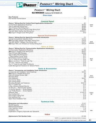
  • 1. ® WWW.CABLEJOINTS.CO.UK THORNE & DERRICK UK TEL 0044 191 490 1547 FAX 0044 477 5371 TEL 0044 117 977 4647 FAX 0044 977 5582 WWW.THORNEANDDERRICK.CO.UK PANDUCT ® Wiring Duct PANDUCT ® Wiring Duct SA-WDCB05 Overview (replaces SA101N64D-LP) Overview New Products . . . . . . . . . . . . . . . . . . . . . . . . . . . . . . . . . . . . . . . . . . . . . . . . . . . . . . . . . . . . . . . . . . . . . . . . . . . . . . . . A2 Part Number Nomenclature . . . . . . . . . . . . . . . . . . . . . . . . . . . . . . . . . . . . . . . . . . . . . . . . . . . . . . . . . . . . . . . . . . . . . . A3 Control Panel PANDUCT ® Wiring Duct for Control Panel Applications Introduction . . . . . . . . . . . . . . . . . . . . . . . . . . . . . . . . . . . . . . B1 Control Panel Applications Roadmap . . . . . . . . . . . . . . . . . . . . . . . . . . . . . . . . . . . . . . . . . . . . . . . . . . . . . . . . . . . . B2-B3 Type G Wide Slot Wiring Duct . . . . . . . . . . . . . . . . . . . . . . . . . . . . . . . . . . . . . . . . . . . . . . . . . . . . . . . . . . . . . . . . . . B4-B5 Type F Narrow Slot Wiring Duct . . . . . . . . . . . . . . . . . . . . . . . . . . . . . . . . . . . . . . . . . . . . . . . . . . . . . . . . . . . . . . . . B6-B7 New Flush Cover Type D Round Hole Wiring Duct . . . . . . . . . . . . . . . . . . . . . . . . . . . . . . . . . . . . . . . . . . . . . . . . . . B8-B9 Type MC Metric Narrow Slot Wiring Duct . . . . . . . . . . . . . . . . . . . . . . . . . . . . . . . . . . . . . . . . . . . . . . . . . . . . . . . . B10-B11 New Type H Hinged Cover Wiring Duct . . . . . . . . . . . . . . . . . . . . . . . . . . . . . . . . . . . . . . . . . . . . . . . . . . . . . . . . . . . . B12 Control Panel Special Environment PANDUCT ® Wiring Duct for Special Environments Introduction . . . . . . . . . . . . . . . . . . . . . . . . . . . . . . . . . . . . . . . . . . C1 Special Environments Selection Chart . . . . . . . . . . . . . . . . . . . . . . . . . . . . . . . . . . . . . . . . . . . . . . . . . . . . . . . . . . . C2-C3 New Type NNC Halogen Free Metric Wiring Duct . . . . . . . . . . . . . . . . . . . . . . . . . . . . . . . . . . . . . . . . . . . . . . . . . . . C4-C5 Type NE NORYL* Halogen Free Wiring Duct. . . . . . . . . . . . . . . . . . . . . . . . . . . . . . . . . . . . . . . . . . . . . . . . . . . . . . . C6-C7 New Type TMC Low Smoke/Low Toxicity Wiring Duct . . . . . . . . . . . . . . . . . . . . . . . . . . . . . . . . . . . . . . . . . . . . . . . . C8-C9 Special Environment Voice & Data PANDUCT ® Wiring Duct for Communication Applications Introduction . . . . . . . . . . . . . . . . . . . . . . . . . . . . . . . . . . . . D1 Communication Applications Roadmap . . . . . . . . . . . . . . . . . . . . . . . . . . . . . . . . . . . . . . . . . . . . . . . . . . . . . . . . . . . D2-D5 New Type H Hinged Cover Wiring Duct . . . . . . . . . . . . . . . . . . . . . . . . . . . . . . . . . . . . . . . . . . . . . . . . . . . . . . . . . . . D6-D7 Type FS Solid Wall Raceway. . . . . . . . . . . . . . . . . . . . . . . . . . . . . . . . . . . . . . . . . . . . . . . . . . . . . . . . . . . . . . . . . . . D8-D9 Type G Wide Slot Wiring Duct . . . . . . . . . . . . . . . . . . . . . . . . . . . . . . . . . . . . . . . . . . . . . . . . . . . . . . . . . . . . . . . . . . . D10 1" Bend Radius Corner Strips . . . . . . . . . . . . . . . . . . . . . . . . . . . . . . . . . . . . . . . . . . . . . . . . . . . . . . . . . . . . . . . . . . . D11 Bend Radius Control Trumpet. . . . . . . . . . . . . . . . . . . . . . . . . . . . . . . . . . . . . . . . . . . . . . . . . . . . . . . . . . . . . . . . . . . . D11 TAK-TY ® Hook & Loop Cable Ties . . . . . . . . . . . . . . . . . . . . . . . . . . . . . . . . . . . . . . . . . . . . . . . . . . . . . . . . . . . . . . . . . D12 New ULTRA-CINCH ™ Hook & Loop Ties . . . . . . . . . . . . . . . . . . . . . . . . . . . . . . . . . . . . . . . . . . . . . . . . . . . . . . . . . . . . . D12 TAK-TAPE ™ Hook & Loop Strips . . . . . . . . . . . . . . . . . . . . . . . . . . . . . . . . . . . . . . . . . . . . . . . . . . . . . . . . . . . . . . . . . . . D13 TAK-TY ® Hook & Loop Cable Tie Mounts. . . . . . . . . . . . . . . . . . . . . . . . . . . . . . . . . . . . . . . . . . . . . . . . . . . . . . . . . . . . D13 Cable Management Solutions for Network Racks . . . . . . . . . . . . . . . . . . . . . . . . . . . . . . . . . . . . . . . . . . . . . . . . . . . . . D14 Voice & Data Tools & Accessories PANDUCT ® Accessories and Installation Tools Introduction . . . . . . . . . . . . . . . . . . . . . . . . . . . . . . . . . . . . . . . . . . . . . E1 Accessories and Installation Tools Roadmap . . . . . . . . . . . . . . . . . . . . . . . . . . . . . . . . . . . . . . . . . . . . . . . . . . . . . . . E2-E3 New Type FL Flexible Wiring Duct . . . . . . . . . . . . . . . . . . . . . . . . . . . . . . . . . . . . . . . . . . . . . . . . . . . . . . . . . . . . . . . . . E4 Solid and Slotted Divider Wall. . . . . . . . . . . . . . . . . . . . . . . . . . . . . . . . . . . . . . . . . . . . . . . . . . . . . . . . . . . . . . . . . . . . . E5 Mounting Base . . . . . . . . . . . . . . . . . . . . . . . . . . . . . . . . . . . . . . . . . . . . . . . . . . . . . . . . . . . . . . . . . . . . . . . . . . . . . . . . E6 Wire Retainers . . . . . . . . . . . . . . . . . . . . . . . . . . . . . . . . . . . . . . . . . . . . . . . . . . . . . . . . . . . . . . . . . . . . . . . . . . . . . E6-E7 Duct Corner Strips . . . . . . . . . . . . . . . . . . . . . . . . . . . . . . . . . . . . . . . . . . . . . . . . . . . . . . . . . . . . . . . . . . . . . . . . . . . . . E8 Duct Joining Strips . . . . . . . . . . . . . . . . . . . . . . . . . . . . . . . . . . . . . . . . . . . . . . . . . . . . . . . . . . . . . . . . . . . . . . . . . . . . . E8 Mounting Brackets and Fasteners . . . . . . . . . . . . . . . . . . . . . . . . . . . . . . . . . . . . . . . . . . . . . . . . . . . . . . . . . . . . . . E9-E10 PAN-TY ® Cable Ties . . . . . . . . . . . . . . . . . . . . . . . . . . . . . . . . . . . . . . . . . . . . . . . . . . . . . . . . . . . . . . . . . . . . . . . . . . . E10 4-Way Adhesive Backed Mounts. . . . . . . . . . . . . . . . . . . . . . . . . . . . . . . . . . . . . . . . . . . . . . . . . . . . . . . . . . . . . . . . . . E11 Tie Mounts — Mechanically Applied . . . . . . . . . . . . . . . . . . . . . . . . . . . . . . . . . . . . . . . . . . . . . . . . . . . . . . . . . . . . . . . E11 Tie Anchor Mounts — Screw Applied . . . . . . . . . . . . . . . . . . . . . . . . . . . . . . . . . . . . . . . . . . . . . . . . . . . . . . . . . . . . . . E12 Low Profile Mounts — Screw Applied . . . . . . . . . . . . . . . . . . . . . . . . . . . . . . . . . . . . . . . . . . . . . . . . . . . . . . . . . . . . . . E12 Adhesive Tape . . . . . . . . . . . . . . . . . . . . . . . . . . . . . . . . . . . . . . . . . . . . . . . . . . . . . . . . . . . . . . . . . . . . . . . . . . . E12-E13 Duct Cutting Tool . . . . . . . . . . . . . . . . . . . . . . . . . . . . . . . . . . . . . . . . . . . . . . . . . . . . . . . . . . . . . . . . . . . . . . . . . . . . . E14 Duct Finger Cutting Tool . . . . . . . . . . . . . . . . . . . . . . . . . . . . . . . . . . . . . . . . . . . . . . . . . . . . . . . . . . . . . . . . . . . . . . . . E14 Duct Notching Tool . . . . . . . . . . . . . . . . . . . . . . . . . . . . . . . . . . . . . . . . . . . . . . . . . . . . . . . . . . . . . . . . . . . . . . . . . . . . E15 Nylon Rivet Installation Tool . . . . . . . . . . . . . . . . . . . . . . . . . . . . . . . . . . . . . . . . . . . . . . . . . . . . . . . . . . . . . . . . . . . . . E15 Tools & Accessories Technical Info Technical Info Dimensions and Information. . . . . . . . . . . . . . . . . . . . . . . . . . . . . . . . . . . . . . . . . . . . . . . . . . . . . . . . . . . . . . . . . . F1-F7 Wirefill Capacity . . . . . . . . . . . . . . . . . . . . . . . . . . . . . . . . . . . . . . . . . . . . . . . . . . . . . . . . . . . . . . . . . . . . . . . . . . . F8-F11 Material Specifications. . . . . . . . . . . . . . . . . . . . . . . . . . . . . . . . . . . . . . . . . . . . . . . . . . . . . . . . . . . . . . . . . . . . . . F12-F13 Color Selection Guide. . . . . . . . . . . . . . . . . . . . . . . . . . . . . . . . . . . . . . . . . . . . . . . . . . . . . . . . . . . . . . . . . . . . . . . . . . F14 Installation Tips . . . . . . . . . . . . . . . . . . . . . . . . . . . . . . . . . . . . . . . . . . . . . . . . . . . . . . . . . . . . . . . . . . . . . . . . . . . . . . F15 Explanation of Agency Approvals and Standards . . . . . . . . . . . . . . . . . . . . . . . . . . . . . . . . . . . . . . . . . . . . . . . . . . F15-F16 Index Index Alphanumeric Part Number Index . . . . . . . . . . . . . . . . . . . . . . . . . . . . . . . . . . . . . . . . . . . . . . . . . . . . . . . . . . . . . G1-G5 *NORYL is a registered trademark of General Electric Company. For service and technical support, call 800-777-3300 (outside the U.S. and Canada, see back cover). A1
  • 2. Overview Type H — Hinged Cover Wiring Duct Wiring Duct from PANDUIT ® Designed for wire management applications where frequent moves, adds, changes or equipment upgrades require repeated, easy and quick access to duct channel. Control Panel See pages B12, D6 & D7 for details. Type FL Special Environment — Flexible Wiring Duct Designed to route and protect wires installed in control panel applications that require flexibility. See page E4 for details. Voice & Data Type NNC — Halogen Free Metric Wiring Duct Designed for panel applications where high temperatures or halogen free requirements exist. See pages C4-C5 for details. Tools & Accessories Type TMC — Low Smoke/Low Toxicity Wiring Duct Designed for wire management applications in public transportation. Technical Info See pages C8-C9 for details. Flush Cover Type D Hole Wiring Duct — Round Improved profile design provides greater wirefill capacity. Index See pages B8-B9 for details. A2
  • 3. ® PANDUCT ® Wiring Duct Overview For over 45 years, PANDUIT ® has been the world leader in the design and manufacture of wiring duct in a wide selection of sizes, styles, colors and materials. The PANDUIT ® name has become synonymous with high quality, innovative wiring duct products used to route, protect and conceal wiring in a wide variety of industrial control and telecommunications applications. PANDUIT ® continues to develop new wiring duct solutions to satisfy the wire management challenges facing our customers worldwide. Control Panel Special Environment Wiring Duct Functional Part Number System Makes Ordering Easy G Type/Style G F FS H D NNC NE MC TMC = = = = = = = = = .5 Nominal Width In. or mm Wide Finger Flush Design Narrow Finger Flush Design Solid Wall Flush Design Wide Finger Hinged Design Round Hole Flush Design Halogen Free Design NORYL * Wide Finger Design Metric Narrow Finger Design Low Smoke Metric Design X .5 LG 6 -A Nominal Height In. or mm Color Length Voice & Data –A = Adhesive Backed = Without Adhesive (leave blank) NM = No Mounting Holes LG DG WH BL IB BR IG = = = = = = = Light Gray Dark Gray White Black Intrinsic Blue Beige International Grey Ft. or M Tools & Accessories Technical Info Index Note: See page F12 for UL94 requirements. *NORYL is a registered trademark of General Electric Company. For service and technical support, call 800-777-3300 (outside the U.S. and Canada, see back cover). A3
  • 4. Overview Wiring Duct Overview Notes Control Panel Special Environment Voice & Data Tools & Accessories Technical Info Index A4
  • 5. Wiring Duct for Control Panel Applications Overview PANDUCT ® Wiring Duct is the premium wire management solution for routing and concealing wiring in control panels. A wide variety of sizes are available to meet the wire capacity needs and space constraints of the smallest wall mounted panels to the largest Control Panel integrated systems. In addition, five innovative wiring duct styles accommodate a variety pe G of specification requirements, control panel designs and post-installation needs. Some of the features and benefits found in all PANDUCT ® Wiring Duct types include: Special Environment Smooth corners and edges will not abrade wiring or irritate hands Integrated nonskid liner and unique cover designs insure the duct cover will not slide once installed or during vibration UL Recognized as meeting the requirements of UL Standard 1565 for Positioning Devices Voice & Data CE compliant for panels that are to be exported to Europe Specially formulated PVC material meets the NFPA79: 2002 flame retardancy requirements for nonmetallic duct in industrial equipment Tools & Accessories PVC material carries a UL94 flammability rating of V-0 for excellent flame retardancy Technical Info Index For service and technical support, call 800-777-3300 (outside the U.S. and Canada, see back cover). B1
  • 6. Wiring Duct for Control Panel Applications Overview Control Panel 3 4 Special Environment 2 a 1 5 Voice & Data a For information on the complete line of PANDUCT Accessories see page E1 ® 1 Type H Hinged Cover Wiring Duct Duct cover hinges open, providing easy access to cabling without the need to remove the cover. Ideal for applications with frequent moves, adds and changes. Tools & Accessories Technical Info PAGE B12 2 Type F Narrow Slot Wiring Duct PAGES B6/B7 Narrow finger and slot design for high-density terminal blocks. Restricted slots retain conductors. Index B2
  • 7. Overview Control Panel 3 Type G Wide Slot Wiring Duct PAGES B4/B5 Wide finger and slot design allows both single conductors and small cable bundles to be easily transitioned from the channel. Fits a wide variety of applications. 4 Type MC Metric Wiring Duct PAGES B10/B11 Narrow finger and slot design for high-density terminal blocks. Metric sizing with DIN style mounting hole pattern meets European specifications. 5 Type D Flush Cover Round Hole Wiring Duct Special Environment Voice & Data Tools & Accessories PAGES B8/B9 Round hole design allows the positioning of wires at various heights when transitioning from the duct. Flush cover design for increased capacity and superior aesthetics. Technical Info Index For service and technical support, call 800-777-3300 (outside the U.S. and Canada, see back cover). B3
  • 8. Wiring Duct Control Panel Overview PANDUCT ® Type G — Wide Slot Wiring Duct • Wide slot/finger design provides greater sidewall rigidity and can be used with a wide range of wire bundle sizes • Made of rigid PVC • UL Recognized continuous use temperature: 50°C (122°F) • UL94 Flammability Rating of V-0 • Provided with mounting holes • Conforms with NFPA 79-2002 section 14.3.1 requirement for flame retardant material Control Panel Duct Size W x H Special Environment Part Number • nonmetallic, non-flame propagating CDS • medium impact resistance • 331 temperature classification • cover removal without tools Voice & Data W H Tools & Accessories Reference Page(s) Color Availability F14 Adhesive Tape Technical Info E12, E13 Dimensions F2 Wirefill Guide F8 Material Specifications F13 Tools & Accessories D11, D12, Section E Installation Tips Index F15 In. mm G.5X.5LG6 G.5X1LG6 G.5X2LG6 G.5X4LG6 G.75X.75LG6 G.75X1LG6 G.75X1.5LG6 G.75X2LG6 G1X1LG6 G1X1.5LG6 G1X2LG6 G1X3LG6 G1X4LG6 G1.5X1LG6 G1.5X1.5LG6 G1.5X2LG6 G1.5X3LG6 G1.5X4LG6 G2X1LG6 G2X1.5LG6 G2X2LG6 G2X3LG6 G2X4LG6 G2X5LG6 G2.5X3LG6 G3X1LG6 G3X2LG6 G3X3LG6 G3X4LG6 G3X5LG6 G4X1.5LG6 G4X2LG6 G4X3LG6 G4X4LG6 G4X5LG6 G6X4LG6 .69 x .60 .69 x 1.06 .69 x 2.03 .69 x 4.10 .93 x .82 .93 x 1.06 .93 x 1.57 .93 x 2.03 1.26 x 1.12 1.26 x 1.62 1.26 x 2.12 1.26 x 3.12 1.26 x 4.10 1.75 x 1.12 1.75 x 1.62 1.75 x 2.12 1.75 x 3.12 1.75 x 4.10 2.25 x 1.12 2.25 x 1.62 2.25 x 2.12 2.25 x 3.12 2.25 x 4.10 2.25 x 5.10 2.75 x 3.12 3.25 x 1.12 3.25 x 2.12 3.25 x 3.12 3.25 x 4.10 3.25 x 5.10 4.25 x 1.62 4.25 x 2.12 4.25 x 3.12 4.25 x 4.10 4.25 x 5.10 6.25 x 4.15 17.5 x 15.2 17.5 x 26.9 17.5 x 51.6 17.5 x 104.1 23.6 x 20.8 23.6 x 26.9 23.6 x 39.9 23.6 x 51.6 32.0 x 28.4 32.0 x 41.1 32.0 x 53.8 32.0 x 79.2 32.0 x 104.1 44.5 x 28.4 44.5 x 41.1 44.5 x 53.8 44.5 x 79.2 44.5 x 104.1 57.2 x 28.4 57.2 x 41.1 57.2 x 53.8 57.2 x 79.2 57.2 x 104.1 57.2 x 129.5 69.9 x 79.2 82.6 x 28.4 82.6 x 53.8 82.6 x 79.2 82.6 x 104.1 82.6 x 129.5 108.0 x 41.1 108.0 x 53.8 108.0 x 79.2 108.0 x 104.1 108.0 x 129.5 158.8 x 105.4 Cover Part Number Duct Cover Std. Ctn. Std. Ctn. Qty. Qty. Length (ft) C.5LG6 120 120 120 60 120 6 C.75LG6 120 120 120 120 120 6 C1LG6 120 120 120 120 60 120 6 C1.5LG6 120 120 120 120 60 120 6 120 6 120 6 120 6 120 6 120 6 C2LG6 C2.5LG6 C3LG6 C4LG6 C6LG6 120 120 120 60 60 60 120 120 120 60 60 60 120 60 60 60 60 60 Part Number shown for LG (Light Gray). For other color availability see Color Selection Guide, page F14. B4 Order number of feet required, in multiples of 6' or Standard Carton Quantity. Base and cover sold separately.
  • 9. ® PANDUCT ® Wiring Duct Overview Non-Slip Cover Specially Formulated Lead-Free Material Rounded Edges V-Shaped Slot Lead-In Flush Cover Design Control Panel Wire Retainer (page E6) Restricted Slot Design Upper Scoreline Wide Finger Design Special Environment Lower Scoreline Features Advantages Benefits Wide finger and slot design Greater rigidity and larger slot width Can be used with a wide range of wire and bundle sizes Smooth rounded edges Exclusive PANDUIT ® process rounds the edges in duct slots and at top of duct fingers Protects hands and wiring/cabling from abrasion Non-slip cover (co-extruded non-slip liner inside duct covers) Will not slide easily when installed on duct base Cover stays in place during shipment, vibration and when in a vertical orientation, eliminating rework Flush cover design Greater capacity than traditional duct designs Can potentially use a smaller size wiring duct for same number of wires Cover sits flush with sidewall Voice & Data Provides a neat and finished appearance Double scoreline Tools & Accessories Upper scoreline at base of finger allows fingers Allows quick modification for larger cabling bundles saving installation time leading to a lower to be broken out without tools installed cost Lower scoreline at base of duct allows sidewall sections to be removed Easier to create tee and corner junctions with full wire carrying capacity Lead-free Eliminates health concerns associated with PVC that contains lead Provides a smooth burr-free edge when sidewalls or fingers are broken out Eliminates the need to deburr saving installation time V-shaped slot lead-in V-shape funnels wires into slot for easier insertion Speeds wire installation Restricted slot design Once inserted wires are retained in the slot with or without the cover being installed Eliminates hassle and saves time during installation and maintenance Specially formulated material Technical Info Index For service and technical support, call 800-777-3300 (outside the U.S. and Canada, see back cover). B5
  • 10. Wiring Duct Control Panel Overview PANDUCT ® Type F — Narrow Slot Wiring Duct • Narrow slot/finger design provides more slots to closer fit the spacing of high-density terminal blocks and other hardware • Made of rigid PVC • UL Recognized continuous use temperature: 50°C (122°F) • UL94 Flammability Rating of V-0 • Provided with mounting holes • Conforms with NFPA 79-2002 section 14.3.1 requirement for flame retardant material Control Panel Special Environment Part Number • nonmetallic, non-flame propagating CDS • medium impact resistance • 331 temperature classification • cover removal without tools Voice & Data .20 (5.0) .50 (12.7) Tools & Accessories W H Technical Info Reference Page(s) Color Availability F14 Adhesive Tape E12, E13 Dimensions F3 Wirefill Guide Cover Part Number F.5X.5LG6 F.5X1LG6 F.75X.75LG6 F.75X1.5LG6 F1X1LG6 F1X1.5LG6 F1X2LG6 F1X3LG6 F1X4LG6 F1.5X1LG6 F1.5X1.5LG6 F1.5X2LG6 F1.5X3LG6 F1.5X4LG6 F2X1LG6 F2X1.5LG6 F2X2LG6 F2X3LG6 F2X4LG6 F2X5LG6 .69 x .60 .69 x 1.06 .93 x .82 .93 x 1.57 1.26 x 1.12 1.26 x 1.62 1.26 x 2.12 1.26 x 3.12 1.26 x 4.10 1.75 x 1.12 1.75 x 1.62 1.75 x 2.12 1.75 x 3.12 1.75 x 4.10 2.25 x 1.12 2.25 x 1.62 2.25 x 2.12 2.25 x 3.12 2.25 x 4.10 2.25 x 5.10 17.5 x 15.2 17.5 x 26.9 23.6 x 20.8 23.6 x 39.9 32.0 x 28.4 32.0 x 41.1 32.0 x 53.8 32.0 x 79.2 32.0 x 104.1 44.5 x 28.4 44.5 x 41.1 44.5 x 53.8 44.5 x 79.2 44.5 x 104.1 57.2 x 28.4 57.2 x 41.1 57.2 x 53.8 57.2 x 79.2 57.2 x 104.1 57.2 x 129.5 F3X1LG6 F3X2LG6 F3X3LG6 F3X4LG6 F3X5LG6 F4X2LG6 F4X3LG6 F4X4LG6 F4X5LG6 3.25 3.25 3.25 3.25 3.25 4.25 4.25 4.25 4.25 82.6 x 28.4 82.6 x 53.8 82.6 x 79.2 C3LG6 82.6 x 104.1 82.6 x 129.5 108.0 x 53.8 108.0 x 79.2 C4LG6 108.0 x 104.1 108.0 x 129.5 x x x x x x x x x 1.12 2.12 3.12 4.10 5.10 2.12 3.12 4.10 5.10 120 6 C.75LG6 120 120 120 6 C1LG6 120 120 120 120 60 120 6 C1.5LG6 120 120 120 120 60 120 6 C2LG6 120 120 120 60 60 60 120 6 120 120 60 60 60 120 6 60 60 60 60 120 6 F13 B6 Installation Tips Length (ft) 120 120 Part Number shown for LG (Light Gray). For other color availability see Color Selection Guide, page F14. Tools & Accessories Section E Index Duct Cover Std. Ctn. Std. Ctn. Qty. Qty. C.5LG6 F8 Material Specifications Duct Size W x H In. mm F15 Order number of feet required, in multiples of 6' or Standard Carton Quantity. Base and cover sold separately.
  • 11. ® PANDUCT ® Wiring Duct Overview Rounded Edges Double Restricted Slot Design Specially Formulated Lead-Free Material Non-Slip Cover Flush Cover Design V-Shaped Slot Lead-In Control Panel Narrow Finger Design Upper Scoreline Lower Scoreline Features Advantages Special Environment Benefits Narrow finger and slot design Provides closer spacing for use with high-density applications Allows further fanning of wires for neater wire management in high-density control panels Smooth rounded edges Exclusive PANDUIT ® process rounds the edges in duct slots and at top of duct fingers Protects hands and wiring/cabling from abrasion Non-slip cover (co-extruded non-slip liner inside duct covers) Will not slide easily when installed on duct base Cover stays in place during shipment, vibration and when in a vertical orientation, eliminating rework Flush cover design Greater capacity than traditional duct designs Can potentially use a smaller size wiring duct for same number of wires Cover sits flush with sidewall Voice & Data Provides a neat and finished appearance Double scoreline Tools & Accessories Upper scoreline at base of finger allows fingers Allows quick modification for larger cabling bundles saving installation time leading to a lower to be broken out without tools installed cost Lower scoreline at base of duct allows complete side wall sections to be removed Easier to create tee and corner junctions with full wire carrying capacity Lead-free Eliminates health concerns associated with PVC that contains lead Provides a smooth burr-free edge when sidewalls or fingers are broken out Eliminates the need to deburr saving installation time V-shaped slot lead-in V-shape funnels wires into slot for easier insertion Speeds wire installation Double restricted slot design Once inserted wires are retained in the slot with or without the cover being installed Eliminates hassle and saves time during installation and maintenance Specially formulated material Second restriction retains cabling within top or Provides a neat and finished appearance bottom portion of slot in larger wiring duct sizes For service and technical support, call 800-777-3300 (outside the U.S. and Canada, see back cover). Technical Info Index B7
  • 12. Wiring Duct Control Panel Overview PANDUCT ® Type D — Flush Cover Round Hole Wiring Duct • Round hole design has multiple rows of holes to retain and support wire at variable heights and positions • Made of rigid PVC • UL Recognized continuous use temperature: 50°C (122°F) • UL94 Flammability Rating of V-0 • Provided with mounting holes • Conforms with NFPA 79-2002 section 14.3.1 requirement for flame retardant material Control Panel Special Environment Part Number • nonmetallic, non-flame propagating CDS • medium impact resistance • 331 temperature classification Voice & Data • cover removal without tools W Tools & Accessories H 1.26 1.26 1.26 1.75 1.75 1.75 2.25 2.25 2.25 2.75 3.25 3.25 3.25 4.25 4.25 4.25 x x x x x x x x x x x x x x x x 2.12 3.12 4.10 2.12 3.12 4.10 2.12 3.12 4.10 3.12 2.12 3.12 4.10 2.12 3.12 4.10 32.0 x 53.8 32.0 x 79.2 32.0 x 104.1 44.5 x 53.8 44.5 x 79.2 44.5 x 104.1 57.2 x 53.8 57.2 x 79.2 57.2 x 104.1 69.9 x 79.2 82.6 x 53.8 82.6 x 79.2 82.6 x 104.1 108.0 x 53.8 108.0 x 79.2 108.0 x 104.1 Cover Part Number Length (ft) C1LG6 120 120 60 120 6 C1.5LG6 120 120 60 120 6 120 6 C2LG6 C2.5LG6 120 60 60 120 120 6 C3LG6 120 60 60 120 6 C4LG6 60 60 60 120 6 Page(s) Color Availability F14 Adhesive Tape E12 Dimensions F2 Wirefill Guide F8 Material Specifications F13 Tools & Accessories Section E Installation Tips F15 Index B8 Duct Cover Std. Ctn. Std. Ctn. Qty. Qty. Part Number shown for LG (Light Gray). For other color availability see Color Selection Guide, page F14. Reference Technical Info D1X2LG6 D1X3LG6 D1X4LG6 D1.5X2LG6 D1.5X3LG6 D1.5X4LG6 D2X2LG6 D2X3LG6 D2X4LG6 D2.5X3LG6 D3X2LG6 D3X3LG6 D3X4LG6 D4X2LG6 D4X3LG6 D4X4LG6 Duct Size W x H In. mm Order number of feet required, in multiples of 6' or Standard Carton Quantity. Base and cover sold separately.
  • 13. ® PANDUCT ® Wiring Duct Overview Non-Slip Cover Rounded Edges Flush Cover Design Specially Formulated Lead-Free Material Control Panel Round Hole Design Special Environment Base Scoreline Features Advantages Benefits Round hole design Retains and supports wires at variable heights Superior aesthetics and wire management and positions with or without the cover installed Flush cover design Greater capacity than traditional duct designs Can potentially use a smaller size wiring duct for same number of wires Cover sits flush with sidewall Provides a neat and finished appearance Non-slip cover (co-extruded non-slip liner inside duct covers) Will not slide easily when installed on duct base Cover stays in place during shipment, vibration and when in a vertical orientation, eliminating rework Smooth rounded edges Exclusive PANDUIT ® process rounds the edges of punched holes Protects hands and wiring/cabling from abrasion Specially formulated material Lead-free Eliminates health concerns associated with PVC that contains lead Provides a smooth burr-free edge when sidewalls are broken out Eliminates the need to deburr saving installation time Scoreline at base of duct allows sidewall sections to be removed Easier to create tee and corner junctions with full wire carrying capacity Base scoreline Voice & Data Tools & Accessories Technical Info Index For service and technical support, call 800-777-3300 (outside the U.S. and Canada, see back cover). B9
  • 14. Wiring Duct Control Panel Overview PANDUCT ® Type MC — Metric Narrow Slot Wiring Duct • CE compliant and metric sizing for control panels intended for European applications • Made of rigid PVC • UL Recognized continuous use temperature: 50°C (122°F) • UL94 Flammability Rating of V-0 • Provided with DIN 43 659 mounting holes • Duct and cover packaged together in 2 meter lengths • Conforms with NFPA 79-2002 section 14.3.1 requirement for flame retardant material Control Panel Special Environment Part Number • nonmetallic, non-flame propagating CDS • medium impact resistance • 331 temperature classification • cover removal without tools Voice & Data 5.0 (.20) 12.5 (.49) Tools & Accessories W H MC25X25IG2 MC25X37IG2 MC25X50IG2 MC25X62IG2 MC25X75IG2 MC37X37IG2 MC37X50IG2 MC37X62IG2 MC37X75IG2 MC50X50IG2 MC50X75IG2 MC50X100IG2 MC62X37IG2 MC62X62IG2 MC75X50IG2 MC75X62IG2 MC75X75IG2 MC75X100IG2 MC100X50IG2 MC100X62IG2 MC100X75IG2 MC100X100IG2 Duct Size W x H mm In. 24.6 24.6 24.6 24.6 24.6 37.1 37.1 37.1 37.1 49.5 49.5 49.5 62.0 62.0 74.7 74.7 74.7 74.7 99.6 99.6 99.6 99.6 x x x x x x x x x x x x x x x x x x x x x x 23.6 35.8 47.8 59.7 72.4 35.8 47.8 59.7 72.4 47.8 72.4 97.8 35.8 59.7 48.0 59.7 72.4 97.8 48.0 59.7 72.4 97.8 Available in IG (International Gray) only. Technical Info F14 Adhesive Tape E12 Dimensions F4 Wirefill Guide F9 Material Specifications B10 Page(s) Color Availability Index Reference F13 Tools & Accessories Section E Installation Tips F15 Order number of pieces required, in multiples of Standard Package Quantity. .97 x .93 .97 x 1.41 .97 x 1.88 .97 x 2.35 .97 x 2.85 1.46 x 1.41 1.46 x 1.88 1.46 x 2.35 1.46 x 2.85 1.95 x 1.89 1.95 x 2.85 1.95 x 3.85 2.44 x 1.41 2.44 x 2.35 2.94 x 1.89 2.94 x 2.35 2.94 x 2.85 2.94 x 3.85 3.92 x 1.89 3.92 x 2.35 3.92 x 2.85 3.92 x 3.85 Replacement Duct Cover Cover Part Std. Ctn. Std. Ctn. Number Qty. Qty. Length (M) C25IG2 20 20 20 20 20 20 2 C37IG2 20 20 20 20 20 2 C50IG2 20 10 10 20 2 C62IG2 20 20 20 2 C75IG2 20 20 10 10 20 2 C100IG2 10 10 10 10 20 2
  • 15. ® PANDUCT ® Wiring Duct Overview Non-Slip Cover Double Restricted Slot Design V-Shaped Slot Lead-In Control Panel Specially Formulated Lead-Free Material Rounded Edges Narrow Finger Design Metric Finger Width and Progression Special Environment Lower Scoreline Upper Scoreline Features Metric size and finger progression Advantages DIN Mounting Hole Pattern Benefits Slot width and pitch may match more closely to Provides a metric sized wiring duct solution for components with metric dimensions applications that specify metric dimensioning, such as when exporting equipment to European countries Narrow finger and slot design Provides closer spacing for use with high-density applications Allows further fanning of wires for neater wire management in high-density control panels DIN 43 659 mounting hole pattern Provides the required mounting hole pattern for use in cabinets which are designed to these standards Meets European standards for use in cabinet applications Smooth rounded edges Exclusive PANDUIT ® process rounds the edges in duct slots and at top of duct fingers Protects hands and wiring/cabling from abrasion Double scoreline Upper scoreline at base of finger allows fingers Allows quick modification for larger cabling bundles saving installation time leading to a lower to be broken out without tools installed cost Voice & Data Lower scoreline at base of duct allows sidewall sections to be removed Easier to create tee and corner junctions with full wire carrying capacity Lead-free Eliminates health concerns associated with PVC that contains lead Provides a smooth burr-free edge when sidewalls or fingers are broken out Eliminates the need to deburr saving installation time Non-slip cover (co-extruded non-slip liner inside duct covers) Will not slide easily when installed on duct base Cover stays in place during shipment, vibration and when in a vertical orientation, eliminating rework Flush cover design Greater capacity than traditional duct designs Can potentially use a smaller size wiring duct for same number of wires Cover sits flush with sidewall Provides a neat and finished appearance Once inserted wires are retained in the slot with or without the cover being installed Eliminates hassle and saves time during installation and maintenance Tools & Accessories Specially formulated material Double restricted slot design Technical Info Index Second restriction retains cabling within top or Provides a neat and finished appearance bottom portion of slot in larger wiring duct sizes For service and technical support, call 800-777-3300 (outside the U.S. and Canada, see back cover). B11
  • 16. Wiring Duct Control Panel Overview PANDUCT ® Type H — Hinged Cover Wiring Duct • • • • Made of rigid PVC UL Recognized continuous use temperature: 50°C (122°F) UL94 Flammability Rating of V-0 Provided with mounting holes Control Panel Duct Size WxH Special Environment Voice & Data Part Number H1.5X2LG6 H1.5X3LG6 H2X2LG6 H2X3LG6 H2X4LG6 H3X3LG6 H3X4LG6 H4X4LG6 H In. mm 1.75 x 1.98 1.75 x 3.06 2.17 x 1.98 2.17 x 3.06 2.17 X 4.10 3.25 x 3.06 3.25 x 4.10 4.25 x 4.10 44.5 x 50.3 44.5 x 77.7 55.1 x 50.3 55.1 x 77.7 55.1 X 104.1 82.6 x 77.7 82.6 x 104.1 108.0 x 104.1 Cover Part Number HC1.5LG6 HC1.5LG6 HC2LG6 HC2LG6 HC2LG6 HC3LG6 HC3LG6 HC4LG6 Available in BL (Black), LG (Light Gray) and WH (White). W Reference Color Availability F14 Adhesive Tape E12 Dimensions F7 Wirefill Guide F9 Material Specifications Tools & Accessories Page(s) F13 Tools & Accessories D11, D12, Section E Installation Tips F15 Technical Info Index B12 Order number of feet required, in multiples of 6' or Standard Carton Quantity. Base and cover sold separately. Duct Cover Std. Ctn. Std. Ctn. Qty. Qty. 120 120 120 60 60 60 60 60 120 120 120 120 120 120 120 60 Length (ft) 6 6 6 6 6 6 6 6
  • 17. Wiring Duct for Special Environments Overview PANDUIT ® offers a selection of special materials in PANDUCT ® Wiring Duct for routing and concealing wiring in special use environments. Special use environments include applications such as transportation, oil and gas platforms, nuclear power plants Control Panel Environment/Material Specifications and semiconductor and electronics manufacturing. Some of the features and benefits found in PANDUCT ® Wiring Duct types for special environments include: Special Environment Specialty materials will not release toxic or corrosive gases that could endanger public safety or damage sensitive electronics, and exhibits excellent flame retardance Flush cover design to maximize capacity over the channel footprint and provide a neater appearance Voice & Data Integrated non-skid liner insures the duct cover will not slide once installed or during vibration Smooth corners and edges will not abrade cabling or irritate hands UL Recognized as meeting the requirements of UL Standard 1565 for Positioning Devices Tools & Accessories CE compliant for panels that are to be exported to Europe Technical Info Index For service and technical support, call 800-777-3300 (outside the U.S. and Canada, see back cover). C1
  • 18. Wiring Duct for Special Environments Overview Control Panel Type NNC Halogen Free Metric Wiring Duct Halogen free material is nontoxic, lead-free, environmentally safe and will not release toxic or corrosive gases that could endanger public safety or damage sensitive electronic equipment Special Environment UL94V-0 Data & Voice Type NE NORYL* Halogen Free Wiring Duct Halogen free material is nontoxic, lead-free, environmentally safe and will not release toxic or corrosive gases that could endanger public safety or damage sensitive electronic equipment UL94V-1 Tools & Accessories Type TMC Low Smoke/Low Toxicity Wiring Duct Low smoke/Low toxicity material emits a low level of toxic fumes and low smoke emissions when burned Technical Info Meets Federal Rail Administration Guidelines and NFPA 130 requirements for all transit vehicles UL94V-0 Index The material is self-extinguishing and has excellent flame retardancy UL94V-0. *NORYL is a registered trademark of General Electric Company. C2 The material does not release dense smoke when burned per ASTM E662 test method. The material does not emit a high volume of toxic gases when burned per Boeing and Airbus test methods.
  • 19. Overview Control Panel Environment/Material Specifications Typical Applications PAGES C4/C5 Semiconductor Manufacturing Ship Building Nuclear Power Plants Oil Platforms Environment/Material Specifications Typical Applications Special Environment PAGES C6/C7 Data & Voice Semiconductor Manufacturing Ship Building Nuclear Power Plants Oil Platforms Tools & Accessories Environment/Material Specifications Typical Applications PAGES C8/C9 Passenger Rail Cars Other Transportation Vehicles Technical Info The material contains no fluorine, bromide or chlorine and will not emit any corrosive or toxic gases when burned per IEC 60754-2 test method. Material is rated for a continuous use temperature above 75˚ C (167˚ F). Index For service and technical support, call 800-777-3300 (outside the U.S. and Canada, see back cover). C3
  • 20. Wiring Duct Special Environments Overview PANDUCT ® Type NNC — Halogen Free Metric Wiring Duct • Made of halogen free material and verified with IEC 60754-2 test method (test on gases evolved during combustion of electric cables) • UL Recognized continuous use temperature: 95°C (203°F) • UL94 Flammability Rating of V-0 • Conforms with NFPA 79-2002 section 14.3.1 requirement for flame retardant material • Provided with DIN 43 659 mounting holes • Metric sizing and finger progression • Duct and cover packaged together in 2 meter lengths Control Panel Special Environment Duct Size WxH mm In. Part Number • nonmetallic, non-flame propagating CDS • medium impact resistance • 211 temperature classification • cover removal without tools Data & Voice W H NNC25X25LG2 NNC25X37LG2 NNC25X50LG2 NNC25X75LG2 NNC37X37LG2 NNC37X50LG2 NNC37X75LG2 NNC50X50LG2 NNC50X75LG2 NNC50X100LG2 NNC75X75LG2 NNC100X50LG2 NNC100X75LG2 NNC100X100LG2 24.6 24.6 24.6 24.6 37.1 37.1 37.1 49.5 49.5 49.5 74.7 99.6 99.6 99.6 Technical Info Reference Page(s) Color Availability F14 Adhesive Tape E12 Dimensions F5 Wirefill Guide F9 Material Specifications F13 Tools and Accessories Installation Tips C4 23.6 35.8 47.8 72.4 35.8 47.8 72.4 47.8 72.4 97.8 72.4 47.8 72.4 97.8 .97 x .93 .97 x 1.41 .97 x 1.88 .97 x 2.85 1.46 x 1.41 1.46 x 1.88 1.46 x 2.85 1.95 x 1.88 1.95 x 2.85 1.95 x 3.85 2.94 x 2.85 3.92 x 1.88 3.92 x 2.85 3.92 x 3.85 Duct Cover Std. Ctn. Std. Ctn. Qty. Qty. Length (M) NC25LG2 20 20 20 20 20 20 20 20 2 NC37LG2 20 20 20 20 20 20 2 20 10 10 10 20 20 20 20 10 10 10 20 20 20 NC50LG2 NC75LG2 NC100LG2 2 2 2 Available in LG (Light Gray) and WH (White). Do not allow cutting, tapping or cleaning fluids that contain hydrocarbons to come in contact with Type NNC Wiring Duct as it will cause stress cracking. See page F15 for a list of chemicals to avoid. Tools & Accessories Index x x x x x x x x x x x x x x Replacement Cover Part Number E9, E10, E13, E14 F15 Order number of meters required, in multiples of Standard Carton Quantity.
  • 21. ® PANDUCT ® Wiring Duct Overview Rounded Edges V-Shaped Slot Lead-In Halogen Free Non-Slip Cover Liner Restricted Slots Control Panel Specially Formulated Halogen Free Material Metric Finger Width and Progression Special Environment Upper Scoreline Features Lower Scoreline Advantages Benefits Material is nontoxic, lead-free, environmentally safe and will not release toxic or corrosive gases that could endanger public safety or damage sensitive electronics Ideal for application where public safety during a fire is a concern Greater resistance to heat than PVC Suitable for panel applications where high temperatures exist UL94V-0 material flame rating The V-0 flammability rating exceeds the rating of most other halogen free duct materials Material is self-extinguishing and exhibits the highest flame retardance meeting more electrical panel applications Halogen free non-slip cover liner Cover will not slide easily when installed on duct base Cover stays in place during shipment, vibration and when in a vertical orientation, eliminating rework Co-extruded liner made from halogen free material Liner will not emit corrosive or toxic gases DIN 43 659 mounting hole pattern Provides the required mounting hole pattern for use in cabinets which are designed to these standards Meets European standards for use in cabinet applications Smooth rounded edges Exclusive PANDUIT ® process rounds the edges in duct slots and at top of duct fingers Protects hands and wiring/cabling from abrasion Double scoreline Upper scoreline at base of finger allows fingers Allows quick modification for larger cabling bundles saving installation time leading to a lower to be broken out without tools installed cost Halogen free modified PPO material Material is recyclable and suitable for applications requiring eco-friendly materials Lower scoreline at base of duct allows sidewall sections to be removed Easier to create tee and corner junctions with full wire carrying capacity V-shaped slot lead-in V-shape funnels wires into slot for easier insertion Once inserted wires are retained in the slot with or without the cover being installed Provides a neat and finished appearance Duct and cover packaged together Fewer part numbers to stock and manage Reduced inventory cost Metric size and finger progression Technical Info Eliminates hassle and saves time during installation and maintenance Second restriction retains cabling within top or bottom portion of slot in larger wiring duct sizes Tools & Accessories Speeds wire installation Double restricted slot design Voice & Data Slot width and pitch may match more closely to Provides a metric sized wiring duct solution for components with metric dimensions applications that specify metric dimensioning, such as when exporting equipment to European countries For service and technical support, call 800-777-3300 (outside the U.S. and Canada, see back cover). Index C5
  • 22. Wiring Duct Special Environments Overview PANDUCT ® Type NE — NORYL* Halogen Free Wiring Duct • Made of halogen free NORYL* material • UL94 Flammability Rating of V-1 • Provided with mounting holes Control Panel Special Environment Part Number Duct Size W x H In. mm • medium impact resistance • 211 temperature classification • cover removal without tools Data & Voice Tools & Accessories W H Page(s) Color Availability F14 F13 Tools and Accessories Section E Installation Tips F15 *NORYL is a registered trademark of General Electric Company. C6 x x x x 2.06 3.06 4.06 5.06 Duct Cover Std. Ctn. Std. Ctn. Qty. Qty. Length (ft) NC.5WH6 120 120 120 6 NC1WH6 120 120 120 120 60 120 6 NC1.5WH6 120 120 120 60 120 6 120 6 NC2WH6 NC2.5WH6 120 120 60 60 120 120 6 NC3WH6 120 120 60 60 60 120 6 105.2 x 52.3 105.2 x 77.7 NC4WH6 105.2 x 103.1 105.2 x 128.5 60 60 60 60 120 6 Available in WH (White) only. Do not allow cutting, tapping or cleaning fluids that contain hydrocarbons to come in contact with Type NE Wiring Duct as it will cause stress cracking. See page F15 for a list of chemicals to avoid. F10 Material Specifications 4.14 4.14 4.14 4.14 F6 Wirefill Guide 16.0 x 14.2 16.0 x 26.9 29.0 x 26.9 29.0 x 41.1 29.0 x 52.3 29.0 x 77.7 29.0 x 103.1 41.7 x 41.1 41.7 x 52.3 41.7 x 77.7 41.7 x 103.1 54.4 x 26.9 54.4 x 52.3 54.4 x 77.7 54.4 x 103.1 67.1 x 77.7 79.8 x 26.9 79.8 x 52.3 79.8 x 77.7 79.8 x 103.1 79.8 x 128.5 E12, E13 Dimensions Index Reference Adhesive Tape Technical Info .63 x .56 .63 x 1.06 1.14 x 1.06 1.14 x 1.62 1.14 x 2.06 1.14 x 3.06 1.14 x 4.06 1.64 x 1.62 1.64 x 2.06 1.64 x 3.06 1.64 x 4.06 2.14 x 1.06 2.14 x 2.06 2.14 x 3.06 2.14 x 4.06 2.64 x 3.06 3.14 x 1.06 3.14 x 2.06 3.14 x 3.06 3.14 x 4.06 3.14 x 5.06 NE4X2WH6 NE4X3WH6 NE4X4WH6 NE4X5WH6 • nonmetallic, non-flame propagating CDS NE.5X.5WH6 NE.5X1WH6 NE1X1WH6 NE1X1.5WH6 NE1X2WH6 NE1X3WH6 NE1X4WH6 NE1.5X1.5WH6 NE1.5X2WH6 NE1.5X3WH6 NE1.5X4WH6 NE2X1WH6 NE2X2WH6 NE2X3WH6 NE2X4WH6 NE2.5X3WH6 NE3X1WH6 NE3X2WH6 NE3X3WH6 NE3X4WH6 NE3X5WH6 Cover Part Number Order number of pieces required, in multiples of Standard Package Quantity.
  • 23. ® PANDUCT ® Wiring Duct Overview V-Shaped Slot Lead-In Non-Slip Cover Halogen Free Material Restricted Slot Design Control Panel Rounded Edges Special Environment Base Scoreline Features Advantages Benefits Material is nontoxic, lead-free, environmentally safe and will not release toxic or corrosive gases that could endanger public safety or damage sensitive electronics Ideal for applications where public safety during a fire is a concern Greater resistance to heat than PVC Suitable for panel applications where high temperatures exist Smooth rounded edges Exclusive PANDUIT ® process rounds the edges in duct slots and at top of duct fingers Protects hands and wiring/cabling from abrasion Non-slip cover (co-extruded non-slip liner inside duct covers) Will not slide easily when installed on duct base Cover stays in place during shipment, vibration and when in a vertical orientation, eliminating rework Halogen free NORYL* material Material is recyclable and suitable for applications requiring eco-friendly materials Base scoreline Scoreline at base of duct allows sidewall sections to be removed V-shape funnels wires into slot for easier insertion Speeds wire installation Restricted slot design Once inserted wires are retained in the slot with or without the cover being installed Tools & Accessories Easier to create tee and corner junctions with full wire carrying capacity V-shaped slot lead-in Voice & Data Eliminates hassle and saves time during installation and maintenance Technical Info Index *NORYL is a registered trademark of General Electric Company. For service and technical support, call 800-777-3300 (outside the U.S. and Canada, see back cover). C7
  • 24. Overview Wiring Duct Special Environments PANDUCT ® Type TMC — Low Smoke/Low Toxicity Wiring Duct • • • • Made of low smoke, low toxicity and low flammability material UL Recognized continuous use temperature: 80°C (176°F) UL94 Flammability Rating of V-0 Conforms with NFPA 79-2002 section 14.3.1 requirement for flame retardant material • Provided with DIN 43 659 mounting holes • Metric sizing and finger progression • Duct and cover packaged together in 2 meter lengths Control Panel Duct Size W x H Special Environment Part Number • nonmetallic, non-flame propagating CDS • medium impact resistance • 331 temperature classification • cover removal without tools 24.6 37.1 49.5 74.7 74.7 99.6 99.6 x x x x x x x 35.8 35.8 48.0 48.0 73.2 48.0 73.2 In. .97 x 1.41 1.46 x 1.41 1.95 x 1.89 2.94 x 1.89 2.94 x 2.88 3.92 x 1.89 3.92 x 2.88 Duct Cover Std. Ctn. Std. Ctn. Qty. Qty. Length (M) TC25BR2 TC37BR2 TC50BR2 20 20 20 20 20 20 2 2 2 TC75BR2 20 10 20 2 TC100BR2 10 10 20 2 Available in BR (Natural Beige) only. Data & Voice Reference Page(s) Color Availability F14 Adhesive Tape E12 Dimensions F4 Wirefill Guide F9 Material Specifications F13 Tools and Accessories Section E Installation Tips Tools & Accessories TMC25X37BR2 TMC37X37BR2 TMC50X50BR2 TMC75X50BR2 TMC75X75BR2 TMC100X50BR2 TMC100X75BR2 mm Replacement Cover Part Number F15 W H PANDUCT ® Type TMC — Low Smoke / Low Toxicity Solid Divider Wall Technical Info • TMC Divider Wall can be mounted inside TMC Wiring Duct to create multiple channels • Low smoke, low toxicity and low flammability material • Simply install the divider wall base when mounting the duct and snap the divider wall onto mounting base (part No. DB-C) Part Number Index For Nominal Duct Height (mm) Std. Pkg. Qty. TMC50DW2 TMC75DW2 50 75 2 2 Std. Ctn. Qty. Length (M) 20 20 2 2 NOTE: Must be used with Mounting Base (DB-C) which is sold separately. Install mounting bases to the duct channel, locate within 2" of each divider wall end and at least every 12" along the length. C8 Order number of meters required, in multiples of Standard Carton Quantity.
  • 25. ® PANDUCT ® Wiring Duct Overview Rounded Edges Double Restricted Slot Control Panel V-Shaped Slot Lead-In Low Smoke Low Toxicity Material Metric Finger Width and Progression Special Environment Lower Scoreline Upper Scoreline Features Advantages Benefits Material emits a low level of toxic fumes when burned per Boeing BSS 7239 and Airbus ATS 1000.01 test methods Meets the low toxicity requirements of many Mass Transit OEM applications Passenger safety in the case of a fire Zero flame spread per ASTM E 162 test method Meets the Federal Rail Administration Guidelines and National Fire Protection Agency NFPA 130 standards for Mass Transit OEM applications Material is self-extinguishing and exhibits excellent flame retardance Excellent fire resistance Passenger safety in the case of a fire Material is 40% lighter than aluminum Contributes to a reduction in vehicle weight lending to energy savings Easier to handle than metal channel and can be field cut and installed Reduces installer fatigue and simplifies installation steps leading to a lower installed cost Cuts leave smooth, burr-free edges Eliminates need to deburr cut edges simplifying installation and reducing concern of wire abrasion Nonconductive Lightweight nonmetallic material Passenger safety in the case of a fire Material maintains a UL94V-0 flammability rating Low flammability material Meets the Federal Rail Administration Guidelines and National Fire Protection Agency NFPA 130 standards for Mass Transit OEM applications Emits low levels of toxic fumes when burned Low toxicity material Low smoke emissions material per ASTM E 662 test method Low smoke emissions result in improved visibility during a fire Low smoke emission material Grounding and bonding of the channel is not required simplifying installation Non-slip cover (co-extruded nonslip liner inside duct covers) Will not slide easily when installed on duct base Exclusive PANDUIT ® process rounds the edges in duct slots and at top of duct fingers Upper scoreline at base of finger allows fingers Allows quick modification for larger cabling bundles saving installation time leading to a lower to be broken out without tools installed cost Technical Info Protects hands and wiring/cabling from abrasion Double scoreline Tools & Accessories Cover stays in place during shipment, vibration and when in a vertical orientation, eliminating rework Smooth rounded edges Voice & Data Lower scoreline at base of duct allows sidewall sections to be removed Index Easier to create tee and corner junctions with full wire carrying capacity For service and technical support, call 800-777-3300 (outside the U.S. and Canada, see back cover). C9
  • 26. Overview Wiring Duct Special Environments Notes Control Panel Special Environment Data & Voice Tools & Accessories Technical Info Index C10
  • 27. Wiring Duct for Voice & Data Applications Overview PANDUIT ® offers PANDUCT ® Wiring Duct styles specially suited for routing and concealing cabling in communications applications. Applications include wire management for backboard mounted voice, data and video applications, cord management near workstations, use Control Panel inside communications cabinets and other general purpose applications. Some of the features and benefits found in PANDUCT ® Wiring Duct types for communications applications include: Special Environment Black color to compliment the look of telecommunications racks and hardware PANDUIT ® exclusive wide slot/wide finger progression and hinging cover provides easy access ideal for frequent moves, adds and changes Voice & Data Solid wall raceway completely conceals cabling in applications where frequent breakouts are not required Bend radius control accessories for cabling as required in NFPA 79-2002 section 14.1.4.9 and TIA/EIA 568-B and 569-A Tools & Accessories Smooth corners and edges that will not abrade cabling or irritate hands UL94 flammability rating of V-0 for excellent flame retardancy Technical Info Index For service and technical support, call 800-777-3300 (outside the U.S. and Canada, see back cover). D1
  • 28. Wiring Duct for Backboard Applications Overview Control Panel 1 Special Environment Voice & Data 2 Tools & Accessories 3 Technical Info 4 Index For Cable Management Solutions for Network Racks see page D14. D2
  • 29. Overview 1 Type H Hinged Cover Wiring Duct PAGE D6/D7 Features wide slot/wide finger progression for communications cabling. Provides easy access to cabling for moves, adds and changes. 2 Bend Radius Control Corner Strips PAGE D11 Snap to duct walls at tee intersections and right angles to provide cable protection around corners. 3 Bend Radius Control Trumpet ™ Special Environment Voice & Data PAGE D11 Provides a smooth transition from hardware to duct channel. 4 TAK-TAPE Hook & Loop Strips Control Panel PAGE D13 Secure cable bundles entering or exiting the wiring duct. Tape roll allows any size cable bundle to be easily secured. For service and technical support, call 800-777-3300 (outside the U.S. and Canada, see back cover). Tools & Accessories Technical Info Index D3
  • 30. Cord Management at the Workstation Overview Control Panel Special Environment 2 Voice & Data 1 3 Tools & Accessories 4 Technical Info Index ® For information on the complete line of PANDUCT Wiring Duct see page B1 D4
  • 31. Overview 1 Type H Hinged Cover Wiring Duct PAGE D6/D7 Contain cable slack at the workstation. Hinged cover provides easy access to cabling for moves, adds and changes. 2 Wire Retainers PAGE D12 Contain cabling when duct cover is opened. Wire retainers snap easily between duct fingers. 3 ULTRA-CINCH Hook & Loop Ties ™ TAK-TY Hook & Loop Cable Ties ® ® Special Environment Voice & Data PAGE D12 Very easy to release and reuse, making them ideal for applications where changes are anticipated or continuous access is required. 4 TAK-TY Hook & Loop Cable Tie Mounts Control Panel PAGE D13 Route and secure sensitive communication cabling without damaging the cable bundles. Optional adhesive backed mounts can be easily mounted within the wiring duct base. For service and technical support, call 800-777-3300 (outside the U.S. and Canada, see back cover). Tools & Accessories Technical Info Index D5
  • 32. Wiring Duct Voice & Data Overview PANDUCT ® Type H — Hinged Cover Wiring Duct • • • • Made of rigid PVC UL Recognized continuous use temperature: 50°C (122°F) UL94 Flammability Rating of V-0 Provided with mounting holes Control Panel Duct Size WxH Special Environment Part Number H1.5X2BL6 H1.5X3BL6 H2X2BL6 H2X3BL6 H2X4BL6 H3X3BL6 H3X4BL6 H4X4BL6 H Voice & Data In. 1.75 1.75 2.17 2.17 2.17 3.25 3.25 4.25 x x x x x x x x 1.98 3.06 1.98 3.06 4.10 3.06 4.10 4.10 mm 44.5 x 50.3 44.5 x 77.7 55.1 x 50.3 55.1 x 77.7 55.1 x 104.1 82.6 x 77.7 82.6 x 104.1 108.0 x 104.1 Cover Part Number HC1.5BL6 HC1.5BL6 HC2BL6 HC2BL6 HC2BL6 HC3BL6 HC3BL6 HC4BL6 Available in BL (Black), LG (Light Gray) and WH (White). W Reference Color Availability F14 Adhesive Tape E12 Dimensions F7 Wirefill Guide F9 Material Specifications Tools & Accessories Page(s) F13 Tools & Accessories D11, D12, Section E Technical Info Installation Tips F15 Index D6 Order number of feet required, in multiples of 6' or Standard Carton Quantity. Base and cover sold separately. Duct Cover Std. Ctn. Std. Ctn. Qty. Qty. 120 120 120 60 60 60 60 60 120 120 120 120 120 120 120 60 Length (ft) 6 6 6 6 6 6 6 6
  • 33. ® PANDUCT ® Wiring Duct Overview Cover Retention Flange Specially Formulated Lead-Free Material Integrated Hinged Cover Design Dual-Sided Hinge Control Panel Rounded Edges Restricted Slot Design Upper Scoreline Features Special Environment Lower Scoreline Advantages Benefits PANDUIT ® exclusive design provides access to duct channel without the need to completely remove and reinstall the cover Covers are less likely to be misplaced maintaining a neater appearance to the installation Dual-sided hinge Cover can hinge open up to 100° from either sidewall of duct base Provides full access to the channel without the need to remove the cover Cover retention flange Enables easier cover engagement with the base Provides easy snap-on installation Engages cover securely with base Cover stays in place during vibration and when in a vertical orientation, eliminating rework Allows cover to open and stay in position at any angle Cover will function and stay open regardless of vertical or horizontal position duct is mounted in Cover removal rib Provides surface to grip cover Cover is easy to open or remove Smooth rounded edges Exclusive PANDUIT ® process rounds the edges in duct slots and at top of duct fingers Protects hands and wiring/cabling from abrasion Double scoreline Upper scoreline at base of finger allows fingers Allows quick modification for larger cabling bundles saving installation time leading to a lower to be broken out without tools installed cost Integrated hinged cover design Voice & Data Lower scoreline at base of duct allows sidewall sections to be removed Easier to create tee and corner junctions with full wire carrying capacity Restricted slot design Once inserted wires are retained in the slot with or without the cover being installed Eliminates hassle and saves time during installation and maintenance Specially formulated material Lead-free Removes health concerns associated with PVC that contains lead Provides a smooth burr-free edge when sidewalls or fingers are broken out Tools & Accessories Eliminates the need to deburr saving installation time Technical Info Index For service and technical support, call 800-777-3300 (outside the U.S. and Canada, see back cover). D7
  • 34. Wiring Duct Voice & Data Overview PANDUCT ® Type FS — Solid Wall Raceway • Solid wall design fully encloses cables providing maximum protection and aesthetics • Made of rigid PVC • UL Recognized continuous use temperature: 50°C (122°F) • UL94 Flammability Rating of V-0 • Supplied without mounting holes Control Panel Duct Size W x H Special Environment Cover Part Number Part Number In. mm > FS.5X.5LG6NM .69 x .60 .69 x 1.06 .93 x .82 1.26 x 1.12 1.26 x 1.62 1.26 x 2.12 1.26 x 3.12 1.26 x 4.10 1.75 x 1.12 1.75 x 1.62 1.75 x 2.12 1.75 x 3.12 2.25 x 1.12 2.25 x 1.62 2.25 x 2.12 2.25 x 3.12 2.25 x 4.10 3.25 x 1.12 3.25 x 2.12 3.25 x 3.12 3.25 x 4.10 17.5 x 15.2 17.5 x 26.9 23.6 x 20.8 32.0 x 28.4 32.0 x 41.1 32.0 x 53.8 32.0 x 79.2 32.0 x 104.1 44.5 x 28.4 44.5 x 41.1 44.5 x 53.8 44.5 x 79.2 57.2 x 28.4 57.2 x 41.1 57.2 x 53.8 57.2 x 79.2 57.2 x 104.1 82.6 x 28.4 82.6 x 53.8 82.6 x 79.2 82.6 x 104.1 3.25 4.25 4.25 4.25 4.25 6.25 82.6 x 129.5 108.0 x 53.8 108.0 x 79.2 C4LG6 108.0 x 104.1 108.0 x 129.5 158.8 x 105.4 C6LG6 > FS.5X1LG6NM FS.75X.75LG6NM • nonmetallic, non-flame propagating CDS > FS1X1LG6NM • medium impact resistance > FS1X1.5LG6NM • 331 temperature classification • cover removal without tools • IP40 degree of protection Voice & Data > > > > W > > H > Tools & Accessories > > > FS1X2LG6NM FS1X3LG6NM FS1X4LG6NM FS1.5X1LG6NM FS1.5X1.5LG6NM FS1.5X2LG6NM FS1.5X3LG6NM FS2X1LG6NM FS2X1.5LG6NM FS2X2LG6NM FS2X3LG6NM FS2X4LG6NM FS3X1LG6NM FS3X2LG6NM FS3X3LG6NM FS3X4LG6NM Reference Color Availability F14 > FS4X2LG6NM Adhesive Tape E12, E13 > FS4X3LG6NM Dimensions Technical Info Page(s) F3 > FS4X4LG6NM Wirefill Guide F8 Material Specifications F13 FS3X5LG6NM > FS4X5LG6NM > FS6X4LG6NM x x x x x x 5.10 2.12 3.12 4.10 5.10 4.15 C.5LG6 C.75LG6 120 6 120 6 C1LG6 120 6 C1.5LG6 120 120 120 120 120 6 C2LG6 120 120 120 60 60 120 6 120 6 120 6 120 6 C3LG6 120 120 60 60 60 60 60 60 60 60 >SYMBOL indicates parts available with mounting holes. Remove NM from part number. Part Number shown for LG (Light Gray). For other color availability see Color Selection Guide, page F15. F15 Index D8 120 120 120 Length (ft) 120 120 120 120 60 Tools & Accessories D11, D12, Section E Installation Tips Duct Cover Std. Ctn. Std. Ctn. Qty. Qty. Order number of feet required, in multiples of 6' or Standard Carton Quantity. Base and cover sold separately.
  • 35. ® PANDUCT ® Wiring Duct Overview Specially Formulated Lead-Free Material Non-Slip Cover Solid Wall Design Control Panel Flush Cover Design Special Environment Scoreline at Base Features Advantages Benefits Solid wall design Fully encloses the cables providing maximum protection Provides a more aesthetically pleasing solution for applications that do not require frequent cable breakouts Flush cover design Greater capacity than traditional duct designs Can potentially use a smaller size wiring duct for same number of wires Cover sits flush with sidewall Provides a neat and finished appearance Base scoreline Scoreline at base of duct allows sidewall sections to be removed Easier to create tee and corner junctions with full wire carrying capacity Non-slip cover (co-extruded non-slip liner inside duct covers) Will not slide easily when installed on duct base Cover stays in place during shipment, vibration and when in a vertical orientation, eliminating rework Specially formulated material Lead-free Eliminates health concerns associated with PVC that contains lead Provides a smooth burr-free edge when sidewalls are broken out Eliminates the need to deburr saving installation time Voice & Data Tools & Accessories Technical Info Index For service and technical support, call 800-777-3300 (outside the U.S. and Canada, see back cover). D9
  • 36. Wiring Duct Voice & Data Overview PANDUCT ® Type G — Wide Slot Wiring Duct • Wide selection of sizes available in black color to compliment the look of telecommunications racks and hardware • Made of rigid PVC • UL Recognized continuous use temperature: 50°C (122°F) • UL94 Flammability Rating of V-0 • Provided with mounting holes • Conforms with NFPA 79-2002 section 14.3.1 requirement for flame retardant material Control Panel Special Environment Part Number • nonmetallic, non-flame propagating CDS • medium impact resistance • 331 temperature classification • cover removal without tools Voice & Data W H Tools & Accessories Reference Page(s) Color Availability F14 Adhesive Tape Technical Info 23.6 x 51.6 32.0 x 28.4 32.0 x 41.1 32.0 x 53.8 32.0 x 79.2 32.0 x 104.1 44.5 x 41.1 44.5 x 53.8 44.5 x 79.2 44.5 x 104.1 57.2 x 28.4 57.2 x 53.8 57.2 x 79.2 57.2 x 104.1 69.9 x 79.2 82.6 x 53.8 82.6 x 79.2 82.6 x 104.1 108.0 x 53.8 108.0 x 79.2 108.0 x 104.1 G4X5BL6 4.25 x 5.10 108.0 x 129.5 120 6 C1BL6 120 120 120 120 60 120 6 C1.5BL6 120 120 120 60 120 6 120 6 120 6 120 6 120 6 C2BL6 C2.5BL6 C3BL6 C4BL6 120 120 60 60 120 120 60 60 60 60 60 60 Part Number shown for BL (Black). For other color availability see Color Selection Guide, page F14. F13 F15 Index D10 Length (ft) 120 Tools & Accessories D11, D12, Section E Installation Tips Duct Cover Std. Ctn. Std. Ctn. Qty. Qty. C.75BL6 F8 Material Specifications .93 x 2.03 1.26 x 1.12 1.26 x 1.62 1.26 x 2.12 1.26 x 3.12 1.26 x 4.10 1.75 x 1.62 1.75 x 2.12 1.75 x 3.12 1.75 x 4.10 2.25 x 1.12 2.25 x 2.12 2.25 x 3.12 2.25 x 4.10 2.75 x 3.12 3.25 x 2.12 3.25 x 3.12 3.25 x 4.10 4.25 x 2.12 4.25 x 3.12 4.25 x 4.10 F2 Wirefill Guide G.75X2BL6 G1X1BL6 G1X1.5BL6 G1X2BL6 G1X3BL6 G1X4BL6 G1.5X1.5BL6 G1.5X2BL6 G1.5X3BL6 G1.5X4BL6 G2X1BL6 G2X2BL6 G2X3BL6 G2X4BL6 G2.5X3BL6 G3X2BL6 G3X3BL6 G3X4BL6 G4X2BL6 G4X3BL6 G4X4BL6 Cover Part Number E12, E13 Dimensions Duct Size W x H In. mm Order number of feet required, in multiples of 6' or Standard Carton Quantity. Base and cover sold separately.
  • 37. ® PANDUCT ® Wiring Duct Overview PANDUCT ® Duct Corner Strip with 1" Bend Radius Control • Creates a strong rigid corner at wiring duct junctions • Provides bend radius protection for cabling as required in NFPA 79-2002 section 14.1.4.9 and TIA/EIA 568-B and 569-A • Available in five pre-cut sizes and 6' lengths that can be cut-to-size to meet any size requirement • Easy to install two-piece design • Compatible with all styles of PANDUIT ® Wiring Duct • Made of PVC material Part Number Part Description For Duct Height In. mm Control Panel Std. Std. Pkg. Ctn. Color Qty. Qty. 6 Foot Lengths for use with all Types of PVC Wiring Duct* CSC1LG6 Cut-to-size 6 foot corner strip with a 1" bend radius. CSC1WH6 CSC1BL6 All sizes (Cut to duct height) All sizes (Cut to duct height) Light Gray 6 120 White Black 6 6 120 120 Special Environment Pre-Cut Pieces for use with all Types of PVC Wiring Duct^ CSPC1LG-Q 1" bend radius corner strip pre-cut for 1" wall height. 1.00 25.4 Light Gray 25 250 CSPC1.5LG-Q 1" bend radius corner strip pre-cut for 1.5" wall height (2.0" Type H Duct). 1.50 38.1 Light Gray 25 250 CSPC2LG-Q 1" bend radius corner strip pre-cut for 2" wall height. 2.00 50.8 Light Gray 25 250 CSPC3LG-Q 1" bend radius corner strip pre-cut for 3" wall height. 3.00 76.2 Light Gray 25 250 CSPC4LG-Q 1" bend radius corner strip pre-cut for 4" wall height (4.0" Type H Duct). 4.00 101.6 Light Gray 25 250 Voice & Data *Order number of feet required, in multiples of 6' or Standard Package Quantity. ^Order number of pieces required in multiples of Standard Package Quantity. Pre-cut pieces available in LG (Light Gray) only. Tools & Accessories Bend Radius Control Trumpet • Provides method to transition cabling from wall mounted hardware to wiring duct channel • Provides bend radius protection for cabling as required in NFPA 79-2002 section 14.1.4.9 and TIA/EIA 568-B and 569-A • Made of ABS material Part Number Part Description For Duct Height In. mm Std. Std. Pkg. Ctn. Qty. Qty. TRC2BL TRC4BL TRC2HDBL 2.00 50.8 1 10 TRC4BL Bend radius control trumpet for exiting at the sidewall of 4" wall heights of Type G or Type FS Wiring Duct channels. 4.00 101.6 1 10 TRC2HDBL TRC2BL Bend radius control trumpet for exiting at the sidewall of 2" wall heights of Type G or Type FS Wiring Duct channels. Bend radius control trumpet for exiting at the sidewall of 2" wall heights of Type H Hinged Cover Wiring Duct channels. 2.00 50.8 1 10 Technical Info Index Order number of pieces required in multiples of Standard Package Quantity. Available in BL (Black) only. For service and technical support, call 800-777-3300 (outside the U.S. and Canada, see back cover). D11
  • 38. Overview Wiring Duct Voice & Data TAK-TY ® Hook & Loop Cable Ties Control Panel • • • • • • Releasable and reusable hundreds of times No risk of over-tensioning and damaging high performance cabling No installation tool needed Operating temperature range: 0 to 220°F Several styles (HLS, HLM, HLT, and HLC) available to suit a variety of applications Select styles (HLSP and HLTP) are UL Listed for use in air handling space applications per NEC Section 300-22 (C) and (D) Part Number Part Description Max. Bundle Diameter In. mm Min. Loop Std. Std. Tensile Length Pkg. Ctn. Str. (In.) Qty. Qty. (Lbs.) 15' & 75' Rolls — Can be cut to desired length, eliminating waste HLS-15R0 15' roll, .75" width, Standard, Black. Various Various 50 180.0 1 10 HLS-75R0 Special Environment 75' roll, .75" width, Standard, Black. Various Various 50 900.0 1 10 40 12.0 10 100 Loop Ties — Slot allows for pre-wrapping of bundles HLT3I-X0 Loop tie, 12.0" length, .50" width, Intermediate, Black. 3.18 81 All styles may be used with ABMT mounts on page D13. Minimum 2" overlap required to achieve loop tensile rating. Voice & Data ULTRA-CINCH ™ Hook & Loop Ties Tools & Accessories • Innovative product with hooks and loops on the same side to secure a greater range of bundle diameters, including smaller bundles • Low profile cinch ring reduces overall bundle size • Sturdy brass grommet (UGCTC/UGCTE styles) resists pull-out, and allows cable bundles to be securely fastened to surfaces • PANDUIT ® recommends flat-head screws for use in grommet applications Part Number Part Description Max. Bundle Diameter In. mm Min. Loop Std. Std. Tensile Length Pkg. Ctn. Str. (In.) Qty. Qty. (Lbs.) UCT3S-X0 Cinch tie, 12" length, .85" width, Standard, Black. 3.00 76 50 12.0 10 100 UCT5S-X0 Cinch tie, 18" length, .85" width, Standard, Black. 5.00 127 50 18.0 10 100 UGCTE3S-X0 Cinch tie w/end mount grommet, 12" length, .85" width, Standard, Black. 3.00 76 50 12.0 10 100 UGCTC5S-X0 Cinch tie w/center mount grommet, 18" length, .85" width, Standard, Black. 5.00 127 50 18.0 10 100 Technical Info Index All styles may be used with ABMT mounts on page D13. Minimum 2" overlap required to achieve loop tensile rating. D12 Order number of pieces required, in multiples of Standard Package Quantity.
  • 39. ® PANDUCT ® Wiring Duct Overview TAK-TAPE ™ Hook & Loop Strips • Thin and flexible to quickly wrap around bundle • Adjustable, releasable and reusable • Large continuous roll you can cut to size with Telco snips, scissors or PANDUIT ® cutter (included with TTS-35RX0 only) • Wide (3/4") black strap spreads out bundling forces over large area Part Number Part Description Control Panel Min. Loop Std. Std. Tensile Length Pkg. Ctn. Str. (ft) Qty. Qty. (Lbs.) Max. Bundle Diameter In. mm TTS-20R0 20' roll, .75" width, Standard, Black, Reusable case. Various Various 40 20 1 10 TTS-35RX0 35' rolls, .75" width, Standard, Black, 10Pack (shrink-wrapped). Various Various 40 35 1 10 Special Environment All styles may be used with ABMT mounts shown below Minimum 2" overlap required to achieve loop tensile rating Voice & Data TAK-TY ® Hook & Loop Cable Tie Mounts • Used with PANDUIT ® cable ties for a complete wire routing solution • Adhesive backing allows routing of wires and cables where mounting holes cannot be drilled • Tear tab provides fast and easy liner removal to speed installation • For indoor use Tools & Accessories Color Height In. mm Length In. mm Width In. mm Max. Static Load Mounting g Lbs. Method Used With Cable Ties Std. Pkg. Qty. Part Number Material ABMT-A-C Nylon 6.6 Natural .34 8.4 1.10 28.7 1.10 28.6 174 .38 Rubber TAK-TY ® Hook & 100 Adhesive Loop Cable Ties ABMT-A-C20 Nylon 6.6 .34 8.4 1.10 28.7 1.10 28.6 174 .38 Rubber TAK-TY ® Hook & 100 Adhesive Loop Cable Ties ABMT-S6-C Nylon 6.6 Natural .34 8.4 1.10 28.7 1.10 28.6 — — #6 (M3) Screw TAK-TY ® Hook & 100 Loop Cable Ties ABMT-S6-C20 Nylon 6.6 .34 8.4 1.10 28.7 1.10 28.6 — — #6 (M3) Screw TAK-TY ® Hook & 100 Loop Cable Ties Black Black Technical Info Index For service and technical support, call 800-777-3300 (outside the U.S. and Canada, see back cover). D13
  • 40. Wiring Duct Voice & Data Overview Cable Management Solutions for Network Racks STANDARD Cable Management Rack System The Standard in Cable Management Control Panel Features horizontal and vertical cable managers that help organize and manage cable routing ■ Slotted duct organizes and manages cables for simple moves, adds and changes ■ Cable pass through holes facilitate routing of cable from front to rear ■ Patented wire retainers hold cable in place during cable installation and maintenance Special Environment NETFRAME ® Cable Management Rack System The Modular Rack Solution Voice & Data Designed to support heavy equipment and network cabling in telecommunication rooms ■ UL listed for 1500 lbs. load rating to accommodate large networking equipment ■ Deep vertical channel design provides distribution cable pathway ■ Multiple vertical cable management options are simple to install and allow user to configure system to their preferences Tools & Accessories PATCHRUNNER ™ Vertical Cable Management Rack System Maximum Density Minimum Floor Space Designed to manage high density cabling while minimizing the area required for the network layout Technical Info Curved cable manager fingers support patch cords as they transition to vertical pathway, eliminating need for horizontal cable managers ■ Integral bend radius control on each cable management finger reduces cable kinks and snags that can harm network performance ■ Finger spacing aligns with rack spaces simplifying cable routing ■ Slack cable management spools organize patch cord lengths ■ Index ■ Angled modular patch panel promotes proper bend radius control For additional information on these and other networking product solutions, request catalog SA-NCCB04. D14
  • 41. Wiring Duct Tools and Accessories Overview l Control Panel PANDUIT ® offers a selection of PANDUCT ® Tools and Accessories to aid cutting, modifying and installing wiring duct. Some of the features and benefits found in PANDUCT ® Tools and Accessories include: Special Environment Wide selection of hand tools for cutting and installing wiring duct Snap-in wire retainers to retain cabling when the cover is removed, or during cable installation Divider walls that mount within the duct enabling multiple channels to be created within a duct channel Voice & Data Corner strips hold corners rigid at tee junctions in control panel applications Joining strips to connect two sections of duct and hold the walls rigid Mounting clips provide an alternative method to mount the duct and allow the duct to be more easily removed Tools & Accessories Technical Info Index For service and technical support, call 800-777-3300 (outside the U.S. and Canada, see back cover). E1
  • 42. Wiring Duct Accessories for Control Panel Applications Overview 3 4 Control Panel 5 2 6 Special Environment 1 a Voice & Data a For information on the 1 Flexible Wiring Duct PAGE E4 Tools & Accessories Technical Info Index E2 complete line of PANDUCT ® Wiring Duct see page B1 Flexible one-piece design routes cabling from the panel interior over a hinge to devices on the panel door surface. Adhesive backed. 2 Joining Strips PAGE E8 Attach to sections of duct to cover the seam and provide added rigidity to the channel.
  • 43. Overview 3 Cable Ties and Mounts PAGE E11 Control Panel Use PANDUIT ® mounts and cable ties to retain cable bundles within the wiring duct channel. Special Environment 4 Divider Wall PAGE E5 Create separate wiring channels within the wiring duct base. Available in solid or slotted wall styles. 5 Wire Retainers PAGE E6 Install between the duct fingers to retain cabling when cover is removed. Adjustable along finger length to retain large or small wire bundles. 6 Corner Strips Voice & Data Tools & Accessories Technical Info PAGE E8 Create a rigid corner at tee junctions and right angles. Index For service and technical support, call 800-777-3300 (outside the U.S. and Canada, see back cover). E3
  • 44. Wiring Duct Tools & Accessories Overview PANDUCT ® Type FL — Flexible Wiring Duct Specifications • Flexible polypropylene material • UL Recognized continuous use temperatures up to 65°C (149°F) • UL94 Flammability Rating of V-2 • Factory applied adhesive tape provided for easy mounting Control Panel Special Environment Part Number W 12.5 x 12.5 25.0 x 25.0 50.0 x 50.0 112 70 32 Length (mm) 500 Available in LG (RAL 7040 Light Gray) color only. H Voice & Data FL12X12LG-A FL25X25LG-A FL50X50LG-A In. Duct Std. Ctn. Qty. .49 x .49 .98 x .98 1.97 x 1.97 Duct Size WxH mm Features Advantages Benefits Flexible Can be positioned at extreme angles, around corners and over door hinges Can be used in applications requiring flexibility where conventional wiring duct cannot Fully enclosed Wrap-around fingers eliminate the need for a cover Provides method to retain cables while reducing number of parts needed to stock Offset fingers Allows wires to be fed in easily from the top and allows wire lead-in from both sides of the duct Reduces installation time compared to designs with overlapping fingers Tools & Accessories Technical Info Index E4 Order number of pieces required, in multiples of Standard Carton Quantity.
  • 45. ® PANDUCT ® Wiring Duct Accessories Overview PANDUCT ® Divider Wall • Wiring duct divider wall can be mounted inside any type of PANDUIT ® PVC wiring duct to create multiple channels • Simply install the divider wall base when mounting the duct and snap the divider wall onto the mounting base accessory (see page E6) • All versions snap onto DB-C mounting base • Divider wall heights 2" and greater have a scoreline feature allowing sections to be removed leaving a smooth edge • Meets UL508/508A insulation material requirement for barrier between conductors Part Number For Nominal Duct Height (In.) Std. Pkg. Qty. Control Panel Std. Ctn. Qty. Length (ft) 120 120 120 120 120 6 6 6 6 6 6 6 6 Solid Divider Wall for use with all Types of PVC Wiring Duct D1H6 D1.5H6 D2H6 D3H6 D4H6 1.00 1.50 2.00 3.00 4.00 6 6 6 6 6 Special Environment Slotted Divider Wall for use with all Types of PVC Wiring Duct SD2H6 SD3H6 SD4H6 2.00 3.00 4.00 Part Number 6 6 6 120 120 120 For Nominal Duct Height (mm) Std. Pkg. Qty. Std. Ctn. Qty. Length (M) 2 2 2 40 40 40 2 2 2 Voice & Data Metric Solid Divider Wall for use with Type MC Duct D50H2 D75H2 D100H2 50 75 100 NOTE: Must be used with Mounting Base (DB-C) which is sold separately. Install mounting bases to the duct channel, locate within 2" of each divider wall end and at least every 12" along the length. Tools & Accessories PANDUCT ® Type TMC Low Smoke/Low Toxicity Solid Divider Wall • TMC Divider Wall can be mounted inside TMC Wiring Duct to create multiple channels • Low smoke, low toxicity and low flammability material • Simply install the divider wall base when mounting the duct and snap the divider wall onto mounting base (part No. DB-C) Part Number For Nominal Duct Height (mm) Std. Pkg. Qty. TMC50DW2 TMC75DW2 50 75 2 2 Std. Ctn. Qty. Length (M) 20 20 Technical Info 2 2 NOTE: Must be used with Mounting Base (DB-C) which is sold separately. Install mounting bases to the duct channel, locate within 2" of each divider wall end and at least every 12" along the length. Index For service and technical support, call 800-777-3300 (outside the U.S. and Canada, see back cover). E5
  • 46. Overview Wiring Duct Tools & Accessories PANDUCT ® Mounting Base - Type G, F, FS, D & TMC Wiring Duct • Installed when mounting duct • Acts as a shroud around the screw to protect wires from abrasion Control Panel Part Number DB-C Part Description Used with Anchors PANDUIT ® NR1 or #8 or #10 screw Mounting base. Std. Std. Pkg. Ctn. Qty. Qty. 100 1000 12" Special Environment 2" Installing Base — Install mounting bases to the duct channel, locate within 2" of each divider wall end and at least every 12" along the length. Installing Divider Wall — Snap the divider wall to the mounting bases already installed. PANDUCT ® Type G and Type H Wiring Duct Wire Retainers • Inserts between fingers of Type G and Type H Wiring Duct to contain wiring when cover is removed • Adjustable height • Made of ABS material Voice & Data For Duct Width In. (mm) For Duct Height In. (mm) 2.00 (50.8) 3.00 (76.2) 4.00 (101.6) Use with: 3 x 5, 4 x 5 or 6 x 4 2.00 - 4.00 (50.8 - 101.6) 2.00 - 4.00 (50.8 - 101.6) 2.00 - 4.00 (50.8 - 101.6) Use with: 3 x 5, 4 x 5 or 6 x 4 Part Number Tools & Accessories WR2-C WR3-C WR4-C WR5-C Std. Std. Pkg. Ctn. Qty. Qty. 100 100 100 100 1000 1000 1000 1000 PANDUCT ® Solid Wall Raceway Type FS and Type D Wiring Duct Wire Retainer • Mounts onto walls of Type FS Raceway or Type D Wiring Duct with pressure sensitive adhesive • One size fits three different duct widths • Full length is used with 2” wide duct; for small widths, break off segments at scorelines • Made of lead-free PVC material Technical Info Part Number Index WRS-A-C10 Break off segment E6 Order number of pieces required, in multiples of Standard Package Quantity. For Duct Width In. (mm) 1.00 (25.4) 1.50 (38.1) 2.00 (50.8) Std. Std. Pkg. Ctn. Qty. Qty. 100 1000
  • 47. ® PANDUCT ® Wiring Duct Overview PANDUCT ® Type F, MC & TMC Wiring Duct Wire Retainers/Labeling Device • • • • For use with Type F, MC and TMC Duct to contain wiring when cover is removed FWR-C works with all Type F Duct sizes FMWR-C works with all Type MC and TMC sizes Made of rigid PVC material Control Panel In. mm Std. Std. Pkg. Ctn. Qty. Qty. 1.50 - 4.00 — — 37 - 100 100 1000 100 1000 For Duct Width Part Number FWR-C FMWR-C Special Environment Wire Retainer — Snaps onto duct fingers. Full length for use with 4" wide duct. For smaller widths, break off segments at scorelines. Labeling Outside Duct — Break off the last segment from wire retainer below (1.5 mark) and snap onto the back of the remaining segment. Install label & mount between fingers facing outward. Voice & Data F, MC and TMC Duct Wire Retainers/Labeling Device can be labeled using laser/ink jet computer printable label C188X030FJJ. For more information on label C188X030FJJ and other PANDUIT ® Identification and Labeling Solutions, contact PANDUIT ® Customer Service and request the PAN-CODE ® Identification and Labeling Solutions catalog, SA-101N315C-ID. Tools & Accessories Permanent Marking Pens • Fast drying permanent ink • Can be used with write-on labels shown above PX Part Number PFX Part Description Std. Std. Pkg. Ctn. Qty. Qty. PX-0 Permanent marking pen, Regular tip, Black ink. 12 144 PX-2 Permanent marking pen, Regular tip, Red ink. 12 144 PFX-0 PFX-2 Permanent marking pen, Fine tip, Black ink. Permanent marking pen, Fine tip, Red ink. 12 12 Technical Info 144 144 The TIA/EIA-606-A standard states that all labels shall be mechanically generated. Write-on labels are not standard compliant. Index For service and technical support, call 800-777-3300 (outside the U.S. and Canada, see back cover). E7
  • 48. Overview Wiring Duct Tools & Accessories PANDUCT ® Duct Corner Strips • Slides onto duct at corner or tee junctions for smooth, round corners • Available in five pre-cut sizes and six-foot lengths that can be cut-tosize to meet any size requirement • Easy to install one-piece design • Compatible with all styles of PANDUIT ® Wiring Duct • Made of rigid PVC material Control Panel Part Number Part Description For Duct Height In. mm Color Std. Pkg. Qty. Std. Ctn. Qty. Light Gray 6 120 6 Foot Lengths for use with all Types of PVC Wiring Duct Special Environment CS1LG6 6 foot length is cut by user to fit duct height. Cut-to-size Cut-to-size Pre-Cut Pieces for use with all Types of PVC Wiring Duct CSP1LG-Q CSP1.5LG-Q CSP2LG-Q CSP3LG-Q CSP4LG-Q 1.00 Pre-cut pieces are cut to size. 25.4 Light Gray 25 250 1.50 2.00 3.00 4.00 38.1 50.8 76.2 101.6 Light Light Light Light 25 25 25 25 250 250 250 250 Gray Gray Gray Gray Pre-cut pieces available in LG (Light Gray) only. Voice & Data PANDUCT ® Duct Joining Strips • Slides onto duct to join sections together • Available in four pre-cut sizes and six-foot lengths that can be cut-to-size to meet any size requirement • Easy to install one-piece design • Compatible with all styles of PANDUIT ® Wiring Duct • Made of rigid PVC material Tools & Accessories Part Number Technical Info Part Description For Duct Height In. mm Color Std. Pkg. Qty. Std. Ctn. Qty. 6 120 6 Foot Lengths for use with all Types of PVC Wiring Duct DJS1LG6 DJS1WH6 6 foot length is cut by user to fit duct height. Cut to size Cut to size Light Gray White Pre-Cut Pieces for use with all Types of PVC Wiring Duct DJSP1.5LG-Q DJSP2LG-Q DJSP3LG-Q DJSP4LG-Q 1.50 Pre-cut pieces are cut to size. Pre-cut pieces available in LG (Light Gray) only. Index E8 Order number of pieces required, in multiples of Standard Package Quantity. 38.1 Light Gray 25 250 2.00 3.00 4.00 50.8 76.2 101.6 Light Gray Light Gray Light Gray 25 25 25 250 250 250
  • 49. ® PANDUCT ® Wiring Duct Overview PANDUCT ® Snap-Clip Mounting Bracket — Type G, F, FS, D, MC, NNC & TMC Wiring Duct • • • • • Part Number Duct easily snaps into bracket No mounting holes required in duct Ensures no metal is inside the duct Snap-clip spacing is not critical Simplifies fabrication drawings and panel layout Screw Required Control Panel For Duct Width In. mm Std. Std. Pkg. Ctn. Qty. Qty. Snap-Clip Mounting Bracket for use with Types G, F, FS & D Duct S1F-C S1.5F-C S2F-C S3F-C S4F-C #8-32 #8-32 #8-32 #8-32 #8-32 x x x x x 1/4 1/4 1/4 1/4 1/4 (Provided) (Provided) (Provided) (Provided) (Provided) 1.00 1.50 2.00 3.00 4.00 25.4 38.1 50.8 76.2 101.6 100 100 100 100 100 1000 1000 1000 1000 1000 100 100 100 100 1000 1000 1000 1000 Special Environment Snap-Clip Mounting Bracket for use with Types MC, NNC & TMC Duct SNS25F-C SNS37F-C SNS50F-C SNS62F-C #8-32 #8-32 #8-32 #8-32 x x x x 1/4 1/4 1/4 1/4 (User (User (User (User Supplied) Supplied) Supplied) Supplied) 1.00 1.50 2.00 3.00 25.4 38.1 50.8 76.2 Voice & Data PANDUCT ® Snap-Clip Mounting Bracket — Type NE Wiring Duct • • • • Part Number SNS.5-C SNS.75-C SNS1-C SNS1.5-C SNS2-C SNS3-C Duct easily snaps into bracket Ensures no metal is inside the duct Mounts anywhere along the length of the duct for easy installation Simplifies fabrication drawings and panel layout Screw Required #6-32 #6-32 #8-32 #8-32 #8-32 #8-32 x x x x x x 1/4 1/4 1/4 1/4 1/4 1/4 (User (User (User (User (User (User Supplied) Supplied) Supplied) Supplied) Supplied) Supplied) For Duct Width In. mm .50 .75 1.00 1.50 2.00 3.00 12.7 19.1 25.4 38.1 50.8 76.2 Tools & Accessories Std. Std. Pkg. Ctn. Qty. Qty. 100 100 100 100 100 100 1000 1000 1000 1000 1000 1000 Technical Info Index For service and technical support, call 800-777-3300 (outside the U.S. and Canada, see back cover). E9
  • 50. Overview Wiring Duct Tools & Accessories PANDUCT ® Stud Type Fasteners — For All Duct/Raceway Types • Secures cover in place during shipping or extreme vibration • Provides tamper resistance • Fits into the standard mounting holes available on duct — NOTE: .200" (5mm) hole must be drilled in the cover to accommodate the fastener Control Panel Part Number For Duct Height In. mm Std. Pkg. Qty. 10/24 threads on each end 1.00 25.4 100 Corrosion resistant steel stud with fastener. 10/24 threads on each end 2.00 50.8 100 F3-C Can also be used to mount a smaller size duct within larger duct to create a completely separate channel within a channel Thread size Corrosion resistant steel stud with fastener. F2-C Special Environment Part Description F1-C Corrosion resistant steel stud with fastener. 10/24 threads on each end 3.00 76.2 100 F4-C Corrosion resistant steel stud with fastener. 10/24 threads on each end 4.00 101.6 100 Voice & Data PAN-TY ® Cable Ties Tools & Accessories • • • • Versatile cable ties that can be used in countless applications One piece construction for consistent performance and reliability High strength and low thread force Curved tip makes it easier to pick up from flat surfaces, allows faster initial threading and speeds installation • Tie bundle diameters up to 13" (330mm) or join together for larger diameters • Material: Natural Nylon 6.6 In. mm PLT1M-C PLT2I-C PLT3I-C PLT2S-C 4.0 8.0 12.0 8.0 99 203 290 188 .87 2.00 3.00 1.88 22 51 76 48 Miniature Intermediate Intermediate Standard PLT3S-C PLT4S-C Technical Info Maximum Bundle Diameter In. mm 12.0 15.0 292 368 3.00 4.00 76 102 Standard Standard Length Part Number Index E10 Order number of pieces required, in multiples of Standard Package Quantity. Cross Section Std. Std. Pkg. Ctn. Qty. Qty. 100 100 100 100 1000 1000 1000 1000 100 1000 100 1000
  • 51. ® PANDUCT ® Wiring Duct Overview 4-Way Adhesive Backed Mounts • • • • Superior adhesive for long term reliability 2-up mount configuration speeds liner removal and installation 4-way cable tie entry makes part orientation fast and easy Adhesive backing allows routing of wires and cables where mounting holes cannot be drilled • Used with PANDUIT ® cable ties for a complete wire routing solution • For indoor use Used With Cable Ties‡ Std. Pkg. Qty. Material Color In. mm In. mm Max. Static Width Load Adhesive In. mm Lbs. g Type ABMM-A-C ABS White .18 4.6 .75 19.1 .75 19.1 Rubber .30 136 Adhesive Backed M, I 100 ABM2S-A-C ABS White .20 5.1 1.00 25.4 1.00 25.4 Rubber .50 227 Adhesive Backed M, I, S 100 ABM112-A-C Nylon 6.6 White .16 4.2 1.12 28.6 1.12 28.6 Rubber .63 286 Adhesive Backed M, I, S Control Panel 100 Height Part Number Length Mounting Method ‡ Cable Tie Cross Section Sizes: M = Miniature, I = Intermediate, S = Standard, HS = Heavy-Standard, LH = Light-Heavy, H = Heavy, HLM = Miniature TAK-TY ® Hook & Loop Ties. Special Environment Voice & Data Tie Mounts — Mechanically Applied • • • • • Install with a screw or rivet for a strong, secure installation Available in multiple sizes for a variety of applications Unique cradle design provides maximum stability for cable bundle Used with PANDUIT ® cable ties for a complete wire routing solution For indoor use Part Number Material Color Height In. mm Length In. mm Width Mounting In. mm Method TM2S8-C Nylon 6.6 Natural .28 7.0 .63 16.1 .43 10.8 #8 (M4) Screw TM3S8-C Nylon 6.6 Natural .38 9.5 .88 22.2 .62 15.8 #8 (M4) Screw Tools & Accessories Used With Cable Ties‡ Std. Pkg. Qty. M, I, S 100 M, I, S, LH 100 ‡ Cable Tie Cross Section Sizes: M = Miniature, I = Intermediate, S = Standard, HS = Heavy Standard, LH = Light-Heavy, H = Heavy, HLM = Miniature TAK-TY ® Hook & Loop Ties. Technical Info Index For service and technical support, call 800-777-3300 (outside the U.S. and Canada, see back cover). E11
  • 52. Wiring Duct Tools & Accessories Overview Tie Anchor Mounts — Screw Applied • • • • • Control Panel Special Environment Part Number Material TA1S8-C 4-way cable tie entry makes part orientation fast and easy Install with a screw or rivet for a strong, secure installation Small overall size allows use where space is limited Used with PANDUIT ® cable ties for a complete wire routing solution For indoor use Height In. mm Nylon 6.6 Natural Width In. mm .20 Color Length In. mm .38 .75 5.0 9.5 19.1 Hole Diameter In. mm .170 4.3 Mounting Method Used With Cable Ties‡ Std. Pkg. Qty. #8 (M4) Screw M, I, S 100 ‡ Cable Tie Cross Section Sizes: M = Miniature, I = Intermediate, S = Standard, HS = Heavy-Standard, LH = Light-Heavy, H = Heavy, HLM = Miniature TAK-TY ® Hook & Loop Ties. Low Profile Mounts — Screw Applied • • • • • Voice & Data Part Number Tools & Accessories Material LPMS-S8-C Install with a screw or rivet for a strong, secure installation Counter sunk screw hole will not damage the wire bundle Small overall size allows use where space is limited Used with PANDUIT ® cable ties for a complete wire routing solution For indoor use Height In. mm Color Width In. mm .12 Nylon 6.6 Natural Length In. mm .75 .50 3.0 19.1 12.7 Hole Diameter In. mm .180 4.6 Mounting Method Used With Cable Ties‡ Std. Pkg. Qty. #8 (M4) Screw M, I, S 100 ‡ Cable Tie Cross Section Sizes: M = Miniature, I = Intermediate, S = Standard, HS = Heavy-Standard, LH = Light-Heavy, H = Heavy, HLM = Miniature TAK-TY ® Hook & Loop Ties. Adhesive Tape for Wiring Duct • • • • Recommended installation temperature is 70°F (21°C) UL Recognized service temperature is 32°F (0°C) to 140°F (60°C) Optimum recommended dwell time for acrylic adhesive is 8 hours Recommended tape load is 1/2 lb. per square inch of tape area Technical Info Duct Size WxH As a Permanent Mounting Method: Eliminates the drilling and tapping of holes, labor and time required to install separate mounting devices. Index E12 As a Temporary Mounting Method: Holds duct in place to free installer’s hands to further secure duct with screws, rivets, etc. Tape Part Number .5 x .5 thru 1.5 x 4 P32W2A2-50-7 P32W2A2-50-72 2 x 1 thru 3 x 3 P32W2A2-50-7 P32W2A2-50-72 3 x 4 thru 3 x 5 P32W2A2-75-7 P32W2A2-75-72 4 x 1.5 thru 4 x 3 P32W2A2-50-7 P32W2A2-75-72 4 x 4 thru 6 x 4 P32W2A2-75-7 P32W2A2-75-72 Roll Length Yds. M 7.0 72.0 7.0 72.0 7.0 72.0 7.0 72.0 6.4 65.5 6.4 65.5 6.4 65.5 6.4 65.5 1 1 1 1 1 1 1 1 7.0 72.0 6.4 65.5 1 Roll 1 Roll Order number of rolls required in multiples of Standard Package Quantity. Order number of pieces required, in multiples of Standard Package Quantity. Std. Pkg. Qty. Std. Ctn. Qty. Roll 100 Rolls Roll 9 Rolls Roll 100 Rolls Roll 9 Rolls Roll 60 Rolls Roll 7 Rolls Roll 100 Rolls Roll 9 Rolls 60 Rolls 7 Rolls
  • 53. ® PANDUCT ® Wiring Duct Overview Adhesive Tape Guide Selection of Wiring Duct Part Numbers Available with Factory Applied Adhesive Tape Control Panel G Duct Light Gray G Duct White G Duct Black F Duct Light Gray NE Duct White G.5X.5LG6-A G.5X.5WH6-A — F.5X.5LG6-A — G.5X1LG6-A G.5X1WH6-A — F.5X1LG6-A — G.75X.75LG6-A — — F.75X.75LG6-A — G.75X1LG6-A G.75X1WH6-A — — — G.75X1.5LG6-A G.75X1.5WH6-A — F.75X1.5LG6-A — G.75X2LG6-A G.75X2WH6-A — — — G1X1LG6-A G1X1WH6-A — F1X1LG6-A — G1X1.5LG6-A G1X1.5WH6-A — F1X1.5LG6-A G1X2LG6-A G1X2WH6-A — F1X2LG6-A NE1X2WH6-A G1X3LG6-A G1X3WH6-A F1X3LG6-A — G1X3BL6-A Special Environment — G1X4LG6-A G1X4WH6-A — F1X4LG6-A — G1.5X1LG6-A G1.5X1WH6-A — F1.5X1LG6-A — G1.5X1.5LG6-A G1.5X1.5WH-A — F1.5X1.5LG6-A G1.5X2LG6-A G1.5X2WH6-A — F1.5X2LG6-A — Voice & Data NE1.5X2WH6-A G1.5X3LG6-A G1.5X3WH6-A — F1.5X3LG6-A — G1.5X4LG6-A G1.5X4WH6-A — F1.5X4LG6-A — G2X1LG6-A G2X1WH6-A — F2X1LG6-A — G2X1.5LG6-A G2X1.5WH6-A — F2X1.5LG6-A — G2X2LG6-A G2X2WH6-A G2X3LG6-A G2X3WH6-A G2X4LG6-A G2X4WH6-A G2X5LG6-A G2X5WH6-A — G2.5X3LG6-A G2.5X3WH6-A — G2X2BL6-A F2X2LG6-A — F2X4LG6-A — F2X5LG6-A G2X4BL6-A NE2X2WH6-A F2X3LG6-A — — — Tools & Accessories — G3X1LG6-A G3X1WH6-A — F3X1LG6-A NE3X1WH6-A G3X2LG6-A G3X2WH6-A — F3X2LG6-A — G3X3LG6-A G3X3WH6-A F3X3LG6-A — G3X4LG6-A G3X4WH6-A — F3X4LG6-A — G3X5LG6-A G3X5WH6-A — F3X5LG6-A G4X1.5LG6-A G4X1.5WH6-A — G4X2LG6-A G4X2WH6-A — F4X2LG6-A NE4X2WH6-A G4X3LG6-A G4X3WH6-A — F4X3LG6-A NE4X3WH6-A G4X4LG6-A G4X4WH6-A F4X4LG6-A NE4X4WH6-A G3X3BL6-A — — G4X4BL6-A — G4X5LG6-A G4X5WH6-A — F4X5LG6-A *All 3 sizes of Flexible Duct come provided with adhesive: FL12X12LG-A, FL25X25LG-A, FL50X50LG-A Specifications for Factory Applied Tape Technical Info — Tape Width Thickness mm Duct Size WxH Rows of Tape In. mm In. .5 x .5 through 1.5 x 4 2 x 1 through 3 x 3 3 x 4 through 3 x 5 4 x 1.5 through 4 x 3 4 x 4 through 6 x 4 1 2 2 2 2 .50 .50 .75 .50 .75 12.7 12.7 19.1 12.7 19.1 .03 .03 .03 .03 .03 .8 .8 .8 .8 .8 For service and technical support, call 800-777-3300 (outside the U.S. and Canada, see back cover). Index E13
  • 54. Wiring Duct Tools Overview PANDUCT ® Cutting Tool • Easily cuts any PANDUCT ® duct and cover Control Panel Part Number Part Description Std. Pkg. Qty. DCT Hand held duct cutting tool. 1 DCT-BLD Replacement blade kit with blade and nylon insert. 1 DCT-RI Replacement nylon insert. 5 Always use approved safety goggles when using any tools. Special Environment DCT-BLD Cut cover as shown, latch side-up. Use to cut any PANDUCT ® Duct or Cover. Voice & Data DCT-RI PANDUCT ® Duct Finger Cutting Tool • Easily removes duct fingers in tight places • For use with all slotted wiring duct Tools & Accessories Part Number DFCT Part Description Hand held duct finger cutting tool. Always use approved safety goggles when using any tools. Technical Info Index E14 Order number of pieces required, in multiples of Standard Package Quantity. Std. Pkg. Qty. 1
  • 55. ® PANDUCT ® Wiring Duct Overview PANDUCT ® Notching Tool • Notches duct sidewalls to bottom scoreline for tee and corner junctions Part Number DNT-100 Std. Pkg. Qty. Part Description Hand held sidewall notching tool. Control Panel 1 Always use approved safety goggles when using any tools. Special Environment Step 1 — Notch wiring duct sidewall at the desired opening width. Step 2 — Snap off notched wiring duct piece at bottom scoreline. PANDUCT ® Nylon Rivet Installation Tool • Installs PANDUIT ® Nylon Rivets (NR1) quickly and easily Part Number TNR Voice & Data Std. Pkg. Qty. Part Description Hand held nylon rivet installation tool. 1 Nylon Rivets NR1-C NR1-M Nylon rivet for use with TNR Rivet Tool. Nylon rivet for use with TNR Rivet Tool. 100 1000 Always use approved safety goggles when using any tools. Tools & Accessories TNR Total Thickness of Panel and Duct In. mm .158 - .187 .188 - .218 .219 - .250 .251 and up 4.0 - 4.7 4.8 - 5.5 5.6 - 6.4 6.5 and up Panel Hole Dia. Needed In. mm .18 .19 .20 .21 4.7 4.9 5.2 5.4 Technical Info NR1 • Fast, lowest cost mounting method • Installs quickly and easily using PANDUIT ® Rivet Installation Tool (TNR) Index Step 1 — Insert rivet in tool. Step 2 — Position rivet into hole. Step 3 — Install rivet with sharp tap. For service and technical support, call 800-777-3300 (outside the U.S. and Canada, see back cover). E15
  • 56. Overview Wiring Duct Tools & Accessories Notes Control Panel Special Environment Voice & Data Tools & Accessories Technical Info Index E16
  • 57. Wiring Duct Technical Info Overview l Control Panel PANDUIT ® provides detailed technical information to assist in selecting and specifying the proper Wiring Duct: Wiring Duct Dimensional Information Types G & D Wiring Duct . . . . . . . . . . . . . . . . . . . . . .F2 Type F Wiring Duct & Type FS Raceway . . . . . . . . . . .F3 Special Environment Types MC & TMC Wiring Duct . . . . . . . . . . . . . . . . . .F4 Type NNC Wiring Duct . . . . . . . . . . . . . . . . . . . . . . . .F5 Type NE Wiring Duct . . . . . . . . . . . . . . . . . . . . . . . . . .F6 Type H & Type FL Wiring Duct . . . . . . . . . . . . . . . . . .F7 Wirefill Capacity Information Data & Voice Types G, F & FS Wiring Duct . . . . . . . . . . . . . . . . . . .F8 Types MC, NNC & TMC Wiring Duct . . . . . . . . . . . . . .F9 Type H Wiring Duct . . . . . . . . . . . . . . . . . . . . . . . . . .F9 Type FL Wiring Duct . . . . . . . . . . . . . . . . . . . . . . . . . .F9 Type NE Wiring Duct . . . . . . . . . . . . . . . . . . . . . . . . .F10 Wirefill Formula Explanation . . . . . . . . . . . . . . . . . .F11 Tools & Accessories Technical Information UL94 Vertical Burning Test . . . . . . . . . . . . . . . . . . . .F12 Material Specifications . . . . . . . . . . . . . . . . . . . . . . .F13 Color Selection Guide . . . . . . . . . . . . . . . . . . . . . . .F14 Installation Tips . . . . . . . . . . . . . . . . . . . . . . . . . . . . .F15 Technical Info Index For service and technical support, call 800-777-3300 (outside the U.S. and Canada, see back cover). F1