2. Introduction
• So far we have dealt with the flexural behavior and flexural
strength of beams.
• Beams must also have an adequate safety margin against other
types of failure, some of which may be more dangerous than
flexural failure.
• This may be so because of greater uncertainty in predicting
certain other modes of collapse, or because of the catastrophic
nature of some other types of failure, should they occur.
2
3. Introduction
• Shear failure of reinforced concrete, more properly called diagonal
tension failure, is one example (resulting from the combination of
shear stress and longitudinal flexural stress)
• Shear failure is difficult to predict accurately. In spite of many
decades of experimental research and the use of highly
sophisticated analytical tools, it is not yet fully understood.
• Furthermore, if a beam without properly designed shear
reinforcement is overloaded to failure, shear collapse is likely to
occur suddenly, with no advance warning of distress. This is in
strong contrast with the nature of flexural failure.
3
4. Introduction
• Because of these differences in behavior, reinforced concrete
beams are generally provided with special shear reinforcement to
ensure that flexural failure would occur before shear failure if the
member were severely overloaded.
4
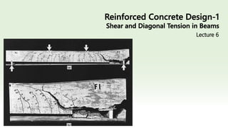
5. Introduction
5
With no shear
reinforcement provided,
the member failed
immediately upon
formation of the critical
crack in the high-shear
region near the right
support.
Shear failure of reinforced
concrete beam: (a) overall
view and (b) detail near
right
support.
6. Diagonal tension in homogeneous elastic beams
• In homogeneous beams, when the material is elastic (stresses
proportional to strains), the bending stresses are equal to
• and the shear stresses are equal to
6
10. Diagonal tension in homogeneous elastic beams
10
• Fig (a) shows a simply supported beam under uniform load. If a
small square element located at the neutral axis of such a beam is
isolated, as shown in Fig. (b), the vertical shear stresses on it, equal
and opposite on the two faces for reasons of equilibrium, act as
shown.
• However, if these were the only stresses present, the element
would not be in equilibrium; it would spin.
• Therefore, on the two horizontal faces there exist equilibrating
horizontal shear stresses of the same magnitude.
11. Diagonal tension in homogeneous elastic beams
11
• If an element of the beam is considered that is located neither at
the neutral axis nor at the outer edges, its vertical faces are
subject not only to the shear stresses but also to the familiar
bending stresses, as shown in Fig. (c).
• Since the magnitudes of the shear stresses and the bending
stresses change both along the beam and vertically with distance
from the neutral axis, the inclinations as well as the magnitudes of
the resulting principal stresses t also vary from one place to
another, as shown in next figure
12. Diagonal tension in homogeneous elastic beams
12
• Figure (f) shows the inclinations of these principal stresses for a
rectangular beam uniformly loaded. That is, these stress
trajectories are lines which, at any point, are drawn in that
direction in which the particular principal stress, tension or
compression, acts at that point.
• It is seen that at the neutral axis the principal stresses in a beam
are always inclined at 45° to the axis. In the vicinity of the outer
fibers they are horizontal near midspan.
13. Diagonal tension in homogeneous elastic beams
13
• An important point follows from this discussion. Tensile stresses,
which are of particular concern in view of the low tensile strength
of the concrete, are not confined to the horizontal bending
stresses f that are caused by bending alone.
• Tensile stresses of various inclinations and magnitudes, resulting
from shear alone (at the neutral axis) or from the combined action
of shear and bending, exist in all parts of a beam and can impair
its integrity if not adequately provided for.
• It is for this reason that the inclined tensile stresses, known as
diagonal tension, must be carefully considered in reinforced
concrete design.
14. Reinforced concrete beams without shear reinforcement
14
• The above discussion of shear in a homogeneous elastic beam
applies very closely to a plain concrete beam without
reinforcement.
• As the load is increased in such a beam, a tension crack will form
where the tensile stresses are largest and will immediately cause
the beam to fail.
• Generally, the largest tensile stresses are those caused at the outer
fiber by bending alone, at the section of maximum bending
moment. In this case, shear has little, if any, influence on the
strength of a beam.
16. Reinforced concrete beams without shear reinforcement
16
• However, when tension reinforcement is provided, the situation is
quite different. Even though tension cracks form in the concrete,
the required flexural tension strength is furnished by the steel, and
much higher loads can be carried.
• Shear stresses increase proportionally to the loads. In
consequence, diagonal tension stresses of significant intensity are
created in regions of high shear forces, chiefly close to the
supports.
17. Reinforced concrete beams without shear reinforcement
17
• The longitudinal tension reinforcement has been so calculated and
placed that it is chiefly effective in resisting longitudinal tension
near the tension face.
• It does not reinforce the tensionally weak concrete against the
diagonal tension stresses that occur elsewhere, caused by shear
alone or by the combined effect of shear and flexure.
• Eventually, these stresses attain magnitudes sufficient to open
additional tension cracks in a direction perpendicular to the local
tension stress. These are known as diagonal cracks, in distinction
to the vertical flexural cracks.
18. Reinforced concrete beams without shear reinforcement
18
• The vertical flexural cracks occur in regions of large moments,
whereas the diagonal cracks occur in regions in which the shear
forces are high.
• In beams in which no reinforcement is provided to counteract the
formation of large diagonal tension cracks, their appearance has
far-reaching and detrimental effects.
21. Formation of Diagonal Cracks
21
• Depending on configuration, support conditions, and load
distribution, a given location in a beam may have a large moment
combined with a small shear force, or the reverse, or large or small
values for both shear and moment.
• Evidently, the relative values of M and V will affect the magnitude
as well as the direction of the diagonal tension stresses.
22. Formation of Diagonal Cracks
22
• If flexural stresses are negligibly small at the particular location,
the diagonal tensile stresses, are inclined at about 45° and are
numerically equal to the shear stresses, with a maximum at the
neutral axis.
• Consequently, diagonal cracks form mostly at or near the neutral
axis and propagate from that location and are also called as also
called as web-shear cracks.
• Web-shear cracking is relatively rare and occurs chiefly near
supports of deep, thin-webbed beams
24. Formation of Diagonal Cracks
24
• The situation is different when both the shear force and the
bending moment have large values.
• At such locations, in a well-proportioned and reinforced beam,
flexural tension cracks form first. Their width and length are well
controlled and kept small by the presence of longitudinal
reinforcement.
• However, when the diagonal tension stress at the upper end of
one or more of these cracks exceeds the tensile strength of the
concrete, the crack bends in a diagonal direction and continues to
grow in length and width.
• These cracks are known as flexure-shear cracks and are more
common than web-shear cracks.
26. Types of Cracks in Reinforced Concrete Beam
1. Flexural Cracks
2. Diagonal Tension Cracks
i. Web-shear cracks: These cracks are formed at locations where flexural
stresses are negligibly small.
ii. Flexure shear cracks: These cracks are formed where shear force and
bending moment have large values.
26
27. Shear and cracks in beams
• It is concluded that the shearing force acting on a vertical section
in a reinforced concrete beam does not cause direct rupture of
that section.
• Shear by itself or in combination with flexure may cause failure
indirectly by producing tensile stresses on inclined planes.
• If these stresses exceed the relatively low tensile strength of
concrete, diagonal cracks develop.
• If these cracks are not checked, splitting of the beam or what is
known as diagonal tension failure will take place.
27
28. Shear Strength of Concrete in Presence of Cracks
• A large number of tests on beams have shown that in regions
where small moment and large shear exist (web shear crack
location) the nominal or average shear strength is taken as
• However in the presence of large moments (for which adequate
longitudinal reinforcement has been provided), the nominal shear
strength corresponding to formation of diagonal tension cracks
can be taken as:
28
𝑉
𝑐𝑟 = 3.5 𝑓𝑐
′
𝑉
𝑐𝑟 = 2 𝑓𝑐
′
29. • The same has been adopted by ACI code (refer to ACI 22.5.2.1).
• This reduction of shear strength of concrete is due to the pre-
existence of flexural cracks.
• It is important to mention here that this value of shear strength of
concrete exists at the ultimate i.e., just prior to the failure
condition.
29
32. ACI Shear Design
32
Stirrups for shear design
𝐴𝑣
𝑓𝑣 𝑜𝑟 𝑓𝑦𝑡 ACI code recommends to use 60000 psi or lower
#3
#4
≤ #10 𝑓𝑙𝑒𝑥𝑢𝑟𝑎𝑙 𝑏𝑎𝑟𝑠
> #10 𝑓𝑙𝑒𝑥𝑢𝑟𝑎𝑙 𝑏𝑎𝑟𝑠
Common
practice
𝑑
45𝑜
𝑑
33. Location of Critical Section for Shear Design
• In most of the cases, for the design of shear, critical shear is taken
at a distance 𝑑 from the support instead of maximum shear at the
face of the support
33
34. Location of Critical Section for Shear Design
34
Typical support
conditions
Typical support
conditions
Concentrated
load within
distance “𝑑”
A beam loaded
near its bottom
edge, e.g.
inverted T-beam
End of a
monolithic vertical
element
Fig a and b are the
more frequent
conditions while the
fig c, d and e are the
special conditions
40. Types of Shear Reinforcement
• The code allows the use of three types of Shear Reinforcement
• Vertical Stirrups
• Inclined stirrups
• Bent up bars
40
Vertical Stirrups
Inclined Stirrups
Bent up bars
Stirrups should be
inclined but practically it
is not feasible
41. Types of Shear Reinforcement
41
Bent up bars
SFD
BMD
𝑉
𝑀 𝑀𝑚𝑎𝑥
42. ACI Code Provisions for Shear Design
• Critical section is at a distance "𝑑“ from the face of support
a. Shear capacity of concrete 𝑉
𝑐
42
𝑉
𝑢 ≤ 𝜙𝑉
𝑛 𝜙 = 0.75 𝑉
𝑛 = (𝑉
𝑐 + 𝑉
𝑠)
Shear strength of cross-section
Total Factored shear force applied at a section
𝑉
𝑢 =
𝑉
𝑛 =
𝑉
𝑐 = 2 𝑓𝑐
′
𝑏𝑤𝑑 𝐸𝑞. 3
43. ACI Code Provisions for Shear Design
b. Minimum shear reinforcement
1. When
2. When
43
𝑉
𝑢 ≤
𝜙𝑉
𝑐
2
𝜙𝑉
𝑐
2
< 𝑉
𝑢 ≤ 𝜙𝑉
𝑐
theoretically no web reinforcement is required.
However ACI 22.5 recommends that minimum
web reinforcement in the form of Maximum
spacing 𝑠𝑚𝑎𝑥 shall be provided where:
no web reinforcement is required
𝑠𝑚𝑎𝑥 𝑠ℎ𝑜𝑢𝑙𝑑 𝑏𝑒 𝑚𝑖𝑛𝑖𝑚𝑢𝑚 𝑜𝑓
൘
𝐴𝑣 𝑓𝑦𝑡
50 𝑏𝑤
ൗ
𝑑
2
24 𝑖𝑛𝑐ℎ𝑒𝑠
൘
𝐴𝑣 𝑓𝑦𝑡
0.75 𝑓𝑐
′
𝑏𝑤
44. ACI Code Provisions for Shear Design
b. Minimum shear reinforcement
3. When
Required Spacing,
If 𝑠𝑑 > 𝑠𝑚𝑎𝑥; use 𝑠𝑚𝑎𝑥
44
𝜙𝑉
𝑐 < 𝑉
𝑢 web reinforcement is required:
𝑠𝑑 =
𝜙𝐴𝑣 𝑓𝑦𝑡 𝑑
𝑉
𝑢 − 𝜙𝑉
𝑐
𝐸𝑞. 8
𝑠𝑚𝑎𝑥 𝑠ℎ𝑜𝑢𝑙𝑑 𝑏𝑒 𝑚𝑖𝑛𝑖𝑚𝑢𝑚 𝑜𝑓
൘
𝐴𝑣 𝑓𝑦𝑡
50 𝑏𝑤
ൗ
𝑑
2
24 𝑖𝑛𝑐ℎ𝑒𝑠
൘
𝐴𝑣 𝑓𝑦𝑡
0.75 𝑓𝑐
′
𝑏𝑤
45. ACI Code Provisions for Shear Design
c. Check for Spacing and Cross-section Depth:
1. If
2. If
3. If
45
𝑉
𝑠 ≤ 2𝑉
𝑐 𝑠𝑚𝑎𝑥 will be as given above (lowest of the 4
options)
2𝑉
𝑐 < 𝑉
𝑠 ≤ 4𝑉
𝑐 Divide 𝑠𝑚𝑎𝑥 by 2
𝑉
𝑠 > 4𝑉
𝑐
Not allowed. Redesign the section
Increase the depth of beam or
increase 𝑓𝑐
′
Depth of beam is ok up to this point
𝑉
𝑐 = 2 𝑓𝑐
′
𝑏𝑤𝑑
46. Placement of Shear Reinforcement
46
𝑉
Support Mid span
𝑉
𝑢
𝜙𝑉
𝑐
𝜙𝑉
𝑐
2
𝑑 𝑠𝑑 𝑠𝑚𝑎𝑥 Theoretically no
stirrups needed
1st stirrup is
provided at s/2
from the face of
the support
When 𝜙𝑉
𝑐<𝑉
𝑢, use Design Spacing, ′𝑠𝑑′
When 𝜙𝑉
𝑐>𝑉
𝑢, use Maximum Spacing, ′𝑠𝑚𝑎𝑥′
𝑉
𝑢 is the shear force at distance “𝑑” from the face of the support.
𝜙𝑉
𝑐 and
𝜙𝑉𝑐
2
are plotted on shear force diagram.
47. Example 6.1
• Beam without web reinforcement.
• A rectangular beam is to be designed to carry a shear force 𝑉
𝑢 of
27 kips. No web reinforcement is to be used, and 𝑓𝑐
′ is 4000 psi.
What is the minimum cross section if controlled by shear?
47
48. Example 6.1
• Solution
• If no web reinforcement is to be used, the cross-sectional
dimensions must be selected so that the applied shear 𝑉
𝑢 is no
larger than one-half the design shear strength (
𝜙𝑉𝑐
2
)
48
𝑉
𝑢 =
𝜙𝑉
𝑐
2
As 𝑉
𝑐 = 2 𝑓𝑐
′
𝑏𝑤𝑑 𝑉
𝑢 =
1
2
𝜙 2 𝑓𝑐
′
𝑏𝑤𝑑
27000 =
1
2
× 0.75 × 2 × 4000 × 𝑏𝑤𝑑
49. Example 6.1
49
27000 =
1
2
× 0.75 × 2 × 4000 × 𝑏𝑤𝑑
𝑏𝑤𝑑 =
27000 × 2
0.75 × 2 × 4000
= 569 𝑖𝑛2
Let 𝑏𝑤 = 18"
then, 𝑑 = 32"
Alternately, if the minimum amount of web reinforcement is used,
the concrete shear resistance may be taken at its full value 𝜙𝑉
𝑐,
50. Example 6.1
50
𝑉
𝑢 = 𝜙𝑉
𝑐
𝑉
𝑢 = 𝜙2 𝑓𝑐
′
𝑏𝑤𝑑
27000 = 0.75 × 2 × 4000 × 𝑏𝑤𝑑
𝑏𝑤𝑑 =
27000
0.75 × 2 × 4000
= 284.6 𝑖𝑛2
Let 𝑏𝑤 = 12"
then, 𝑑 = 24"
Lets say you have to specify the web-reinforcement
52. Example 6.1
52
𝑠𝑚𝑎𝑥 𝑠ℎ𝑜𝑢𝑙𝑑 𝑏𝑒 𝑚𝑖𝑛𝑖𝑚𝑢𝑚 𝑜𝑓
൘
𝐴𝑣 𝑓𝑦𝑡
50 𝑏𝑤
= 22"
ൗ
𝑑
2 = 12"
24 𝑖𝑛𝑐ℎ𝑒𝑠
൘
𝐴𝑣 𝑓𝑦𝑡
0.75 𝑓𝑐
′
𝑏𝑤
= 23.2"
Assuming 𝑓𝑦𝑡 = 60000𝑝𝑠𝑖 and using 2 legs of #3 stirrups
Provide #3 bars @ 12” c/c
53. Example 6.2
• Limits of web reinforcement.
• A simply supported rectangular beam 16 in. wide having an
effective depth of 22 in. carries a total factored load of 9.4 kips/ft
on a 20 ft clear span. It is reinforced with 7.62 in2 of tensile steel,
which continues uninterrupted into the supports. If fc’ = 4000 psi,
throughout what part of the beam is web reinforcement required?
53
55. Example 6.2
• Determine if shear reinforcement is required or not.
If
If
If
55
Step-2
𝑉
𝑢 ≤
𝜙𝑉
𝑐
2
no web reinforcement is required
𝜙𝑉
𝑐
2
< 𝑉
𝑢 ≤ 𝜙𝑉
𝑐
minimum web reinforcement is required
𝜙𝑉
𝑐 < 𝑉
𝑢 web reinforcement is required:
𝑉
𝑢 = 76.8 𝑘 𝜙𝑉
𝑐 = 33.39 𝑘𝑖𝑝𝑠
𝜙𝑉
𝑐
2
= 16.70 𝑘𝑖𝑝𝑠
57. Placement of Shear Reinforcement
57
𝑉
Support Mid span
𝑉
𝑢
𝜙𝑉
𝑐
𝜙𝑉
𝑐
2
𝑑 𝑠𝑑 𝑠𝑚𝑎𝑥 Theoretically no
stirrups needed
1st stirrup is
provided at s/2
from the face of
the support
When 𝜙𝑉
𝑐<𝑉
𝑢, use Design Spacing, ′𝑠𝑑′
When 𝜙𝑉
𝑐>𝑉
𝑢, use Maximum Spacing, ′𝑠𝑚𝑎𝑥′
𝑉
𝑢 is the shear force at distance “𝑑” from the face of the support.
𝜙𝑉
𝑐 and
𝜙𝑉𝑐
2
are plotted on shear force diagram.
60. ACI Code Provisions for Shear Design
c. Check for Spacing and Cross-section Depth:
1. If
2. If
3. If
60
𝑉
𝑠 ≤ 2𝑉
𝑐 𝑠𝑚𝑎𝑥 will be as given above (lowest of the 4
options)
2𝑉
𝑐 < 𝑉
𝑠 ≤ 4𝑉
𝑐 Divide 𝑠𝑚𝑎𝑥 by 2
𝑉
𝑠 > 4𝑉
𝑐
Not allowed. Redesign the section
Increase the depth of beam or
increase 𝑓𝑐
′
Depth of beam is ok up to this point
𝑉
𝑐 = 2 𝑓𝑐
′
𝑏𝑤𝑑
61. Example 6.2
61
𝑉
𝑠 = 57.9𝑘 𝑉
𝑐 = 44.5𝑘
𝑉
𝑠 ≤ 2𝑉
𝑐
57.9 ≤ 2 44.5 𝑂𝑘
As , therefore 𝑠𝑚𝑎𝑥 will not divided by 2
𝑉
𝑠 < 2𝑉
𝑐
As , therefore section is adequate
𝑉
𝑠 < 4𝑉
𝑐
62. • Spacing at critical section
62
𝑠𝑑 =
𝜙𝐴𝑣 𝑓𝑦𝑡 𝑑
𝑉
𝑢 − 𝜙𝑉
𝑐
=
0.75 × 0.22 × 60000 × 22
(76.8 − 33.39) × 1000
𝑠𝑑 = 5"
This is neither so small that placement problems would result nor so large that
maximum spacing criteria would control, and the choice of No. 3 stirrups is
confirmed.
Now 1ST stirrup is provided @ 𝑠𝑑 /2 = 5”/2 = 2.5” = 2” (Rounding) from the
face of the support.
Step-6 Calculate 𝑠𝑑
63. 63
Step-7 Provide reinforcement
𝐷𝑖𝑠𝑡𝑎𝑛𝑐𝑒 𝑓𝑟𝑜𝑚 𝑠𝑢𝑝𝑝𝑜𝑟𝑡 (𝒙) 𝜙𝑉
𝑠 = 9.4 10 − 𝑥 − 33.4
𝑠 =
𝜙𝐴𝑣 𝑓𝑦𝑡 𝑑
𝜙𝑉
𝒔
1.83’ 43.4 k 5”
3’ 32.4 k 6.7”
4’ 23.0 k 9.4”
5’ 13.6 k 16”
𝜙𝑉
𝑠 = 𝑉
𝑢 − 𝜙𝑉
𝑐
𝑉
𝑢 = 9.4 10 − 𝑥
> 𝑠𝑚𝑎𝑥(11")
We cannot use more than 𝑠𝑚𝑎𝑥
Alternatively, we can find the
value of 𝑉
𝑢 after which we can
provide 𝑠𝑚𝑎𝑥
𝑠𝑚𝑎𝑥 =
𝜙𝐴𝑣 𝑓𝑦𝑡 𝑑
𝜙𝑉
𝒔
𝜙𝑉
𝒔 =
𝜙𝐴𝑣 𝑓𝑦𝑡 𝑑
𝑠𝑚𝑎𝑥
=
0.75 × 0.22 × 60 × 22
11
= 19.8 𝑘
𝜙𝑉
𝒔 =
𝜙𝐴𝑣 𝑓𝑦𝑡 𝑑
𝑠𝑚𝑎𝑥
=
0.75 × 0.22 × 60 × 22
11
= 19.8 𝑘
𝜙𝑉
𝒔 = 𝑉
𝑢 − 𝜙𝑉
𝑐 19.8 = 𝑉
𝑢 − 33.4 𝑉
𝑢 = 53.2 𝑘
After this value of 𝑉
𝑢 we can provide 𝑠𝑚𝑎𝑥 (11”), so now we need to find the location of this 𝑉
𝑢
65. • Now 1st stirrup is provided @ 𝑠𝑑 /2 = 5”/2 = 2.5” = 2” (Rounding)
from the face of the support.
• Then 7 stirrups @ 5” = 35”.
• Distance covered by stirrups is = (2”+35”)/12 = 3.1’
• Shear 𝑉
𝑢 at 3.1’ from the support is ;
•
94
10
=
𝑉𝑢
6.9
So Vu = 64.86 k
65
Vu=64.86k
3.1’ 6.9’
94k
Choice 1
66. Example 6.2
• Now here s =
𝜙𝐴𝑣 𝑓𝑦𝑡 𝑑
𝑉𝑢−𝜙𝑉𝑐
=
0.75×0.22×60×22
64.86−33.4
• s = 6.92” ~ 6”
• 3 stirrups @ 6” (It will cover 18”)
• Now total distance covered by stirrups from the face of the
support is:
• Distance =
(2+35+18)"
12
= 4.58’
• Remaining distance is 10’-4.58’ = 5.42’
66
67. Example 6.2
• We will subtract x1 distance from remaining distance, as there is no
need of stirrups in that.
• So 5.42 - x1 = 5.42- 1.78 = 3.64’
• Now no. of stirrups in 3.64’ are:
3.64 ×12
11
= 3.97 (11” is 𝑠𝑚𝑎𝑥)
• 4 stirrups @ 11” will cover 44”.
67
68. Example 6.2
• Total distance in which stirrups are provided is:
•
(2+35+18+44)"
12
= 8.25’
• 10’ – 8.25’ = 1.75’ < x1 (1.78’)
• So we are on safe side.
68
70. Example 6.2
• 1 space at 2 in = 2”
• 7 spaces at 5” = 35”
• 3 spaces at 6” = 18”
• 4 spaces at 11” = 44”
99” = 8 ft 3 inches
70
71. • Now 1st stirrup is provided @ 𝑠𝑑 /2 = 5”/2 = 2.5” = 2” (Rounding)
from the face of the support.
• Distance up to which stirrups need to be provided = 8.22’
• Using 5” spacing
8.22 × 12
5
= 19.7
• Use 19 spaces @ 5”
71
Choice 2
72. Example 6.2
• 1 space at 2 in = 2”
• 19 spaces at 5” = 95”
97” = 8 ft 1 inches
72
73. • Now 1st stirrup is provided @ 𝑠𝑑 /2 = 5”/2 = 2.5” = 2” (Rounding)
from the face of the support.
• Distance up to which stirrups need to be provided = 8.22’=99”
• Distance after which maximum spacing can be provided = 4.34’=52”
• 1 space at 2 in = 2”
• 52”-2” = 50”
• 10 spaces at 5” = 50”
• For rest use 𝑠𝑚𝑎𝑥 = 11“
• 99”-50-2=47”
• 47/11 = 4.27
• So 4 spaces @11”
73
Choice 3
74. Example 6.2
• 1 space at 2 in = 2”
• 5 spaces at 10 in = 50”
• 4 spaces at 11” = 44”
96” = 8 ft
74
75. Example 6.2
• Although not required by the ACI Code, it is good design practice
to continue the stirrups (at maximum spacing) through the middle
region of the beam, even though the calculated shear is low.
• Doing so satisfies the dual purposes of providing continuing
support for the top longitudinal reinforcement that is required
wherever stirrups are used and providing additional shear capacity
in the region to handle load cases not considered in developing
the shear diagram.
75
76. Example 6.3
• Flexural and Shear Design of Beam as per ACI
• Design the beam shown below as per ACI 318-14.
• 𝑓𝑐
′ = 3𝑘𝑠𝑖
• 𝑓𝑦 = 40𝑘𝑠𝑖
76
77. • Minimum depth of beams as per ACI 9.3.1
• Where 𝑙 is the span length of the beam
• For 𝑓𝑦 other than 60 ksi, the expressions in Table shall be multiplied by 0.4 +
𝑓𝑦
100,000
77
Step-1 Selection of sizes of beam
(𝑓𝑦 = 60,000)
78. • For 20′ length, ℎ𝑚𝑖𝑛 = Τ
𝑙
16 = Τ
20×12
16 = 15"
• For grade 40, we have ℎ𝑚𝑖𝑛 = 15 × 0.4 +
𝑓𝑦
100,000
= 12"
• This is the minimum requirement of the code for depth of beam.
• However, we select 18″ deep beam.
• Generally the minimum beam width is 12″, therefore, width of the
beam is taken as 12″
• The final selection of beam size depends on several factors
specifically the availability of formwork.
78
Step-1 Selection of sizes of beam
79. • Depth of beam, ℎ = 18"
• 𝑑 = 18 − 2.5 = 15.5"
• Width of beam cross section 𝑏𝑤 = 12"
79
Step-1 Selection of sizes of beam
83. Second trial
Assuming 𝑎 = 3.82“
So 𝐴𝑠 = 2.90 𝑖𝑛2 is ok
Provide 4#8 bars (3.16 in2)
(Check from Annex whether we can provide these bars in 1 layer or not)
83
Step-4 Design
=
1422
0.9 × 40 × 15.5 −
3.82
2
= 2.90 𝑖𝑛2
Check 𝑎
= 3.79 𝑖𝑛2
84. • Check for 𝐴𝑠,𝑚𝑖𝑛 and 𝐴𝑠,𝑚𝑎𝑥 or
• Check for 𝜌𝑚𝑖𝑛 and 𝜌𝑚𝑎𝑥
• 𝜌𝑎𝑐𝑡𝑢𝑎𝑙 =
𝐴𝑠
𝑏𝑤𝑑
=
3.16
12×15.5
= 0.0169
• 𝜌𝑚𝑖𝑛 = 0.005
• 𝜌max(0.004) = 0.0232
• 𝜌(0.005) = 0.0203
𝜌𝑚𝑖𝑛 < 𝜌𝑎𝑐𝑡𝑢𝑎𝑙 < 𝜌max(0.004) Ok
• Also, 𝜌𝑎𝑐𝑡𝑢𝑎𝑙 < 𝜌(0.005), therefore 𝜙 = 0.9 Ok
84
Step-4 Design
Table A.4
87. 87
Step-4 Design
• Design for Shear:
• Other Checks
• 2𝑉
𝑐 = 2 × 2 𝑓𝑐
′
𝑏𝑤𝑑 = 4 × 3000 × 12 × 15.5/1000 = 40.7𝑘
• 𝑉
𝑠 = 𝑉
𝑢 − 𝜙𝑉
𝑐 = 20.64 − 15.28 = 5.36 k
• Also
𝑉
𝑠 ≤ 2𝑉
𝑐 𝑠𝑚𝑎𝑥 will not be halved
𝑉
𝑠 ≤ 4𝑉
𝑐
Depth of beam is ok, if not then increase 𝑑
88. 88
Step-5 Drafting (shear reinforcement)
3.22’
6.45’
3.55’
6.78’
As 𝑠𝑑 > 𝑠𝑚𝑎𝑥, we will provide 𝑠𝑚𝑎𝑥 from the support up to 6.78 ft. Beyond
this point, theoretically no reinforcement is required, however, we will
provide #3 2-legged stirrups @ 12 in c/c.
89. 89
Step-5 Drafting (shear reinforcement)
• 1 space at s/2 in = 3.8”
• 10 spaces at 7.75” = 77.5”
• 3 spaces at 12” = 36”
117.3”
= 9 ft 9 inches