LECTURE OUTLINE
1. Capacitorsand Capacitance
2. Geometry Effects On Capacitance
3. Arrangement of Capacitors
4. Potential Energy of Capacitance (Energy Stored)
5. Capacitor with dielectric
3.
SR
1. CAPACITORS AND
CAPACITANCE
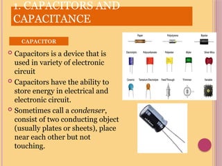
Capacitors is a device that is
used in variety of electronic
circuit
Capacitors have the ability to
store energy in electrical and
electronic circuit.
Sometimes call a condenser,
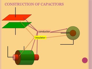
consist of two conducting object
(usually plates or sheets), place
near each other but not
touching.
CAPACITOR
4.
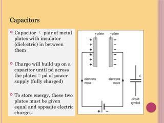
Capacitor pair of metal
plates with insulator
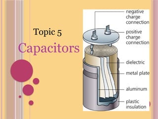
(dielectric) in between
them
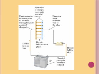
Charge will build up on a
capacitor until pd across
the plates = pd of power
supply (fully charged)
To store energy, these two
plates must be given
equal and opposite electric
charges.
Capacitors
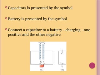
Capacitors ispresented by the symbol
Battery is presented by the symbol
Connect a capacitor to a battery –charging –one
positive and the other negative
7.
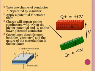
Take twochunks of conductor
Separated by insulator
Apply a potential V between
them
Charge will appear on the
conductors, with +Q on the
higher-potential and -Q on the
lower potential conductor
Capacitance depends upon
both the “geometry” and the
nature of the material that is
the insulator 0
V
Q+ = +CV
+++++++++++
+++++++++++
+++++++++++
-----------
-----------
----------
Q- = -CV
V
8.
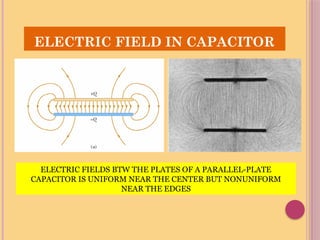
ELECTRIC FIELD INCAPACITOR
ELECTRIC FIELDS BTW THE PLATES OF A PARALLEL-PLATE
CAPACITOR IS UNIFORM NEAR THE CENTER BUT NONUNIFORM
NEAR THE EDGES
10.
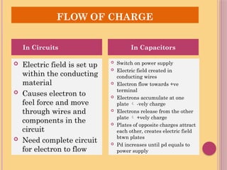
FLOW OF CHARGE
Electric field is set up
within the conducting
material
Causes electron to
feel force and move
through wires and
components in the
circuit
Need complete circuit
for electron to flow
Switch on power supply
Electric field created in
conducting wires
Electron flow towards +ve
terminal
Electrons accumulate at one
plate -vely charge
Electrons release from the other
plate +vely charge
Plates of opposite charges attract
each other, creates electric field
btwn plates
Pd increases until pd equals to
power supply
In Circuits In Capacitors
11.
CAPACITANCE
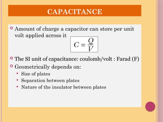
Amount ofcharge a capacitor can store per unit
volt applied across it
The SI unit of capacitance: coulomb/volt : Farad (F)
Geometrically depends on:
Size of plates
Separation between plates
Nature of the insulator between plates
SR
2.GEOMETRY EFFECTS ON
CAPACITANCE
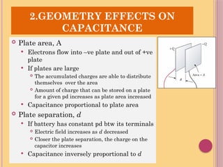
Plate area, A
Electrons flow into –ve plate and out of +ve
plate
If plates are large
The accumulated charges are able to distribute
themselves over the area
Amount of charge that can be stored on a plate
for a given pd increases as plate area increased
Capacitance proportional to plate area
Plate separation, d
If battery has constant pd btw its terminals
Electric field increases as d decreased
Closer the plate separation, the charge on the
capacitor increases
Capacitance inversely proportional to d
15.
GEOMETRY EFFECTS ON
CAPACITANCE
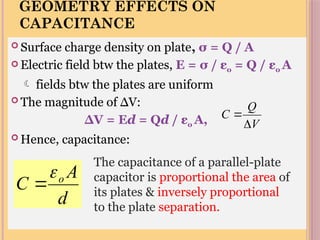
Surface charge density on plate, σ = Q / A
Electric field btw the plates, E = σ / εo = Q / εo A
fields btw the plates are uniform
The magnitude of ∆V:
∆V = Ed = Qd / εo A,
Hence, capacitance:
d
A
C o
The capacitance of a parallel-plate
capacitor is proportional the area of
its plates & inversely proportional
to the plate separation.
V
Q
C
16.
Determination of Capacitance
Relation between Q and ΔV, and from it we can
get the capacitance C in term of geometry of the
plate
Area is large – more charge can be held each plate
Distance is large – further apart, less attractive
force on the other plate, drawn less charge from
battery
d
A
V
Q
C 0
17.
WHAT IS “ƐO”??
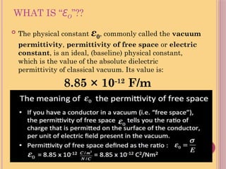
The physical constant ε0, commonly called the vacuum
permittivity, permittivity of free space or electric
constant, is an ideal, (baseline) physical constant,
which is the value of the absolute dielectric
permittivity of classical vacuum. Its value is:
8.85 × 10⁻¹²
F/m
18.
Example of capacitancecalculation:
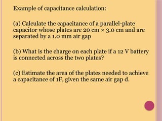
(a) Calculate the capacitance of a parallel-plate
capacitor whose plates are 20 cm × 3.0 cm and are
separated by a 1.0 mm air gap
(b) What is the charge on each plate if a 12 V battery
is connected across the two plates?
(c) Estimate the area of the plates needed to achieve
a capacitance of 1F, given the same air gap d.
19.
Example of capacitancecalculation:
Solution
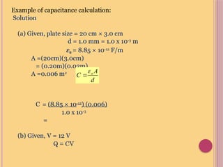
(a) Given, plate size = 20 cm × 3.0 cm
d = 1.0 mm = 1.0 x 10⁻³
m
ε0 = 8.85 × 10⁻¹²
F/m
A =(20cm)(3.0cm)
= (0.20m)(0.03m)
A =0.006 m2
C = (8.85 × 10⁻¹²
) (0.006)
1.0 x 10-3
=
(b) Given, V = 12 V
Q = CV
d
A
C o
20.
Example of capacitancecalculation:
Solution
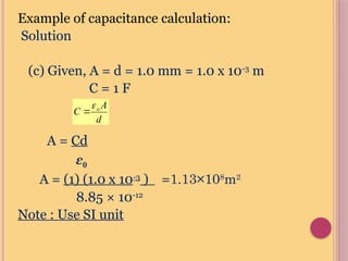
(c) Given, A = d = 1.0 mm = 1.0 x 10⁻³
m
C = 1 F
A = Cd
ε0
A = (1) (1.0 x 10⁻³
) =1.13×10⁸
m2
8.85 × 10⁻¹²
Note : Use SI unit
d
A
C o
21.
3. ARRANGEMENT OF
CAPACITORS
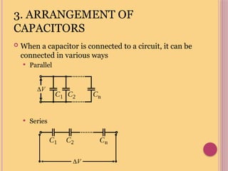
When a capacitor is connected to a circuit, it can be
connected in various ways
Parallel
Series
V
V
22.
SR
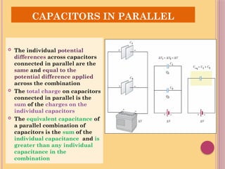
CAPACITORS IN PARALLEL
The individual potential
differences across capacitors
connected in parallel are the
same and equal to the
potential difference applied
across the combination
The total charge on capacitors
connected in parallel is the
sum of the charges on the
individual capacitors
The equivalent capacitance of
a parallel combination of
capacitors is the sum of the
individual capacitance and is
greater than any individual
capacitance in the
combination
23.
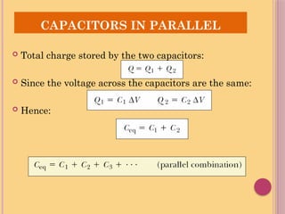
CAPACITORS IN PARALLEL
Total charge stored by the two capacitors:
Since the voltage across the capacitors are the same:
Hence:
24.
SR
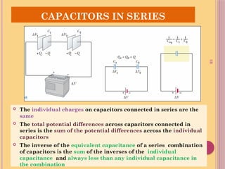
CAPACITORS IN SERIES
The individual charges on capacitors connected in series are the
same
The total potential differences across capacitors connected in
series is the sum of the potential differences across the individual
capacitors
The inverse of the equivalent capacitance of a series combination
of capacitors is the sum of the inverses of the individual
capacitance and always less than any individual capacitance in
the combination
25.
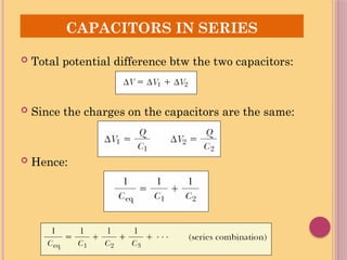
CAPACITORS IN SERIES
Total potential difference btw the two capacitors:
Since the charges on the capacitors are the same:
Hence:
26.
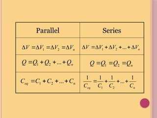
Parallel Series
n
V
V
V
V
2
1
n
Q
Q
Q
Q
...
2
1
n
eq C
C
C
C
...
2
1
n
V
V
V
V
...
2
1
n
Q
Q
Q
Q
2
1
n
eq C
C
C
C
1
...
1
1
1
2
1
27.
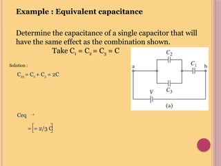
Example : Equivalentcapacitance
Determine the capacitance of a single capacitor that will
have the same effect as the combination shown.
Take C1 = C2 = C3 = C
Solution :
C23 = C2 + C3 = 2C
Ceq -1
= = 2/3 C
28.
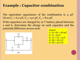
Example : Capacitorcombination
The equivalent capacitance of the combination is 4 μF.
Given C1 = 6.0 μF, C2 = 4.0 μF, C3 = 8.0 μF.
If the capacitors are charged by 12 V battery placed between
a and b, determine the charge on each capacitor and the
potential difference across each.
Answer:
1) QT =Q1 = 48.0µC
2) V1 = 8.0V
3) V2 = V3 = 4.0V
4) Q2 = 16.0 µC
5) Q3 = 32.0 µC
29.
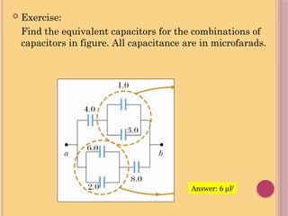
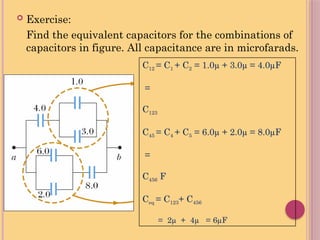
Exercise:
Find theequivalent capacitors for the combinations of
capacitors in figure. All capacitance are in microfarads.
Answer: 6 μF
30.
Exercise:
Find theequivalent capacitors for the combinations of
capacitors in figure. All capacitance are in microfarads.
C12 = C1 + C2 = 1.0µ + 3.0µ = 4.0µF
=
C123
C45 = C4 + C5 = 6.0µ + 2.0µ = 8.0µF
=
C456 F
Ceq = C123+ C456
= 2µ + 4µ = 6µF
31.
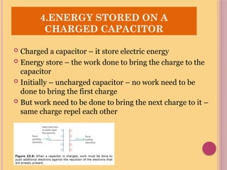
Charged acapacitor – it store electric energy
Energy store – the work done to bring the charge to the
capacitor
Initially – uncharged capacitor – no work need to be
done to bring the first charge
But work need to be done to bring the next charge to it –
same charge repel each other
4.ENERGY STORED ON A
CHARGED CAPACITOR
32.
CHARGING AND DISCHARGING
CAPASITOR
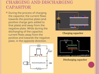
During the process of charging
the capacitor, the current flows
towards the positive plate (and
positive charge gets added to
that plate) and away from the
negative plate. While during the
discharging of the capacitor,
current flows away from the
positive and towards the negative
plate, in the opposite direction.
Discharging capacitor
Charging capacitor
33.
4.ENERGY STORED ONA
CHARGED CAPACITOR
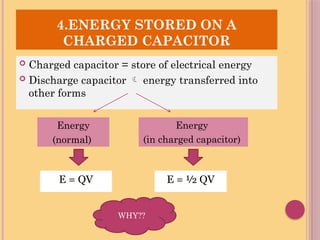
Charged capacitor = store of electrical energy
Discharge capacitor energy transferred into
other forms
Energy
(normal)
Energy
(in charged capacitor)
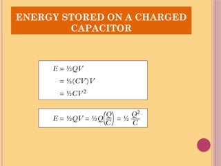
E = QV E = ½ QV
WHY??
34.
SR
ENERGY STORED ONA CHARGED
CAPACITOR
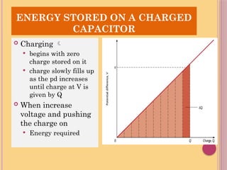
Charging
begins with zero
charge stored on it
charge slowly fills up
as the pd increases
until charge at V is
given by Q
When increase
voltage and pushing
the charge on
Energy required
Example: Energy storedin a capacitor
1) A camera flash unit stores energy in a 150 μF capacitor
at 200 V. How much electric energy can be stored?
2) A capacitor 6.0μF is connected to another capacitor
10μF in series. Each capacitor stored 40μC of charge.
Calculate the energy store on each capacitor.
37.
Energy Stored inA Capacitor
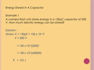
Example 1
A camera flash unit stores energy in a 150μC capacitor at 200
V. How much electric energy can be stored?
Solution :
Given: C = 150μF = 150 x 10-6
F
V = 200 V
= 150 x 10-6
)(200)2
= 150 x 10-6
)(40000)
E = 3.0 J
38.
Energy Stored inA Capacitor
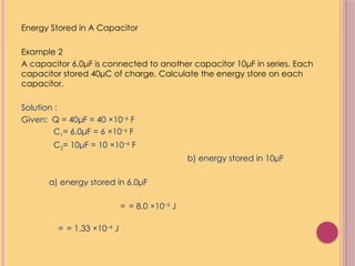
Example 2
A capacitor 6.0μF is connected to another capacitor 10μF in series. Each
capacitor stored 40μC of charge. Calculate the energy store on each
capacitor.
Solution :
Given: Q = 40μF = 40 ×10−6
F
C1= 6.0μF = 6 ×10⁻⁶
F
C2= 10μF = 10 ×10−6
F
b) energy stored in 10μF
a) energy stored in 6.0μF
= = 8.0 ×10⁻⁵
J
= = 1.33 ×10⁻⁴
J
39.
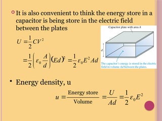
It isalso convenient to think the energy store in a
capacitor is being store in the electric field
between the plates
SR
2
2
1
CV
U
Ad
E
Ed
d
A 2
0
2
0
2
1
2
1
• Energy density, u
2
0
2
1
E
Ad
U
Energy store
Volume
u
40.
o A dielectricis an insulating material that, when placed
between the plates of a capacitor, increases the
capacitance
o Dielectrics include rubber, plastic, or waxed paper
o Use of dielectric
o Prevent break down – more voltage can be apply
o Plate can be place much closer without touching – increase capacitance with
less d
o Increase the capacitance by the factor of K (dielectric constant)
5. CAPACITOR WITH DIELECTRIC
41.
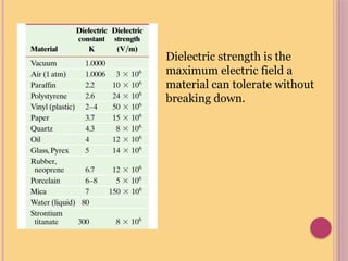
Dielectric strength isthe
maximum electric field a
material can tolerate without
breaking down.
42.
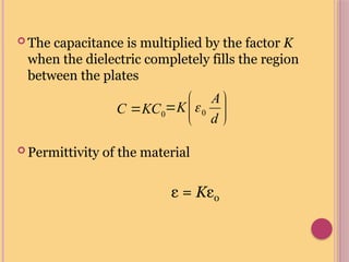
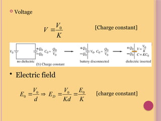
The capacitanceis multiplied by the factor K
when the dielectric completely fills the region
between the plates
Permittivity of the material
ε = Kε0
0
KC
C
d
A
K 0
43.
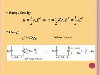
Energy density
Charge
[Voltage Constant]
0
KQ
Q
2
2
0
2
0
2
1
2
1
2
1
E
E
K
u
E
u
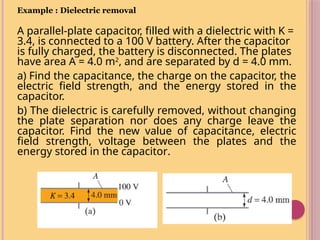
Example : Dielectricremoval
A parallel-plate capacitor, filled with a dielectric with K =
3.4, is connected to a 100 V battery. After the capacitor
is fully charged, the battery is disconnected. The plates
have area A = 4.0 m2
, and are separated by d = 4.0 mm.
a) Find the capacitance, the charge on the capacitor, the
electric field strength, and the energy stored in the
capacitor.
b) The dielectric is carefully removed, without changing
the plate separation nor does any charge leave the
capacitor. Find the new value of capacitance, electric
field strength, voltage between the plates and the
energy stored in the capacitor.