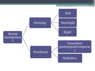
IDEAL STUMP CONCEPT
•Ideal length and shape
• Bone end well covered with muscles
• Non adherent incision scar
• Good muscle power
• Absence of neuroma
• Free from infection
• Full and free movements at the joint above
• No fixed deformity
7.
SKIN FLAPS
• Thickflaps
• Normal sensation
• Incisions along limb axis
• Flexion creases : oblique/transverse incisions to
avoid flexion contractures
• Subcutaneous fat excised 2-3 cm from wound
edges
8.
MUSCLE
• Muscles dividedabout 5 cm distal to intended
bone section
• Muscle viability : contractility
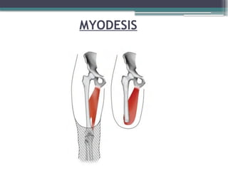
• Muscle stabilization : Myodesis, Myoplasty
• Muscle activity : improves circulation and hence,
healing potential
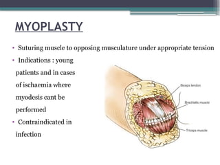
MYOPLASTY
• Suturing muscleto opposing musculature under appropriate tension
• Indications : young
patients and in cases
of ischaemia where
myodesis cant be
performed
• Contraindicated in
infection
11.
BLOOD VESSELS
• Ligationof arteries and veins separately
• Double ligation of large vessels
• Minor vessels cauterized
12.
NERVES
• Isolated, pulledgently distally and divided so that
cut end retracts proximal to level of bone resection
• Strong tension and crushing : neuroma, phantom
pain
• Large nerves like Sciatic nerve ligated before
division
13.
BONE
• Level ofcut : delicate balance between healing
potential and functionality
• Excessive periosteal stripping avoided
• Bony prominences resected and rasped until smooth
contour achieved
• Cut should be such that there will be good soft tissue
coverage and suture line wont be in tension
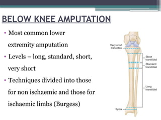
BELOW KNEE AMPUTATION
•Most common lower
extremity amputation
• Levels – long, standard, short,
very short
• Techniques divided into those
for non ischaemic and those for
ischaemic limbs (Burgess)
16.
NON ISCHAEMIC LIMBS
•Tourniquet
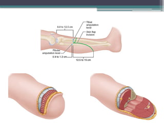
• Ideal stump length : 12.5-17.5 cm from tibial
tuberosity
• 2.5 cm stump length for each 30 cm of body height
• If < 12.5 cm – less efficient functionally
• Tension myodesis
18.
ISCHAEMIC LIMBS
• Higherlevel : 10 to 12.5 cm distal to joint line
• Tension myodesis contraindicated
• Tourniquet avoided
• Long posterior flap : 1 cm longer than AP diameter of
leg at level of bone section
• Short anterior flap : just distal to level of bone
section
20.
ABOVE KNEE AMPUTATION
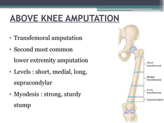
•Transfemoral amputation
• Second most common
lower extremity amputation
• Levels : short, medial, long,
supracondylar
• Myodesis : strong, sturdy
stump
21.
AMPUTATIONS OF UPPEREXTREMITY
• 20 times less common than amputations of lower
extremity
• Most common cause : trauma
• Shoulder disarticulation, forequarter amputation :
malignancy
• Length preservation : function of prosthesis
decreases with higher levels of amputation
22.
AMPUTATION IN CHILDREN
•Length preservation
• Growth plate preservation
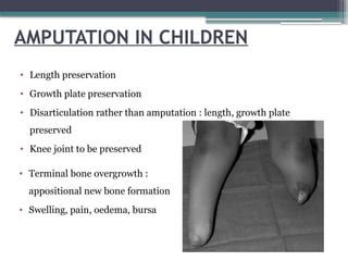
• Disarticulation rather than amputation : length, growth plate
preserved
• Knee joint to be preserved
• Terminal bone overgrowth :
appositional new bone formation
• Swelling, pain, oedema, bursa
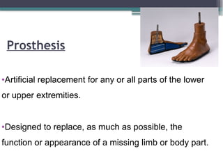
Prosthesis
•Artificial replacement forany or all parts of the lower
or upper extremities.
•Designed to replace, as much as possible, the
function or appearance of a missing limb or body part.
25.
Aim of prosthesis
To substitute for a lost part
To restore lost function.
Comfortable ambulation
Minimal/reduce of expenditure of energy
Minimizing the shift of the center of gravity of the body
during gait
26.
Preparatory (Temporary) Prosthesis
•Made prior to definitive prosthesis. It helps in shrinking and
shaping of the residual limb.
• Allows early prosthetic training (gait and functional training)
and fine tuning of the prosthetic alignment as the amputee’s
gait progress
• Used for 3 to 6 months of post surgery (until maximal stump
shrinkage has been achieved).
27.
Definitive (Permanent) Prosthesis:
•Once residual limb volume has stabilized, a definitive
or permanent prosthesis is made.
• Applied after 3-9 months postoperative.
• Life span of 3-5 years.
• Changes are needed when there is residual limb atrophy,
weight gain or loss and excessive wear.
28.
Components
• Socket (withor without a socket liner)
• Suspension system
• Interposed joint components
• Shank(pylon)
• Prosthetic foot
29.
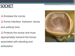
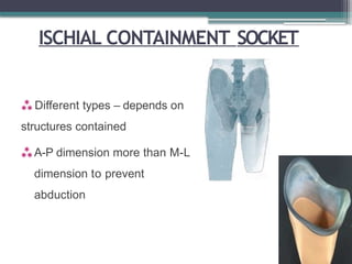
SOCKET
Encloses thestump
Forms interface between stump
and artificial limb.
Protects the stump and must
appropriately transmit the forces
associated with standing and
ambulation
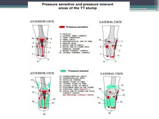
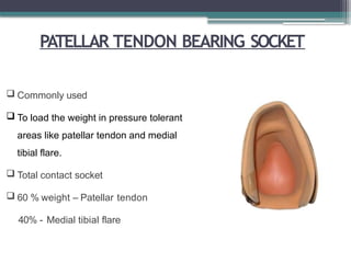
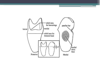
PATELLAR TENDON BEARINGSOCKET
Commonly used
To load the weight in pressure tolerant
areas like patellar tendon and medial
tibial flare.
Total contact socket
60 % weight – Patellar tendon
40% - Medial tibial flare
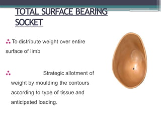
TOTAL SURFACE BEARING
SOCKET
To distribute weight over entire
surface of limb
Strategic allotment of
weight by moulding the contours
according to type of tissue and
anticipated loading.
37.
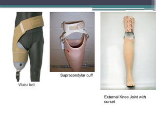
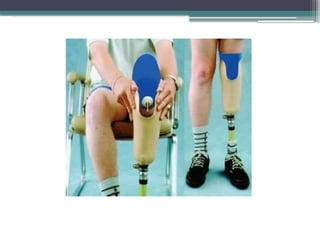
SUSPENSION
Prevent theprosthesis from falling off the residual
limb.
Types -
Straps
Sleeves
Gel liners with locking mechanisms
Suction
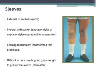
Sleeves
• External tosocket (sleeve)
• Integral with socket (supracondylar or
supracondylar-suprapatellar suspension)
• Locking mechanism incorporated into
prosthesis.
• Difficult to don- needs good grip strength
to pull up the sleeve ,Dermatitis
40.
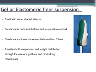
Gel or Elastomericliner suspension
• Prosthetic sock- shaped sleeves.
• Functions as both an interface and suspension method
• Creates a suction environment between limb & liner
• Provides both suspension and weight distribution
through the use of a gel liner and pin-locking
mechanism
42.
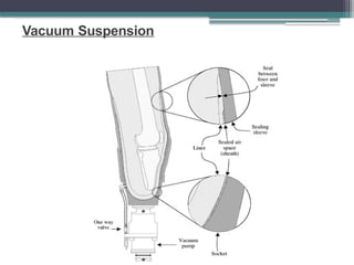
Suction Suspension
• Oneway expulsion valve placed in distal socket.
• Allows air to escape from socket.
• Air tight closure.
• Partial vacuum is created in the socket by pistoning action of
residual limb within socket
43.
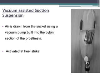
Vacuum assisted Suction
Suspension
•Air is drawn from the socket using a
vacuum pump built into the pylon
section of the prosthesis.
• Activated at heel strike
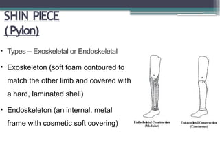
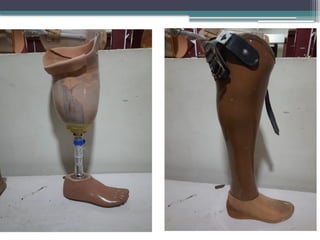
SHIN PIECE
(Pylon)
• Types– Exoskeletal or Endoskeletal
• Exoskeleton (soft foam contoured to
match the other limb and covered with
a hard, laminated shell)
• Endoskeleton (an internal, metal
frame with cosmetic soft covering)
47.
KNEE JOINT PROSTHESIS
Mustfulfill the following 3 functions:
• Provide support during the stance phase of
ambulation
• Produce smooth control during the swing phase
• Maintain unrestricted motion for sitting and kneeling
48.
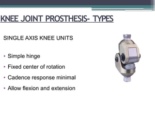
KNEE JOINT PROSTHESIS-TYPES
SINGLE AXIS KNEE UNITS
• Simple hinge
• Fixed center of rotation
• Cadence response minimal
• Allow flexion and extension
49.
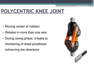
POLYCENTRIC KNEE JOINT
•Moving center of rotation
• Rotates in more than one axis
• During swing phase, it leads to
shortening of distal prosthesis
enhancing toe clearance
50.
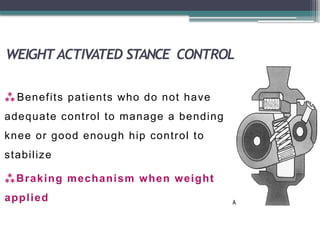
WEIGHTACTIVATED STANCE CONTROL
Benefits patients who do not have
adequate control to manage a bending
knee or good enough hip control to
stabilize
Braking mechanism when weight
applied
51.
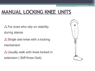
MANUAL LOCKING KNEEUNITS
For ones who rely on stability
during stance
Single axis knee with a locking
mechanism
Usually walk with knee locked in
extension ( Stiff Knee Gait)
52.
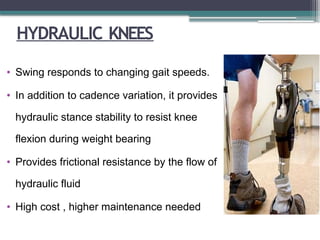
HYDRAULIC KNEES
• Swingresponds to changing gait speeds.
• In addition to cadence variation, it provides
hydraulic stance stability to resist knee
flexion during weight bearing
• Provides frictional resistance by the flow of
hydraulic fluid
• High cost , higher maintenance needed
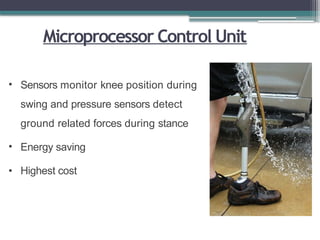
Microprocessor Control Unit
•Sensors monitor knee position during
swing and pressure sensors detect
ground related forces during stance
• Energy saving
• Highest cost
55.
Prosthetic foot
The 5basic functions of the prosthetic foot are as follows:
• Provide a stable, weight-bearing surface
• Absorb shock
• Replace lost muscle function
• Replicate the anatomic joint
• Restore cosmetic appearance
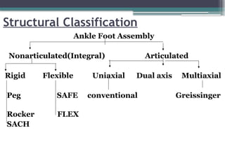
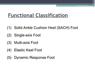
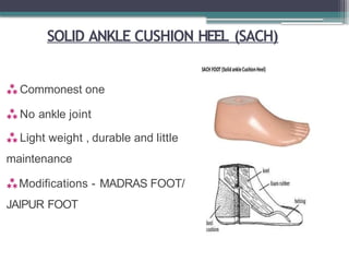
SOLID ANKLE CUSHIONHEEL (SACH)
Commonest one
No ankle joint
Light weight , durable and little
maintenance
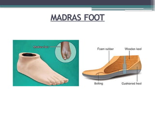
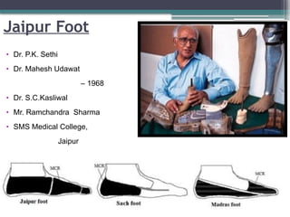
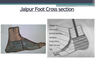
Modifications - MADRAS FOOT/
JAIPUR FOOT
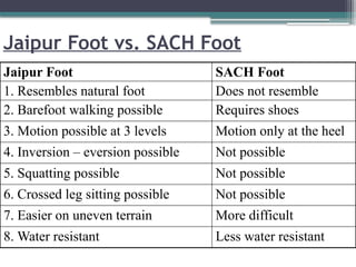
Jaipur Foot vs.SACH Foot
Jaipur Foot SACH Foot
1. Resembles natural foot Does not resemble
2. Barefoot walking possible Requires shoes
3. Motion possible at 3 levels Motion only at the heel
4. Inversion – eversion possible Not possible
5. Squatting possible Not possible
6. Crossed leg sitting possible Not possible
7. Easier on uneven terrain More difficult
8. Water resistant Less water resistant
63.
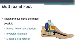
Multi axial Foot
•Triplanar movements are made
possible
▫ Plantar flexion-dorsiflexion
▫ Inversion-eversion
▫ Medial-lateral rotation
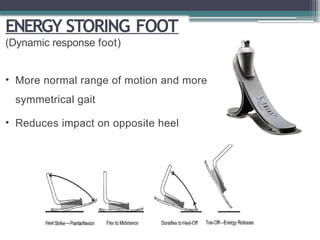
ENERGY STORING FOOT
(Dynamicresponse foot)
• More normal range of motion and more
symmetrical gait
• Reduces impact on opposite heel
66.
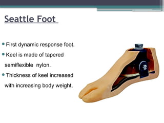
Seattle Foot
First dynamicresponse foot.
Keel is made of tapered
semiflexible nylon.
Thickness of keel increased
with increasing body weight.
67.
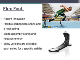
Flex Foot
• RecentInnovation
• Flexible carbon fibre shank and
a heel spring
• Entire assembly stores and
releases energy
• Many versions are available,
each suited for a specific activity
68.
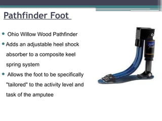
Pathfinder Foot
OhioWillow Wood Pathfinder
Adds an adjustable heel shock
absorber to a composite keel
spring system
Allows the foot to be specifically
"tailored" to the activity level and
task of the amputee
69.
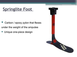
Carbon /epoxy pylon that flexes
under the weight of the amputee
Unique one-piece design
Springlite Foot
70.
COMPLICATIONS
Choke syndrome
Caused byobstructed venous outflow due
to a socket that is too snug.
• Acute phase - Red indurated skin with
orange-peel appearance
• Chronic phase - hemosiderin deposits
and venous stasis ulcers
71.
Painful residual limb
Possiblecauses include bony prominences, poorly fitting
prosthesis, neuroma formation and insufficient soft tissue
coverage
Skin problems
• Contact dermatitis
most commonly caused by liner, socks, and suspension
mechanism
Treatment-
remove the offending item ,symptomatic treatment
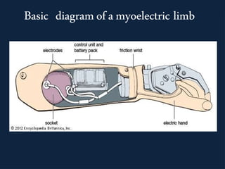
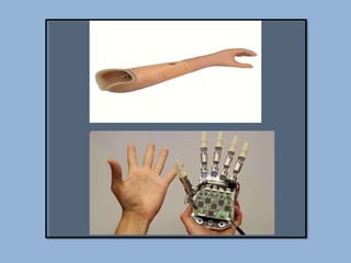
Components of a
myoelectricprosthesis:
The limb consists of
a) A set of electrodes
b)A circuitry that consists of operational amplifiers,
filters ,comparators, battery and feedback
systems
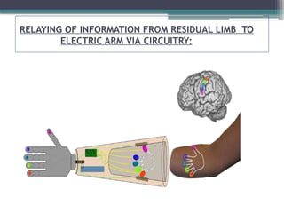
c) A relay system between the circuitry and the robotic
arm
77.
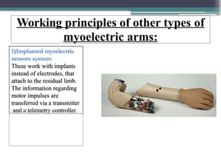
Working principles ofother types of
myoelectric arms:
1)Implanted myoelectric
sensors system:
These work with implants
instead of electrodes, that
attach to the residual limb.
The information regarding
motor impulses are
transferred via a transmitter
and a telemetry controller.
78.
Working principles ofother types of myoelectric
arms(cont..)
2)Real-time myoelectric control of a multi-fingered hand
prosthesis using
•PCA (Principle Component Analysis)
•The controller here reverts the PCA algorithm and
allows to drive a multi- DoF hand by combining two-
differential channels EMG input.
79.
Working principles ofother types of myoelectric
arms(cont..)
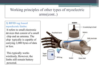
3) RFID tag based
myoelectric limbs:
It refers to small electronic
devices that consist of a small
chip and an antenna. The
chip typically is capable of
carrying 2,000 bytes of data
or less.
This typically works
wirelessly, However, the
limbs still remain battery
powered.
80.
Applications & Advantages
Movementsinclude:
•Elbow flexion/extension
•Forearm supination/pronation
•Opening/closing of fingers
•Quick reflexes
•Secure hold
•Grasping objects
•Comes in different sizes
81.
Disadvantages:
1) Motor anddrive last about two to three years.
2)When used on a child, the sockets need to be
replaced every year due to growth.
3)The material used in making it may result in skin
irritations, inflammations, infections in the initial
days.
4) Relatively expensive.
#7 Dog ears and redundant skin avoided
Adherence of scar to bone avoided
#8 Retracts proximally after division
Continue to contract : dynamic stump
#9 Attachment of sectioned muscles under appropriate tension to bone : stabilization of stump
Suturing muscle to bone
Through pre drilled holes
Contraindicated in ischaemia
#10 Advantages:- 1) Improves the function of the muscles, 2) Increases the circulation of the stump, 3) Prevents phantom pain
#12 Never ligated along with a vessel : leads to unremitting pain
#13 Bone is cut through the prepared level of section.
Some surgeons have advised to close the medullary canal at the end of the bone by osteoperiosteal flap to maintain the normal pressure gradient within the canal. Some have proposed to create a synostosis between the tibia and fibula to prevent the abnormal diversion of these bones during walking so that more stable and non compressible below knee stump is formed.
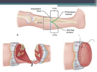
#17 Equal anterior and posterior flaps
Length = half of AP diameter of leg at level of bone section
Incision curved convex distally
Periosteum marked while crossing tibial crest
Reflection of anterior flap as single layer with deep fascia and periosteum till level of intended bone section
Superficial peroneal nerve drawn distally and divided
Anterior compartment muscles divided 0.6 cm distal to bone section level
Anterior tibial vessels, deep peroneal nerve ligated, divided
Transverse sectioning of tibia
Fibula sectioned 1.2 cm proximally
Gastrocnemius-soleus
bevelled to form
myofascial flap
Bone ends rasped,
smoothened
#18 Anterolateral muscles
divided
Anterior tibial vessels and peroneal nerve ligated, divided
Tibia sectioned, fibula sectioned 0.9-1.3 cm proximally
Anterolateral muscles
divided
Anterior tibial vessels and peroneal nerve ligated, divided
Tibia sectioned, fibula sectioned 0.9-1.3 cm proximally
#19 Posterior muscle mass dissected; vessels and nerves ligated, divided
Tibia bevelled on anterior
and medial aspects
Posterior muscle mass
bevelled and tailored
into flap
Sutured to deep fascia
and periosteum anteriorly
Drain placed, skin flaps
sutured
#25 The type of prosthesis is determined by the extent of an amputation
#30 To give weight during stance phase
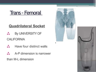
Anterior wall contoured to direct force posteriorly to triangle –to keep ischium in position
Flat posterior Ischial seat – major weight bearing area
#31 CAT – CAM- contoured adducted trochanteric controlled alignment method- to maintain femur in adducted position and to control socket rotation by containing ischial tuberocity
#34 Name – because of the BAR that is built in to patella tendon , patella and tibial tubercle
#35 Socket aligned at 5° of knee flexion.
Lateral and posterior brim –
level of adducter tubercle.
Posterior brim – proximal to patella bar - provide stability, prevent the limb from sliding too far to socket
#38 Old age obese short stump unstable knee.. Disadv quadrieps wasting
#41 The pin is attached to the distal end of the liner.
The locking mechanism is attached to the distal socket.
#45 Substitute for the human leg
Transmit body weight from the socket of the prosthesis to the foot.
#47 The prosthetic knee can have a single axis with a simple hinge and a single pivot point, or it may have a polycentric axis with multiple centers of rotation
#48 No mechanical stability
Give support during stance not during swing
Light weight , durable and low maintanace
Not good for ones having short stump
For patients with primary residual limb who can voluntary stabilize the knee through active hip extension against posterior wall of prosthesis
#49 Good for long residual limb or knee disarticulation patients
Good stance phase stability – so in short stump ones and hip extensor weakness patients
Less durable than single axis
#50 To prevent unwanted knee flexion while standing
If initial contact made when knee not completely extended (in uneven surface) provides additional stability and prevent buckling
#51 Locks when knee fully extended
Compromise toe clearance in swing
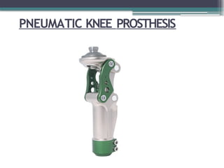
#53 LIKE HYDRAULIC
Less weight , maintainance cost less
Less cadence control than hydraulic
#58 Rigid keel made of wood or metal
Cushion heel – rubber heel or alternating hard and soft rubber layers
Cushion heel compresses during heel strike –stimulate plantar flexion
#59 Modification of SACH
Space between heel and ground filled with sponge rubber
Toes shaped like normal
Tendo achilles like shape made
Rubber sole for bare foot walking
#61 3 structural blocks simulating the anatomy of normal foot.
Forefoot and heel blocks -sponge rubber
Ankle block –light wood.
Cosmetic appearance of a real foot
#63 High performance – preferred by dancers, golfers and the like
High initial cost and cost of maintenance
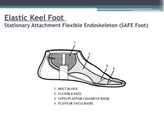
#64 Developed in 1970s.
Elastic keel replaced the rigid keel used in the SACH
Uses a series of Dacron bands and polyurethane structures
Mimics the "windlass" action of the human foot during push-off
#65 Absorb energy on heel contact
Release in terminal stance providing propulsion
More normal range of motion and more symmetrical gait
Reduces impact on opposite heel
#66 the Seattle Foot(tm) is designed to store and release energy, which it accomplishes with a specially designed keel that compresses during foot flat and extends during toe off. The keel aids the patient by thrusting the prosthesis forward, simulating the natural push-off provided by the gastrocnemius and soleus muscles.
#68 Similar in concept to the Flex-
Foot Reflex VSP
#69 (the heel spring is fused to the pylon spring with a compressible urethane elastomer heel web)
#78 Hence, the novelty of this approach stood in the PCA application for solving the challenging problem of best mapping the EMG inputs into the degrees of freedom (DoFs) of the prosthesis.
#80 Other advantages:
Can be given to a child at the age of 18-24 months.
Comes with a one or two year guarantee
Flexible in functioning
No need to learn functioning and handling of the arm
#81 With heavy use, the entire prosthesis may need to be replaced after only four or five years.
 Most read