Prepared by
Mr P.M.Subramanian, Guest Lecturer, FTS Department
UNIT 3 FIRE PREVENTION AND PROTECTION
Fire Source : Sources of ignition – fire triangle – principles of fire extinguishing – active and
passive fire protection systems – various classes of fires – A, B, C, D, E.Protection : Types of
fire extinguishers – fire stoppers – hydrant pipes – hoses –monitors – fire watchers – layout of
stand pipes – fire station- fire alarms and sirens – maintenance of fire trucks – foam generators –
Escape from fire rescue operations –fire drills – notice-first aid for burns.
1
Fire Source :
Sources of ignition
In Fire Engineering, a source of ignition provides the minimum thermal energy required to raise
the temperature of a combustible fuel-air mixture to its ignition point, initiating self-sustaining
combustion.
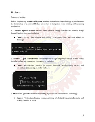
1. Electrical Ignition Sources Occurs when electrical energy converts into thermal energy
through faults or improper insulation.
●​ Causes: Arcing, short circuits, overloading, loose connections, and static electricity
discharge.
2. Thermal / Open Flame Sources Direct exposure to high-temperature objects or bare flames
transferring heat via conduction, convection, or radiation.
●​ Causes: Naked flames (matches, gas burners), hot work (welding/cutting torches), and
hot surfaces (exhaust pipes, boiler walls).
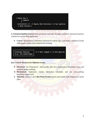
3. Mechanical Ignition Sources Generated by physical work converted into heat energy.
●​ Causes: Friction (unlubricated bearings, slipping V-belts) and impact sparks (metal tool
striking concrete or steel).
2
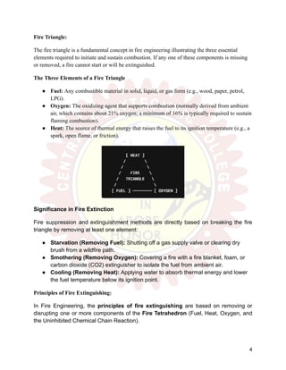
4. Chemical Ignition Sources Heat generated internally through exothermic chemical reactions
without an external heat application.
●​ Causes: Spontaneous combustion (linseed-oil-soaked rags, coal heaps), reaction of acids
with organic matter, and oxidation heat buildup.
Key Control Measures for Diploma Exams
●​ Electrical: Use Flameproof / Intrinsically Safe (Ex) equipment in hazardous zones and
maintain proper earthing.
●​ Mechanical: Implement routine lubrication schedules and use non-sparking
beryllium-copper tools.
●​ Thermal: Enforce a strict Hot Work Permit system and insulate high-temperature steam
pipes.
3
Fire Triangle:
The fire triangle is a fundamental concept in fire engineering illustrating the three essential
elements required to initiate and sustain combustion. If any one of these components is missing
or removed, a fire cannot start or will be extinguished.
The Three Elements of a Fire Triangle
●​ Fuel: Any combustible material in solid, liquid, or gas form (e.g., wood, paper, petrol,
LPG).
●​ Oxygen: The oxidizing agent that supports combustion (normally derived from ambient
air, which contains about 21% oxygen; a minimum of 16% is typically required to sustain
flaming combustion).
●​ Heat: The source of thermal energy that raises the fuel to its ignition temperature (e.g., a
spark, open flame, or friction).
Significance in Fire Extinction
Fire suppression and extinguishment methods are directly based on breaking the fire
triangle by removing at least one element:
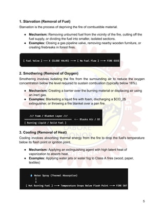
●​ Starvation (Removing Fuel): Shutting off a gas supply valve or clearing dry
brush from a wildfire path.
●​ Smothering (Removing Oxygen): Covering a fire with a fire blanket, foam, or
carbon dioxide (CO2) extinguisher to isolate the fuel from ambient air.
●​ Cooling (Removing Heat): Applying water to absorb thermal energy and lower
the fuel temperature below its ignition point.
Principles of Fire Extinguishing:
In Fire Engineering, the principles of fire extinguishing are based on removing or
disrupting one or more components of the Fire Tetrahedron (Fuel, Heat, Oxygen, and
the Uninhibited Chemical Chain Reaction).
4
1. Starvation (Removal of Fuel)
Starvation is the process of depriving the fire of combustible material.
●​ Mechanism: Removing unburned fuel from the vicinity of the fire, cutting off the
fuel supply, or dividing the fuel into smaller, isolated sections.
●​ Examples: Closing a gas pipeline valve, removing nearby wooden furniture, or
creating firebreaks in forest fires.
2. Smothering (Removal of Oxygen)
Smothering involves isolating the fire from the surrounding air to reduce the oxygen
concentration below the level required to sustain combustion (typically below 16%).
●​ Mechanism: Creating a barrier over the burning material or displacing air using
an inert gas.
●​ Examples: Blanketing a liquid fire with foam, discharging a $CO_2$
extinguisher, or throwing a fire blanket over a pan fire.
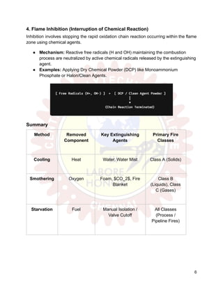
3. Cooling (Removal of Heat)
Cooling involves absorbing thermal energy from the fire to drop the fuel's temperature
below its flash point or ignition point.
●​ Mechanism: Applying an extinguishing agent with high latent heat of
vaporization to absorb heat.
●​ Examples: Applying water jets or water fog to Class A fires (wood, paper,
textiles)
5
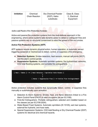
4. Flame Inhibition (Interruption of Chemical Reaction)
Inhibition involves stopping the rapid oxidation chain reaction occurring within the flame
zone using chemical agents.
●​ Mechanism: Reactive free radicals (H and OH) maintaining the combustion
process are neutralized by active chemical radicals released by the extinguishing
agent.
●​ Examples: Applying Dry Chemical Powder (DCP) like Monoammonium
Phosphate or Halon/Clean Agents.
Summary
Method Removed
Component
Key Extinguishing
Agents
Primary Fire
Classes
Cooling Heat Water, Water Mist Class A (Solids)
Smothering Oxygen Foam, $CO_2$, Fire
Blanket
Class B
(Liquids), Class
C (Gases)
Starvation Fuel Manual Isolation /
Valve Cutoff
All Classes
(Process /
Pipeline Fires)
6
Inhibition Chemical
Chain Reaction
Dry Chemical Powder
(DCP), Halon
substitutes
Class B, Class
C, Electrical
Equipment
Active and Passive Fire Protection Systems:
Active and passive fire protection systems form the dual-defense approach in fire
engineering, where active systems take dynamic action to detect or extinguish fires and
passive systems rely on structural containment to slow the spread of fire and smoke.
Active Fire Protection Systems (AFP)
AFP systems require dynamic physical action, human operation, or automatic sensor
triggering (powered or mechanical) to detect, control, or suppress a fire emergency.
●​ Detection Systems: Smoke detectors, heat sensors, manual call points (MCP),
and fire alarm control panels.
●​ Suppression Systems: Automatic sprinkler systems, fire hydrant/riser networks,
CO2 total flooding systems, and portable fire extinguishers.
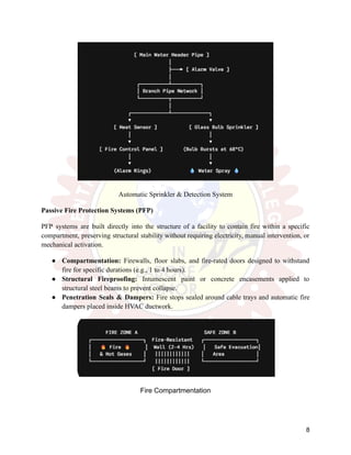
Active protection includes systems that dynamically detect, control, or suppress fires
manually or automatically upon activation.
●​ Detection & Alarm Systems: Smoke, heat, and flame detectors linked to a Fire
Alarm Control Panel (FACP) to alert occupants (as per IS 2189).
●​ First-Aid Extinguishers: Portable extinguishers selected and installed based on
fire classes (as per IS 2190:2024).
●​ Water-Based Fixed Systems: Automatic sprinklers (IS 15105), wet riser systems,
external fire hydrants, and hose reels.
●​ Special Suppression Systems: CO2 total flooding or Dry Chemical Powder (DCP)
systems for electrical and chemical hazards.
7
Automatic Sprinkler & Detection System
Passive Fire Protection Systems (PFP)
PFP systems are built directly into the structure of a facility to contain fire within a specific
compartment, preserving structural stability without requiring electricity, manual intervention, or
mechanical activation.
●​ Compartmentation: Firewalls, floor slabs, and fire-rated doors designed to withstand
fire for specific durations (e.g., 1 to 4 hours).
●​ Structural Fireproofing: Intumescent paint or concrete encasements applied to
structural steel beams to prevent collapse.
●​ Penetration Seals & Dampers: Fire stops sealed around cable trays and automatic fire
dampers placed inside HVAC ductwork.
Fire Compartmentation
8
Passive protection uses structural elements to limit the spread of fire and smoke without
requiring mechanical activation or human intervention.
●​ Firewalls & Compartmentation: Dividing buildings into fire zones using 2–4 hour
fire-resistance-rated masonry or concrete walls.
●​ Fire Doors & Dampers: Fire-rated doors installed along escape routes and
automatic thermal dampers inside air-conditioning (HVAC) ducts to isolate
smoke.
●​ Structural Fireproofing: Encasing structural steel beams in concrete or applying
intumescent paint to prevent structural collapse under high heat.
Comparison
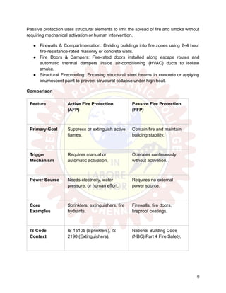
Feature Active Fire Protection
(AFP)
Passive Fire Protection
(PFP)
Primary Goal Suppress or extinguish active
flames.
Contain fire and maintain
building stability.
Trigger
Mechanism
Requires manual or
automatic activation.
Operates continuously
without activation.
Power Source Needs electricity, water
pressure, or human effort.
Requires no external
power source.
Core
Examples
Sprinklers, extinguishers, fire
hydrants.
Firewalls, fire doors,
fireproof coatings.
IS Code
Context
IS 15105 (Sprinklers), IS
2190 (Extinguishers).
National Building Code
(NBC) Part 4 Fire Safety.
9
Various Classes of Fires – A, B, C, D, E.
Fires are categorized into distinct classes based on the type of fuel involved, allowing fire
engineers to select the appropriate extinguishing agent as per Indian Standards (IS 2190) and the
National Building Code (NBC).
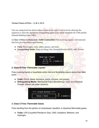
1. Class A Fires: Carbonaceous / Solid Combustibles Fires involving organic solid materials
that form glowing embers upon burning.
●​ Fuels: Wood, paper, cloth, rubber, plastics, and trash.
●​ Extinguishing Media: Water (Cooling), Dry Chemical Powder (DCP), ABC Powder.
2. Class B Fires: Flammable Liquids
Fires involving liquids or liquefiable solids that emit flammable vapors above their flash
point.
●​ Fuels: Petrol, diesel, kerosene, paints, thinners, and grease.
●​ Extinguishing Media: Mechanical Foam (Smothering), CO2, Dry Chemical
Powder. (Never use water streams).
3. Class C Fires: Flammable Gases
Fires resulting from the ignition of compressed, liquefied, or dissolved flammable gases.
●​ Fuels: LPG (Liquefied Petroleum Gas), CNG, Acetylene, Methane, and
Hydrogen.
10
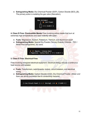
●​ Extinguishing Media: Dry Chemical Powder (DCP), Carbon Dioxide ($CO_2$).
The primary action is isolating the gas valve (Starvation).
4. Class D Fires: Combustible Metals Fires involving active metals that burn at
extremely high temperatures and react violently with water.
●​ Fuels: Magnesium, Sodium, Potassium, Titanium, and Aluminium swarf.
●​ Extinguishing Media: Special Dry Powder (Ternary Eutectic Chloride - TEC /
Metal Fire Extinguisher), dry sand.
5. Class E Fires: Electrical Fires
Fires involving energized electrical equipment. Electrical energy acts as a continuous
heat source until isolated.
●​ Fuels: Transformers, switchboards, motors, circuit breakers, and electrical
wiring.
●​ Extinguishing Media: Carbon Dioxide (CO2), Dry Chemical Powder. (Water and
foam are strictly prohibited due to conductivity hazards).
11
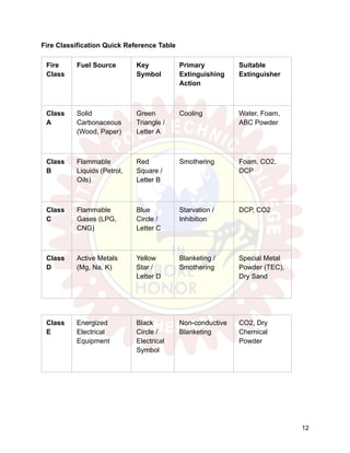
Fire Classification Quick Reference Table
Fire
Class
Fuel Source Key
Symbol
Primary
Extinguishing
Action
Suitable
Extinguisher
Class
A
Solid
Carbonaceous
(Wood, Paper)
Green
Triangle /
Letter A
Cooling Water, Foam,
ABC Powder
Class
B
Flammable
Liquids (Petrol,
Oils)
Red
Square /
Letter B
Smothering Foam, CO2,
DCP
Class
C
Flammable
Gases (LPG,
CNG)
Blue
Circle /
Letter C
Starvation /
Inhibition
DCP, CO2
Class
D
Active Metals
(Mg, Na, K)
Yellow
Star /
Letter D
Blanketing /
Smothering
Special Metal
Powder (TEC),
Dry Sand
Class
E
Energized
Electrical
Equipment
Black
Circle /
Electrical
Symbol
Non-conductive
Blanketing
CO2, Dry
Chemical
Powder
12
Protection:
In Fire Engineering, Fire Protection refers to the design, installation, and application of systems,
structures, and practices aimed at safeguarding life, property, and the environment from fire
hazards.
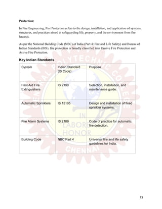
As per the National Building Code (NBC) of India (Part 4: Fire and Life Safety) and Bureau of
Indian Standards (BIS), fire protection is broadly classified into Passive Fire Protection and
Active Fire Protection.
Key Indian Standards
System Indian Standard
(IS Code)
Purpose
First-Aid Fire
Extinguishers
IS 2190 Selection, installation, and
maintenance guide.
Automatic Sprinklers IS 15105 Design and installation of fixed
sprinkler systems.
Fire Alarm Systems IS 2189 Code of practice for automatic
fire detection.
Building Code NBC Part 4 Universal fire and life safety
guidelines for India.
13
Types of fire extinguishers:
In fire engineering, portable fire extinguishers are active fire protection devices classified by
their extinguishing agent and operational mechanism as per Indian Standards (IS 15683 / IS
2190).
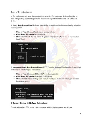
1. Water Type Extinguisher Designed specifically for solid combustible materials by providing
a cooling effect.
●​ Class of Fire: Class A (Wood, paper, textile, rubber).
●​ Color Band (IS Standard): Signal Red.
●​ Mechanism: Cools the fuel below its ignition temperature. (Never use on electrical or
liquid fires).
2. Mechanical Foam Type Extinguisher (AFFF) Contains Aqueous Film Forming Foam mixed
with water to smother liquid surface fires.
●​ Class of Fire: Class A and Class B (Petrol, diesel, paints).
●​ Color Band (IS Standard): Cream / Pale Cream.
●​ Mechanism: Forms a floating foam blanket over liquid fuel to cut off oxygen and trap
flammable vapors.
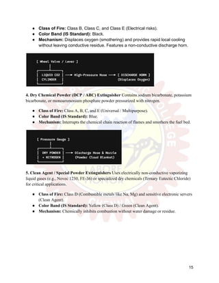
3. Carbon Dioxide (CO2) Type Extinguisher
Contains liquefied CO2 under high pressure, which discharges as a cold gas.
14
●​ Class of Fire: Class B, Class C, and Class E (Electrical risks).
●​ Color Band (IS Standard): Black.
●​ Mechanism: Displaces oxygen (smothering) and provides rapid local cooling
without leaving conductive residue. Features a non-conductive discharge horn.
4. Dry Chemical Powder (DCP / ABC) Extinguisher Contains sodium bicarbonate, potassium
bicarbonate, or monoammonium phosphate powder pressurized with nitrogen.
●​ Class of Fire: Class A, B, C, and E (Universal / Multipurpose).
●​ Color Band (IS Standard): Blue.
●​ Mechanism: Interrupts the chemical chain reaction of flames and smothers the fuel bed.
5. Clean Agent / Special Powder Extinguishers Uses electrically non-conductive vaporizing
liquid gases (e.g., Novec 1230, FE-36) or specialized dry chemicals (Ternary Eutectic Chloride)
for critical applications.
●​ Class of Fire: Class D (Combustible metals like Na, Mg) and sensitive electronic servers
(Clean Agent).
●​ Color Band (IS Standard): Yellow (Class D) / Green (Clean Agent).
●​ Mechanism: Chemically inhibits combustion without water damage or residue.
15
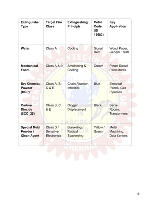
Extinguisher
Type
Target Fire
Class
Extinguishing
Principle
Color
Code
(IS
15683)
Key
Application
Water Class A Cooling Signal
Red
Wood, Paper,
General Trash
Mechanical
Foam
Class A & B Smothering &
Cooling
Cream Petrol, Diesel,
Paint Stores
Dry Chemical
Powder
(DCP)
Class A, B,
C & E
Chain Reaction
Inhibition
Blue Electrical
Panels, Gas
Pipelines
Carbon
Dioxide
($CO_2$)
Class B, C
& E
Oxygen
Displacement
Black Server
Rooms,
Transformers
Special Metal
Powder /
Clean Agent
Class D /
Sensitive
Electronics
Blanketing /
Radical
Scavenging
Yellow /
Green
Metal
Machining,
Data Centers
16
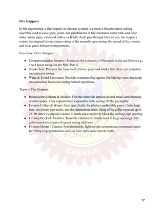
Fire Stoppers:
In fire engineering, a fire stopper (or firestop system) is a passive fire protection sealing
assembly used to close gaps, joints, and penetrations in fire-resistance-rated walls and floor
slabs. When pipes, electrical cables, or HVAC ducts pass through fire barriers, fire stoppers
restore the original fire-resistance rating of the assembly, preventing the spread of fire, smoke,
and toxic gases between compartments.
Functions of Fire Stoppers
●​ Compartmentation Integrity: Maintains the continuity of fire-rated walls and floors (e.g.,
1 to 4 hours rating) as per NBC Part 4.
●​ Smoke Seal: Prevents the movement of toxic gases and smoke into clean exit corridors
and adjacent rooms.
●​ Water & Sound Resistance: Provides waterproofing against firefighting water discharge
and acoustical insulation during normal operations.
Types of Fire Stoppers
●​ Intumescent Sealants & Mastics: Flexible materials applied around small cable bundles
or metal pipes. They expand when exposed to heat, sealing off the gap tightly.
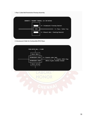
●​ Firestop Collars & Wraps: Used specifically for plastic/combustible pipes. Under high
heat, the plastic pipe melts, and the intumescent inner lining of the collar expands up to
25–50 times its original volume to crush and completely block the melting pipe opening.
●​ Firestop Bricks & Modules: Reusable elastomeric blocks used in large openings (like
cable trays) that require frequent wiring additions.
●​ Firestop Mortar / Cement: Non-shrinkable, light-weight cementitious compounds used
for filling large penetration voids in floor slabs and concrete walls.
17
18
Key Technical Parameters
Parameter Specification / Standard
Primary Standard
(India)
National Building Code (NBC) Part 4 / IS 12458
Testing Standard ASTM E814 / ISO 834 / BS 476 Part 20
Fire Resistance
Ratings
F-Rating (Flame resistance duration) & T-Rating
(Thermal transfer limit)
Expansion Ratio Intumescent materials expand 10x to 50x their original
volume at 180°C–200°C
Hydrant Pipes:
In fire engineering, a hydrant pipe system (also known as a fire riser or fire main system) is an
assembly of heavy-duty piping installed inside and around a facility. It provides a continuous,
high-pressure water supply to landing valves and hose connections, enabling firefighters and
trained personnel to extinguish fires efficiently.
Types of Hydrant Pipe Systems
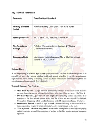
●​ Wet Riser System: A pipe network permanently charged with water under dynamic
pressure from fire pumps. It is used in buildings taller than 15 meters as per NBC Part 4.
●​ Dry Riser System: A pipe network kept empty of water during normal conditions. In an
emergency, the fire brigade pumps water into the system via an external Fire Brigade
Connection (Breeching Inlet). Used in buildings up to 15 meters or unheated structures.
●​ Downcomer System: A vertical pipe network connected directly to an overhead water
tank, pressurized by gravity or an automatic booster pump located on the roof.
●​ Yard Hydrant / External Ring Main: A horizontal underground or aboveground piping
network running around the perimeter of a plant or facility, serving external standpost
hydrants.
19
20
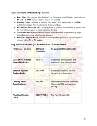
Key Components of Hydrant Pipe Systems
●​ Riser Pipes: Heavy-grade Mild Steel (MS) or Galvanized Iron (GI) pipes conforming to
IS 1239 / IS 3589, painted Fire Red (Shade 536 of IS 5).
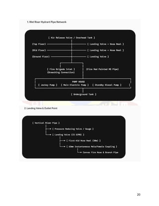
●​ Landing Valves: Gunmetal or stainless steel outlet valves (conforming to IS 5290)
installed at strategic floor locations and staircase landings.
●​ Fire Brigade Breeching Inlet: A 2-way or 4-way collector head installed at ground level
for external fire engines to pump water into the riser.
●​ Air Release Valves: Installed at the highest point of the riser to automatically purge
trapped air, preventing water hammer damage.
●​ Pressure Gauges & PRVs: Installed to ensure working pressure at any landing valve
remains within 3.5 to 7.0 kg/cm².
Key Indian Standards (IS) Reference for Diploma Exams
Parameter / Element Standard /
Guideline
Requirement / Specification
Code of Practice for
Internal Hydrants
IS 3844 Guidelines for installation and
maintenance of internal risers.
External Hydrant
System Code
IS 13039 Selection and layout for yard
hydrants and ring mains.
Landing Valve
Specifications
IS 5290 Standard dimensions, materials
(Gunmetal/SS), and pressure
testing.
Pipe Identification
Color
IS 2379 / IS 5 Fire Red (Shade 536).
21
Standard Landing
Valve Pressure
NBC Part 4 Minimum 3.5 kg/cm^2, Maximum
7.0 kg/cm^2 at the nozzle.
Hoses:
In fire engineering, a fire hose is a flexible, high-pressure conduit used to convey water or
extinguishing agents from a water source (such as a fire engine, pump, or hydrant) to the point of
fire application.
1. Delivery Hoses
Delivery hoses transport pressurized water from a pump or hydrant to the nozzle. They operate
under internal positive pressure.
●​ Percolating Hose: Constructed from unlined natural flax or hemp canvas weave. A small
fraction of water seeps (percolates) through the fabric weave, keeping the outer surface
wet to protect the hose against burning embers.
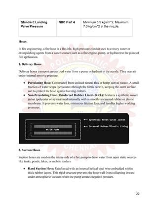
●​ Non-Percolating Hose (Reinforced Rubber Lined - RRL): Features a synthetic woven
jacket (polyester or nylon) lined internally with a smooth vulcanized rubber or plastic
membrane. It prevents water loss, minimizes friction loss, and handles higher working
pressures.
2. Suction Hoses
Suction hoses are used on the intake side of a fire pump to draw water from open static sources
like tanks, ponds, lakes, or mobile tenders.
●​ Hard Suction Hose: Reinforced with an internal helical steel wire embedded within
thick rubber layers. This rigid structure prevents the hose wall from collapsing inward
under atmospheric vacuum when the pump creates negative pressure.
22
●​ Soft Suction Hose: A short length of large-diameter flexible delivery hose used to
connect a pressurized hydrant directly to the pump intake.
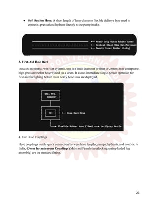
3. First-Aid Hose Reel
Installed in internal wet riser systems, this is a small-diameter (19mm or 25mm), non-collapsible,
high-pressure rubber hose wound on a drum. It allows immediate single-person operation for
first-aid firefighting before main heavy hose lines are deployed.
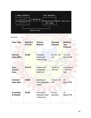
4. Fire Hose Couplings
Hose couplings enable quick connection between hose lengths, pumps, hydrants, and nozzles. In
India, 63mm Instantaneous Couplings (Male and Female interlocking spring-loaded lug
assembly) are the standard fitting.
23
Summary
Hose Type Standard
IS Code
Primary
Material
Standard
Diameter
Working /
Test
Pressure
Delivery
Hose (RRL)
IS 636 Polyester
jacket with
rubber lining
63 mm / 38

mm
14 to 35
$kg/cm^2$
Hard
Suction
Hose
IS 2410 Rubber with
embedded
steel wire
75 mm to
100 mm
Full Vacuum
(~760 mm
Hg)
First-Aid
Hose Reel
IS 884 Reinforced
non-collapsible
rubber
19 mm / 25
mm
10
$kg/cm^2$
Couplings
& Nozzles
IS 903 Gunmetal /
Stainless Steel
/ Aluminium
63 mm
standard
15
$kg/cm^2$
24
Monitors:
In fire engineering, a fire monitor (also called a water/foam cannon) is a heavy-duty,
high-capacity discharge device capable of delivering large volumes of water or foam solution
over long distances. Monitors are deployed where standard hand-held hose lines (which typically
deliver 300–500 LPM) are insufficient to handle large-scale, high-intensity fires.
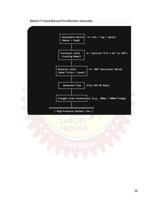
1. Key Functions and Features
●​ High Flow Rates: Delivers flow rates ranging from 1,000 LPM to over 20,000 LPM
(Liters Per Minute).
●​ Extended Reach: Can throw water/foam streams 50 to 100+ meters horizontally and
vertically.
●​ Articulated Movement: Rotates 360° horizontally (azimuth) and tilts vertically
(elevation) from -45° to +85°.
●​ Reaction Force Management: Fixed mounting or heavy bases absorb high thrust reaction
forces, eliminating operator fatigue and reducing personnel hazards.
2. Classification of Fire Monitors
A. Based on Mounting / Portability
1.​ Fixed / Ground-Mounted Monitors: Permanently bolted to concrete foundations or steel
risers in high-risk industrial sites (oil refineries, chemical plants, tank farms).
2.​ Portable / Ground Monitors: Mobile units transported to site and anchored on ground
legs/spikes for temporary high-volume deployment.
3.​ Trailer / Vehicle-Mounted Monitors: Mounted on mobile trailers, fire tenders, or foam
tenders for flexible field positioning.
4.​ Tower / Elevated Monitors: Installed on elevated steel towers (10 to 30 meters high) to
spray directly over bulk fuel storage tanks.
B. Based on Operation
1.​ Manual Monitors: Operated directly by firefighters using handwheels, tiller bars, or
worm-gear hand cranks.
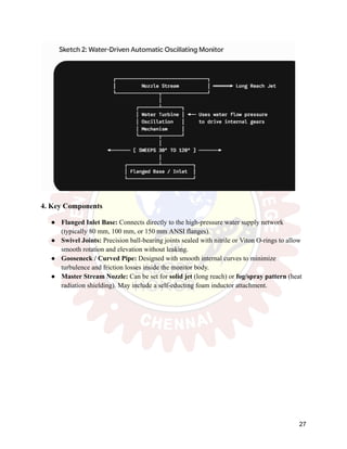
2.​ Remote Controlled / Oscillating Monitors: Driven by electric, hydraulic, or water-turbine
motors, enabling remote control from safe zones or automatic sweeping (oscillating)
patterns.
25
26
4. Key Components
●​ Flanged Inlet Base: Connects directly to the high-pressure water supply network
(typically 80 mm, 100 mm, or 150 mm ANSI flanges).
●​ Swivel Joints: Precision ball-bearing joints sealed with nitrile or Viton O-rings to allow
smooth rotation and elevation without leaking.
●​ Gooseneck / Curved Pipe: Designed with smooth internal curves to minimize
turbulence and friction losses inside the monitor body.
●​ Master Stream Nozzle: Can be set for solid jet (long reach) or fog/spray pattern (heat
radiation shielding). May include a self-educting foam inductor attachment.
27
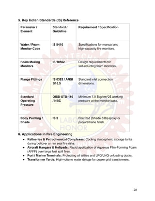
5. Key Indian Standards (IS) Reference
Parameter /
Element
Standard /
Guideline
Requirement / Specification
Water / Foam
Monitor Code
IS 8410 Specifications for manual and
high-capacity fire monitors.
Foam Making
Monitors
IS 10502 Design requirements for
self-educting foam monitors.
Flange Fittings IS 6392 / ANSI
B16.5
Standard inlet connection
dimensions.
Standard
Operating
Pressure
OISD-STD-116
/ NBC
Minimum 7.0 $kg/cm^2$ working
pressure at the monitor base.
Body Painting /
Shade
IS 5 Fire Red (Shade 536) epoxy or
polyurethane finish.
6. Applications in Fire Engineering
●​ Refineries & Petrochemical Complexes: Cooling atmospheric storage tanks
during boilover or rim seal fire risks.
●​ Aircraft Hangars & Helipads: Rapid application of Aqueous Film-Forming Foam
(AFFF) over large fuel spill fires.
●​ Port / Marine Terminals: Protecting oil jetties and LPG/LNG unloading docks.
●​ Transformer Yards: High-volume water deluge for power grid transformers.
28
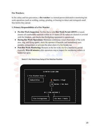
Fire Watchers:
In fire safety and loss prevention, a fire watcher is a trained person dedicated to monitoring hot
work operations (such as welding, cutting, grinding, or brazing) to detect and extinguish small
fires before they spread.
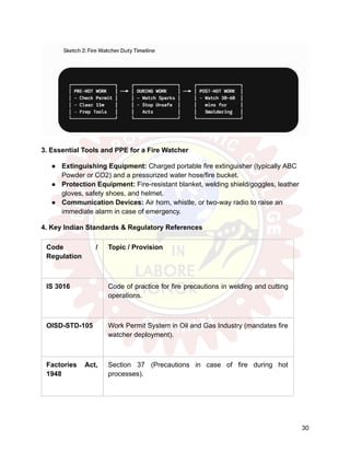
1. Primary Responsibilities of a Fire Watcher
●​ Pre-Hot Work Inspection: Verifies that a valid Hot Work Permit (HWP) is issued,
ensures all combustible materials within an 11-meter (35 ft) radius are cleared or covered
with fire blankets, and checks that firefighting equipment is operational.
●​ During Hot Work Operations: Maintains continuous visual observation of the work
area, slag, and flying sparks; alerts the operator of hazards; and immediately uses
portable extinguishers or activates the plant alarm if a fire breaks out.
●​ Post-Hot Work Monitoring: Remains at the hot work site for a mandatory period
(typically 30 to 60 minutes) after operations stop to inspect for smoldering embers or
hidden hot spots.
29
3. Essential Tools and PPE for a Fire Watcher
●​ Extinguishing Equipment: Charged portable fire extinguisher (typically ABC
Powder or CO2) and a pressurized water hose/fire bucket.
●​ Protection Equipment: Fire-resistant blanket, welding shield/goggles, leather
gloves, safety shoes, and helmet.
●​ Communication Devices: Air horn, whistle, or two-way radio to raise an
immediate alarm in case of emergency.
4. Key Indian Standards & Regulatory References
Code /
Regulation
Topic / Provision
IS 3016 Code of practice for fire precautions in welding and cutting
operations.
OISD-STD-105 Work Permit System in Oil and Gas Industry (mandates fire
watcher deployment).
Factories Act,
1948
Section 37 (Precautions in case of fire during hot
processes).
30
NBC Part 4 Fire and Life Safety guidelines regarding hazardous
construction/maintenance works.
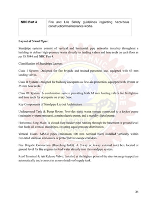
Layout of Stand Pipes:
Standpipe systems consist of vertical and horizontal pipe networks installed throughout a
building to deliver high-pressure water directly to landing valves and hose reels on each floor as
per IS 3844 and NBC Part 4.
Classification of Standpipe Layouts
Class I System: Designed for fire brigade and trained personnel use, equipped with 63 mm
landing valves.
Class II System: Designed for building occupants as first-aid protection, equipped with 19 mm or
25 mm hose reels.
Class III System: A combination system providing both 63 mm landing valves for firefighters
and hose reels for occupants on every floor.
Key Components of Standpipe Layout Architecture
Underground Tank & Pump Room: Provides static water storage connected to a jockey pump
(maintains system pressure), a main electric pump, and a standby diesel pump.
Horizontal Ring Main: A closed-loop header pipe running through the basement or ground level
that feeds all vertical standpipes, ensuring equal pressure distribution.
Vertical Risers: MS/GI pipes (minimum 100 mm nominal bore) installed vertically within
fire-rated staircase enclosures or protected fire escape corridors.
Fire Brigade Connection (Breeching Inlet): A 2-way or 4-way external inlet box located at
ground level for fire engines to feed water directly into the standpipe system.
Roof Terminal & Air Release Valve: Installed at the highest point of the riser to purge trapped air
automatically and connect to an overhead roof supply tank.
31
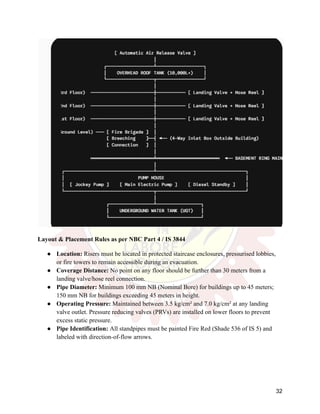
Layout & Placement Rules as per NBC Part 4 / IS 3844
●​ Location: Risers must be located in protected staircase enclosures, pressurised lobbies,
or fire towers to remain accessible during an evacuation.
●​ Coverage Distance: No point on any floor should be further than 30 meters from a
landing valve/hose reel connection.
●​ Pipe Diameter: Minimum 100 mm NB (Nominal Bore) for buildings up to 45 meters;
150 mm NB for buildings exceeding 45 meters in height.
●​ Operating Pressure: Maintained between 3.5 kg/cm² and 7.0 kg/cm² at any landing
valve outlet. Pressure reducing valves (PRVs) are installed on lower floors to prevent
excess static pressure.
●​ Pipe Identification: All standpipes must be painted Fire Red (Shade 536 of IS 5) and
labeled with direction-of-flow arrows.
32
Standpipe Layout Technical Specifications
System
Component
Minimum Pipe
Size
Recommended
Pressure
Applicable
Indian
Standard
Main Risers
(Internal)
100 mm to 150
mm MS
3.5 to 7.0 kg/cm² IS 1239 / IS
3844
External Yard
Main
150 mm Cast
Iron / MS
7.0 kg/cm² IS 13039
Landing Valve
Outlet
63 mm
Instantaneous
Minimum 3.5
kg/cm²
IS 5290
First-Aid Hose
Reel
19 mm / 25 mm
Rubber
2.0 to 3.5 kg/cm² IS 884
Fire Station:
A fire station is a operational headquarters designed to house fire tenders, firefighting personnel,
rescue equipment, and control systems for rapid response to fire and rescue emergencies.
In fire engineering, the design and functional layout of a fire station are governed by NBC Part
4 (Fire & Life Safety) and guidelines from state fire services (e.g., Delhi Fire Service, MFSC).
1. Key Functional Zones of a Fire Station
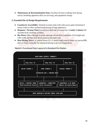
●​ Apparatus Bay (Engine Room): The core operational area where fire engines, water
tenders, foam tenders, and hydraulic platforms are parked for immediate turnout.
●​ Watch Room / Control Room: The communication center equipped with hotlines,
wireless communication, fire alarm receivers, and turnout bell controls.
●​ Personnel & Living Quarters: Includes the duty officer’s room, firefighters' barracks,
mess, recreation room, and washrooms.
33
●​ Maintenance & Decontamination Zone: Facilities for hose washing, hose drying
towers, breathing apparatus (BA) set servicing, and equipment storage.
2. Essential Site & Design Requirements
●​ Location & Accessibility: Situated on main roads with wide access gates (minimum 6
meters wide) to allow unobstructed turnout of large appliances.
●​ Response / Turnout Time: Layout must facilitate a turnout time of under 1 minute (60
seconds) from receiving an alarm.
●​ Bay Doors: Drive-through or quick-opening roll-up doors (minimum 4.5m height and
4.0m width per bay) with direct access to the main road.
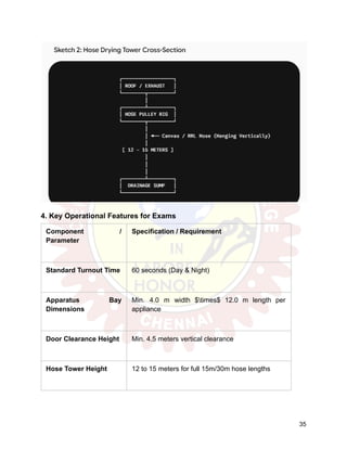
●​ Hose Drying Tower: A vertical tower (12–15 meters high) used to hang wet canvas/RRL
delivery hoses vertically for natural air drying to prevent fungal decay.
34
4. Key Operational Features for Exams
Component /
Parameter
Specification / Requirement
Standard Turnout Time 60 seconds (Day & Night)
Apparatus Bay
Dimensions
Min. 4.0 m width $times$ 12.0 m length per
appliance
Door Clearance Height Min. 4.5 meters vertical clearance
Hose Tower Height 12 to 15 meters for full 15m/30m hose lengths
35
Communication
Systems
P&T Hotline, Very High Frequency (VHF) Radio,
Automatic Turnout Bells
Fire Alarms and Sirens:
In fire engineering, fire alarms and sirens form the critical early warning and
audio-visual notification component of active fire protection systems. Governed primarily
by IS 2189 (Code of Practice for Selection, Installation, and Maintenance of Automatic
Fire Detection and Alarm System) and the National Building Code (NBC) Part 4,
these devices ensure immediate evacuation and alert emergency response teams.
1. Key Functions of Fire Alarms and Sirens
●​ Early Detection & Notification: Detects smoke/heat or manual initiation and
immediately alerts building occupants.
●​ Audio-Visual Evacuation Signal: Emits loud, distinct sound waves along with
flashing strobe lights to guide occupants, including hearing- or visually-impaired
persons.
●​ System Interfacing: Automatically triggers auxiliary safety systems (e.g.,
stopping HVAC blowers to prevent smoke spread, releasing fire doors, grounding
elevators, and starting smoke extraction fans).
2. Classification of Fire Alarm Systems
A. Conventional Fire Alarm System
●​ The building is divided into simple radial zones.
●​ Detectors in a specific zone share a common wire loop. When activated, the
panel indicates the zone number but not the exact room or detector location.
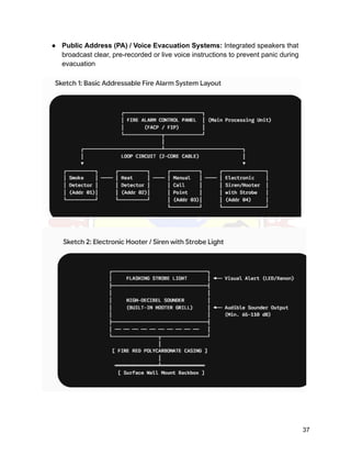
B. Addressable / Intelligent Fire Alarm System
●​ Every detector, manual call point (MCP), and sounder/siren has a unique digital
microchip address on a loop circuit.
●​ The Fire Alarm Control Panel (FACP) pinpoints the exact physical location of the
activated device on an LCD interface.
3. Notification Devices (Sirens, Hooters, & Visual Indicators)
●​ Electronic Hooters / Sirens: High-decibel sounders generating continuous or
dual-tone wailing sounds.
●​ Strobe Lights / Flashing Beacons: High-intensity Xenon or LED flashing visual
alerts mounted alongside audible sounders.
36
●​ Public Address (PA) / Voice Evacuation Systems: Integrated speakers that
broadcast clear, pre-recorded or live voice instructions to prevent panic during
evacuation
37
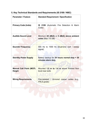
5. Key Technical Standards and Requirements (IS 2189 / NBC)
Parameter / Feature Standard Requirement / Specification
Primary Code (India) IS 2189 (Automatic Fire Detection & Alarm
Code)
Audible Sound Level Minimum 65 dB(A) or 5 dB(A) above ambient
noise (Max 110 dB)
Sounder Frequency 500 Hz to 1000 Hz (Dual-tone wail / sweep
signal)
Standby Power Supply Battery backup for 24 hours normal duty + 30
minutes alarm duty
Manual Call Point (MCP)
Height
Mounted 1.2 m to 1.4 m above finished floor
level near exits
Wiring Requirements Fire-resistant / Armored copper cables (e.g.,
FRLS grade)
38
Maintenance of Fire Trucks:
Maintenance of fire trucks (fire tenders) ensures maximum operational readiness, prevents
mechanical failure during emergency turnouts, and extends vehicle service life in compliance
with Indian Standards (IS 951, IS 6067) and the Motor Vehicles Act.
Categories of Maintenance Schedules
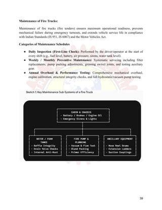
●​ Daily Inspection (First-Line Check): Performed by the driver/operator at the start of
every shift (e.g., fuel level, battery, air pressure, sirens, water tank level).
●​ Weekly / Monthly Preventive Maintenance: Systematic servicing including filter
replacements, pump packing adjustments, greasing swivel joints, and testing auxiliary
gear.
●​ Annual Overhaul & Performance Testing: Comprehensive mechanical overhaul,
engine calibration, structural integrity checks, and full hydrostatic/vacuum pump testing.
39
Maintenance Checklist by Sub-System
1. Engine & Chassis Maintenance
●​ Fuel & Oil: Maintain fuel tank above 3/4 capacity at all times. Check engine oil,
coolant levels, and transmission fluid daily.
●​ Electrical & Battery: Test 12V/24V batteries, alternator output, flashing light
bars, multi-tone sirens, and searchlights.
●​ Brakes & Tyres: Inspect air brake tank pressure (maintain above 6–8 kg/cm^2),
check tyre tread depth, and maintain inflation pressure.
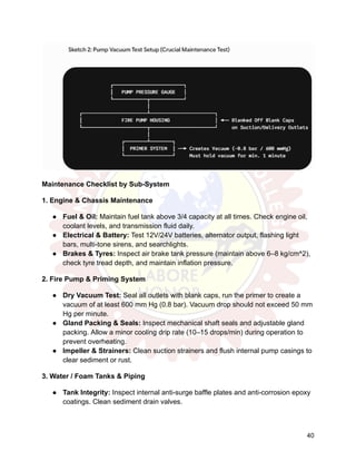
2. Fire Pump & Priming System
●​ Dry Vacuum Test: Seal all outlets with blank caps, run the primer to create a
vacuum of at least 600 mm Hg (0.8 bar). Vacuum drop should not exceed 50 mm
Hg per minute.
●​ Gland Packing & Seals: Inspect mechanical shaft seals and adjustable gland
packing. Allow a minor cooling drip rate (10–15 drops/min) during operation to
prevent overheating.
●​ Impeller & Strainers: Clean suction strainers and flush internal pump casings to
clear sediment or rust.
3. Water / Foam Tanks & Piping
●​ Tank Integrity: Inspect internal anti-surge baffle plates and anti-corrosion epoxy
coatings. Clean sediment drain valves.
40
●​ Valves & Couplings: Lubricate quick-acting ball valves, delivery landing
couplings, and suction threads with graphite grease.
Fire Truck Maintenance Log Matrix
Maintenance
Frequency
Key Inspection Items Governing Code
/ Standard
Daily (Shift
Change)
Engine start-up, water tank level,
siren/lights, brake air pressure.
Fire Service
Rules / IS 951
Weekly Dry vacuum test, hose reel
operation, PTO (Power Take-Off)
engagement.
IS 6067
Monthly Battery electrolyte levels, foam
proportioner testing, ladder locks
greasing.
OISD-STD-115 /
NBC
Annually Hydrostatic pressure test of pump
(1.5x working pressure), deep lift
flow test.
IS 1370 / Motor
Vehicles Act
41
Foam Generators:
In fire engineering, a foam generator is a specialized mechanical device designed to mix water,
foam concentrate, and air in precise proportions to produce large volumes of fire-extinguishing
foam.Foam generators are primarily used for Medium Expansion and High Expansion foam
applications, enabling rapid total flooding of enclosed, hard-to-reach areas such as basements,
cable tunnels, aircraft hangars, and ship holds.
1. Classification by Foam Expansion Ratio
Low Expansion Foam (< 20:1): Produced by foam branchpipes and monitors; used for open
flammable liquid spills (petrol tanks).
Medium Expansion Foam (20:1 to 200:1): Produced by medium expansion
branchpipes/generators; creates a thick blanket over liquid spills in bunded areas.
High Expansion Foam (200:1 to 1000:1): Produced by powered foam generators; rapidly fills
three-dimensional volumes to extinguish fires by total encapsulation, smothering, and cooling.
2. Working Principle of a Foam Generator
Solution Supply: A pre-mixed solution of water and foam concentrate (typically 3% or 6% ratio)
is delivered under pressure to the generator nozzle.
Atomization: The internal spray nozzles atomize the solution into a fine mist directed toward a
porous screen or mesh net.
Air Entrainment: Air is introduced into the chamber—either drawn naturally via a venturi effect
or forced through an internal water-turbine-driven fan.
Foam Bubble Generation: As the solution mist and high-velocity air pass simultaneously through
the mesh net, surface tension forms billions of lightweight, uniform foam bubbles.
42
43
4. Major Components of High Expansion Generators
●​ Foam Solution Inlet & Bypass Valve: Connects to 63mm instantaneous fire hose
fittings; includes a bypass valve to adjust water flow to the turbine.
●​ Water Turbine: Powered directly by the water pressure of the incoming foam solution,
driving the internal fan without requiring external electrical power.
●​ Blower Fan: Draws ambient air at high velocity to achieve high expansion ratios.
●​ Spray Manifold / Nozzles: Disperses the foam solution evenly across the entire surface
area of the mesh.
●​ Foam Screen / Net: Stainless steel or nylon mesh screen where air and liquid mist
combine to create foam bubbles.
5. Applications in Fire Engineering
●​ Basements & Underground Car Parks: Rapidly fills large subterranean spaces where
smoke visibility is zero and physical entry is hazardous.
●​ Cable Vaults & Tunnels: Smothers deep-seated electrical cable insulation fires.
●​ Ship Holds & Engine Rooms: Flood-extinguishes enclosed machinery areas.
●​ Hazardous Chemical Warehouses: Prevents toxic gas vapor release and smothers
flammable liquid pools.
6. Key Indian Standards
Parameter / Element Standard /
Guideline
Requirement / Specification
High Expansion Foam
Systems Code
IS 12835 Code of practice for fixed
high-expansion foam systems.
Foam Concentrate
Specifications
IS 4989 Synthetic, AFFF, and High
Expansion concentrate
requirements.
Foam Equipment &
Branchpipes
IS 10502 Design and performance
guidelines for foam equipment.
44
Expansion Ratios NBC Part 4 High expansion: > 200:1;
Medium expansion: 20:1 to
200:1.
Operating Pressure Standard
Field Specs
Nominal working pressure of 5.0
to 7.0 $kg/cm^2$ at the inlet.
Escape from Fire Rescue Operations:
In fire engineering, escape and fire rescue operations refer to the techniques,
structural pathways, and tactical procedures designed to safely evacuate building
occupants and perform search and rescue during a fire emergency.
As per the National Building Code (NBC) Part 4 (Fire & Life Safety) and Indian
diploma curricula, escape and rescue operations are divided into Self-Evacuation
(Means of Escape) and Fire Brigade Rescue Operations.
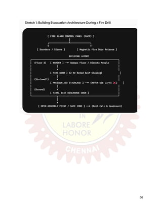
1. Components of Means of Escape (Egress Architecture)
Occupant escape relies on an uninterrupted, fire-protected path consisting of three
primary stages:
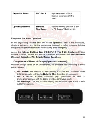
1.​ Exit Access: The corridor or aisle leading to a safe exit. Maximum travel
distance is usually restricted to 22.5 m to 30 m depending on occupancy.
2.​ Exit: A fire-rated enclosed component (e.g., pressurized fire tower or
smoke-proof staircase with fire doors) providing continuous safety.
3.​ Exit Discharge: The final door discharging directly into an open space or safe
public thoroughfare.
45
2. Special Architectural Escape Features
●​ Pressurized Staircases: Air blowers inject outside air into stairwells to create
positive pressure, keeping smoke out when fire doors open.
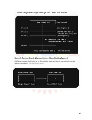
●​ Refuge Area: A protected, fire-resisting space inside high-rise buildings
designed for occupants to wait safely during phased evacuation. Mandatory at 24
meters height and every 15 meters height thereafter in buildings >24 m.
●​ Horizontal Exit: A fire-resisting wall or door partition dividing a floor into two
distinct zones, allowing occupants to escape horizontally to a safe area on the
same level.
3. Fire Brigade Rescue Operations & Equipment
When primary egress routes are compromised by heavy smoke or fire, emergency
responders deploy specialized rescue gear:
●​ Extension & Hook Ladders: Used for second/third-floor window and balcony
rescues.
●​ Aerial Hydraulic Platforms & Turntable Ladders (TTL): Truck-mounted
articulated boom platforms used to reach victims trapped on high-rise upper
floors.
●​ Inflatable Cushion / Rescue Jump Pad: Deployed at ground level directly
below windows for emergency low-height jumps when all exit routes are blocked.
●​ Continuous Escape Chutes: Heat-resistant fabric tubes allowing rapid sliding
evacuation from multi-story windows.
46
47
5. Summary Table
Parameter / Feature NBC Part 4 / Indian Standard Provision
Minimum Staircase
Width
1.25 m (Residential), 1.5 m (Educational), 2.0 m
(Assembly/Hospitals)
First Refuge Area
Requirement
Mandatory at 24 m height, then every 15 m
above
Max Travel Distance 22.5 m (Un-sprinklered), 30 m (Sprinklered
business/industrial)
Fire Door Rating Minimum 2 Hours Fire Resistance Rating (FRR)
with panic bar release
Smoke Pressurization
Level
50 Pa differential pressure in stairwells against
adjacent spaces
Fire Drills:
In fire engineering, a fire drill is a simulated, supervised emergency practice designed
to rehearse building evacuation procedures, test life safety systems, and train
occupants and fire wardens on systematic action during a fire.
In India, fire drills are governed by the National Building Code (NBC) Part 4 (Fire &
Life Safety) and the State Fire Services Act. As per NBC 2016 Annex D, fire drills
must be conducted at least once every 3 months for the first two years after building
commissioning, and at least once every 6 months thereafter.
1. Key Objectives of a Fire Drill
●​ Inculcate Muscle Memory: Prevents panic by training occupants to
automatically use protected staircases instead of lifts.
48
●​ Test Emergency Infrastructure: Verifies the operation of Manual Call Points
(MCPs), sounders, strobes, public address (PA) systems, and automatic door
releases.
●​ Verify Warden Readiness: Evaluates floor wardens on floor sweeping,
accounting for occupants, and assisting non-ambulant persons to designated
refuge areas.
●​ Identify Bottlenecks: Pinpoints delayed response times, blocked escape routes,
locked emergency doors, or audio dead zones.
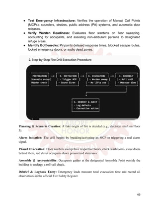
Planning & Scenario Creation: A fake origin of fire is decided (e.g., electrical shaft on Floor
3).
Alarm Initiation: The drill begins by breaking/activating an MCP or triggering a real alarm
signal.
Phased Evacuation: Floor wardens sweep their respective floors, check washrooms, close doors
behind them, and direct occupants down pressurized staircases.
Assembly & Accountability: Occupants gather at the designated Assembly Point outside the
building to undergo a roll-call check.
Debrief & Logbook Entry: Emergency leads measure total evacuation time and record all
observations in the official Fire Safety Register.
49
50
4. Roles and Responsibilities During Drills
Role Key Duties During Drill
Chief Fire Marshal /
Safety Officer
Initiates drill, monitors overall timing, liaises with
municipal fire service, leads debrief.
Floor Fire Wardens Wears high-vis vests, clears floor, ensures no one
uses elevators, directs movement to stairs.
Searchers / Sweepers Checks toilets, server rooms, and remote spaces to
confirm complete clearance.
Assembly Point
Coordinator
Maintains attendance registers, performs roll calls,
reports missing persons to Chief Marshal.
51
Fire Prevention Notice:
In fire engineering, a Fire Protection Notice (also known as a Fire Action Notice) is a
standardized, highly visible instructional sign posted along escape routes and key building areas.
It provides clear, step-by-step instructions on what actions occupants must take upon discovering
a fire or hearing a fire alarm.
As per the National Building Code (NBC) Part 4 and IS 9457 / IS 12349 (Safety Signs and
Symbols), these notices serve as vital passive emergency communication tools to prevent panic
and ensure orderly evacuation.
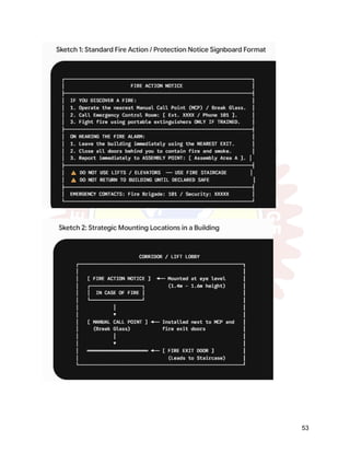
1. Key Essential Contents of a Fire Protection Notice
A standard Fire Action Notice is divided into four critical functional sections:
●​ Action on Discovering a Fire: Instructions on raising the alarm immediately via the
nearest Manual Call Point (MCP) and notifying the fire control room.
●​ Action on Hearing the Fire Alarm: Immediate evacuation steps, directing occupants to
leave the area using designated emergency exit staircases.
●​ Prohibition Warnings (Do's and Don'ts): Critical safety rules, such as "DO NOT USE
LIFTS/ELEVATORS" and "DO NOT RUN OR OVERTAKE ON STAIRS."
●​ Assembly Point & Contacts: Specific location of the external Assembly Point and
emergency telephone numbers (e.g., Fire Brigade: 101/112, Plant Emergency Control
Room).
52
53
3. Color Coding Standards for Safety Signs (IS 9457)
To convey emergency instructions rapidly, Fire Protection Notices utilize standardized
safety color schemes as mandated by the Bureau of Indian Standards (BIS):
Color
Scheme
Meaning /
Classification
Application Example in Notice
Red Prohibitive Action / Fire
Equipment
"DO NOT USE LIFTS", Fire
Hose/Extinguisher locations
Blue Mandatory Action "USE FIRE EXIT STAIRCASE",
"CLOSE DOORS"
Yellow /
Amber
Caution / Risk Warning "WARNING: FLAMMABLE
MATERIAL", High voltage risk
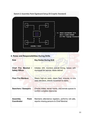
Green Safe Condition / Egress "ASSEMBLY POINT", Emergency
exit direction signs
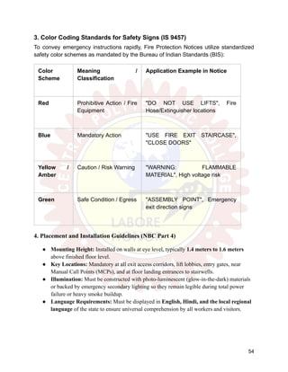
4. Placement and Installation Guidelines (NBC Part 4)
●​ Mounting Height: Installed on walls at eye level, typically 1.4 meters to 1.6 meters
above finished floor level.
●​ Key Locations: Mandatory at all exit access corridors, lift lobbies, entry gates, near
Manual Call Points (MCPs), and at floor landing entrances to stairwells.
●​ Illumination: Must be constructed with photo-luminescent (glow-in-the-dark) materials
or backed by emergency secondary lighting so they remain legible during total power
failure or heavy smoke buildup.
●​ Language Requirements: Must be displayed in English, Hindi, and the local regional
language of the state to ensure universal comprehension by all workers and visitors.
54
First Aid for Burns:
In fire engineering, first aid for burns involves immediate life safety protocols, surface
cooling, and stabilizing victims before advanced medical help arrives. In India, burn
management procedures follow guidelines from the National Building Code (NBC)
Part 4, the Factories Act, 1948, and the Indian Red Cross Society.
1. Classification of Burns by Depth
●​ First-Degree (Superficial): Affects only the outer skin layer (epidermis). Causes
redness, mild swelling, and pain (e.g., minor steam burns).
●​ Second-Degree (Partial Thickness): Damage extends into the inner layer
(dermis). Characterized by blisters, severe pain, and raw skin.
●​ Third-Degree (Full Thickness): Complete destruction of skin, underlying
tissues, nerves, and blood vessels. Skin appears charred, white, or leathery, and
may feel painless due to destroyed nerve endings.
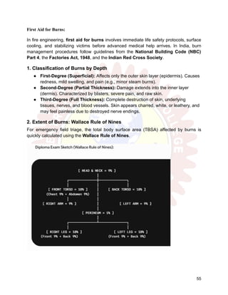
2. Extent of Burns: Wallace Rule of Nines
For emergency field triage, the total body surface area (TBSA) affected by burns is
quickly calculated using the Wallace Rule of Nines.
55
3. Step-by-Step First Aid Protocol (3Cs Method)
A. COOL (Immediate Thermal Control)
●​ Cool the burn area with clean, running tap water for at least 10 to 20 minutes.
●​ Do NOT use ice, ice water, butter, grease, or ink, as they cause tissue necrosis and
introduce severe bacterial infection.
B. COVER (Protection Against Infection)
●​ Cover the burn loosely with a sterile, non-adherent burn dressing, clean lint-free cloth, or
sterile plastic wrap.
●​ Do NOT pop or puncture blisters, as they act as a natural sterile barrier.
C. CALL (Emergency Medical Evacuation)
●​ Arrange immediate transport to a burn unit if the burn covers more than 10% TBSA,
involves chemical/electrical sources, or affects critical areas (face, hands, joints, or
airways).
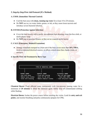
4. Specific First Aid Treatment by Burn Type
Chemical Burns: Flush affected areas continuously with low-pressure running water for a
minimum of 20 minutes to dilute the chemical agent. Safely strip off contaminated clothing
while flushing.
Electrical Burns: Isolate the power source before touching the victim. Look for entry and exit
points, and monitor breathing and pulse continuously (prepare for CPR).
56
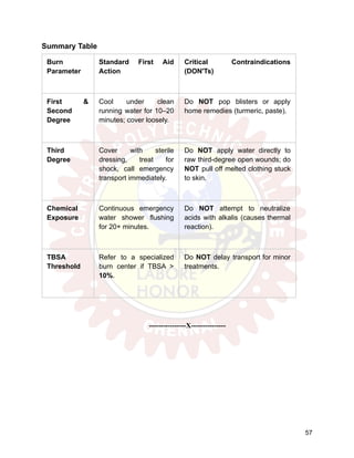
Summary Table
Burn
Parameter
Standard First Aid
Action
Critical Contraindications
(DON'Ts)
First &
Second
Degree
Cool under clean
running water for 10–20
minutes; cover loosely.
Do NOT pop blisters or apply
home remedies (turmeric, paste).
Third
Degree
Cover with sterile
dressing, treat for
shock, call emergency
transport immediately.
Do NOT apply water directly to
raw third-degree open wounds; do
NOT pull off melted clothing stuck
to skin.
Chemical
Exposure
Continuous emergency
water shower flushing
for 20+ minutes.
Do NOT attempt to neutralize
acids with alkalis (causes thermal
reaction).
TBSA
Threshold
Refer to a specialized
burn center if TBSA >
10%.
Do NOT delay transport for minor
treatments.
----------------X---------------
57
58